2006 INFINITI M35 belt
[x] Cancel search: beltPage 4786 of 5621
PERIODIC MAINTENANCE
MA-9
C
D
E
F
G
H
I
J
K
MA
B
MA
Revision: 2006 January2006 M35/M45
NOTE:
(1) After 60,000 miles (96,000 km) or 48 months, inspect every 15,000 miles (24,000 km) or 12 months. Replace the drive belts if found
damaged or if the auto belt tensioner reading (only for VK45DE engine) reaches the maximum limit.
(2) If operating mainly in dusty conditions, more frequent maintenance may be required.
(3) Maintenance-free item. For service procedures, refer to FL section.
(4) After 60,000 miles (96,000 km) or 48 months, replace every 30,000 miles (48,000 km) or 24 months.
(5) If valve noise increases, inspect valve clearance.
* Maintenance items and intervals with “*” are recommended by INFINITI for reliable vehicle operation. The owner need not perform
such maintenance in order to maintain the emission warranty or manufacturer recall liability. Other maintenance items and intervals are
required.
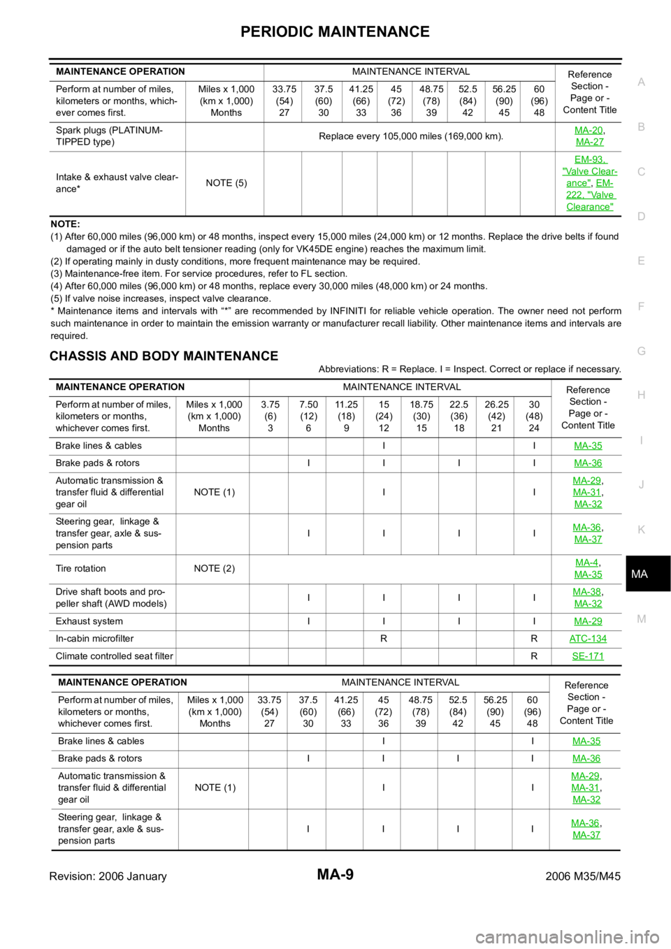
CHASSIS AND BODY MAINTENANCE
Abbreviations: R = Replace. I = Inspect. Correct or replace if necessary. Spark plugs (PLATINUM-
TIPPED type)Replace every 105,000 miles (169,000 km).MA-20
,
MA-27
Intake & exhaust valve clear-
ance*NOTE (5)EM-93, "Valve Clear-
ance", EM-
222, "Va l v e
Clearance"
MAINTENANCE OPERATIONMAINTENANCE INTERVAL
Reference
Section -
Page or -
Content Title Perform at number of miles,
kilometers or months, which-
ever comes first.Miles x 1,000
(km x 1,000)
Months33.75
(54)
2737.5
(60)
3041.25
(66)
3345
(72)
3648.75
(78)
3952.5
(84)
4256.25
(90)
4560
(96)
48
MAINTENANCE OPERATIONMAINTENANCE INTERVAL
Reference
Section -
Page or -
Content Title Perform at number of miles,
kilometers or months,
whichever comes first.Miles x 1,000
(km x 1,000)
Months3.75
(6)
37.50
(12)
611 . 2 5
(18)
915
(24)
1218.75
(30)
1522.5
(36)
1826.25
(42)
2130
(48)
24
Brake lines & cables I IMA-35
Brake pads & rotors I I I IMA-36
Automatic transmission &
transfer fluid & differential
gear oilNOTE (1) I IMA-29,
MA-31
,
MA-32
Steering gear, linkage &
transfer gear, axle & sus-
pension partsIIIIMA-36,
MA-37
Tire rotation NOTE (2)MA-4,
MA-35
Drive shaft boots and pro-
peller shaft (AWD models) IIIIMA-38,
MA-32
Exhaust system I I I IMA-29
In-cabin microfilter R RAT C - 1 3 4
Climate controlled seat filterRSE-171
MAINTENANCE OPERATIONMAINTENANCE INTERVAL
Reference
Section -
Page or -
Content Title Perform at number of miles,
kilometers or months,
whichever comes first.Miles x 1,000
(km x 1,000)
Months33.75
(54)
2737.5
(60)
3041.25
(66)
3345
(72)
3648.75
(78)
3952.5
(84)
4256.25
(90)
4560
(96)
48
Brake lines & cables I IMA-35
Brake pads & rotors I I I IMA-36
Automatic transmission &
transfer fluid & differential
gear oilNOTE (1) I IMA-29,
MA-31
,
MA-32
Steering gear, linkage &
transfer gear, axle & sus-
pension partsI IIIMA-36,
MA-37
Page 4787 of 5621
MA-10
PERIODIC MAINTENANCE
Revision: 2006 January2006 M35/M45
NOTE:
(1) If towing a trailer, using a camper or a car-top carrier, or driving on rough or muddy roads, change (not just inspect) fluid (A/T, trans-
fer)/oil at every 30,000 miles (48,000 km) or 24 months. Using automatic transmission fluid other than Genuine NISSAN Matic J
ATF will cause deterioration in driveability and automatic transmission durability, and may damage the automatic transmis-
sion, which is not covered by the INFINITI new vehicle limited warranty.
(2) Refer to “Tire rotation” under the “GENERAL MAINTENANCE” heading earlier in this section.
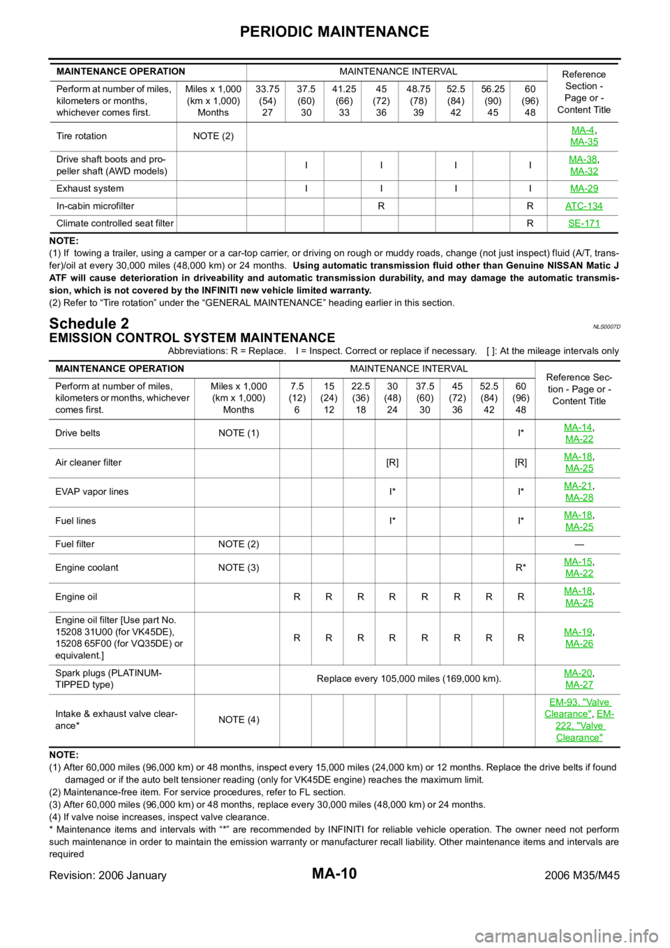
Schedule 2NLS0007D
EMISSION CONTROL SYSTEM MAINTENANCE
Abbreviations: R = Replace. I = Inspect. Correct or replace if necessary. [ ]: At the mileage intervals only
NOTE:
(1) After 60,000 miles (96,000 km) or 48 months, inspect every 15,000 miles (24,000 km) or 12 months. Replace the drive belts if found
damaged or if the auto belt tensioner reading (only for VK45DE engine) reaches the maximum limit.
(2) Maintenance-free item. For service procedures, refer to FL section.
(3) After 60,000 miles (96,000 km) or 48 months, replace every 30,000 miles (48,000 km) or 24 months.
(4) If valve noise increases, inspect valve clearance.
* Maintenance items and intervals with “*” are recommended by INFINITI for reliable vehicle operation. The owner need not perform
such maintenance in order to maintain the emission warranty or manufacturer recall liability. Other maintenance items and intervals are
required Tire rotation NOTE (2)MA-4
,
MA-35
Drive shaft boots and pro-
peller shaft (AWD models)I IIIMA-38,
MA-32
Exhaust system I I I IMA-29
In-cabin microfilter R RATC-134
Climate controlled seat filterRSE-171
MAINTENANCE OPERATIONMAINTENANCE INTERVAL
Reference
Section -
Page or -
Content Title Perform at number of miles,
kilometers or months,
whichever comes first.Miles x 1,000
(km x 1,000)
Months33.75
(54)
2737.5
(60)
3041.25
(66)
3345
(72)
3648.75
(78)
3952.5
(84)
4256.25
(90)
4560
(96)
48
MAINTENANCE OPERATIONMAINTENANCE INTERVAL
Reference Sec-
tion - Page or -
Content Title Perform at number of miles,
kilometers or months, whichever
comes first.Miles x 1,000
(km x 1,000)
Months7.5
(12)
615
(24)
1222.5
(36)
1830
(48)
2437.5
(60)
3045
(72)
3652.5
(84)
4260
(96)
48
Drive belts NOTE (1) I*MA-14
,
MA-22
Air cleaner filter [R] [R]MA-18,
MA-25
EVAP vapor lines I* I*MA-21,
MA-28
Fuel lines I* I*MA-18,
MA-25
Fuel filter NOTE (2)—
Engine coolant NOTE (3) R*MA-15
,
MA-22
Engine oil RRRRRRRRMA-18,
MA-25
Engine oil filter [Use part No.
15208 31U00 (for VK45DE),
15208 65F00 (for VQ35DE) or
equivalent.]RRRR R RRRMA-19
,
MA-26
Spark plugs (PLATINUM-
TIPPED type)Replace every 105,000 miles (169,000 km).MA-20,
MA-27
Intake & exhaust valve clear-
ance*NOTE (4)EM-93, "
Va l v e
Clearance", EM-
222, "Va l v e
Clearance"
Page 4791 of 5621
MA-14
ENGINE MAINTENANCE (VQ35DE ENGINE)
Revision: 2006 January2006 M35/M45
ENGINE MAINTENANCE (VQ35DE ENGINE)PFP:10001
Checking Drive BeltsNLS0007H
WAR NING :
Be sure to perform when engine is stopped.
1. Inspect belts for cracks, fraying, wear and oil. If necessary, replace.
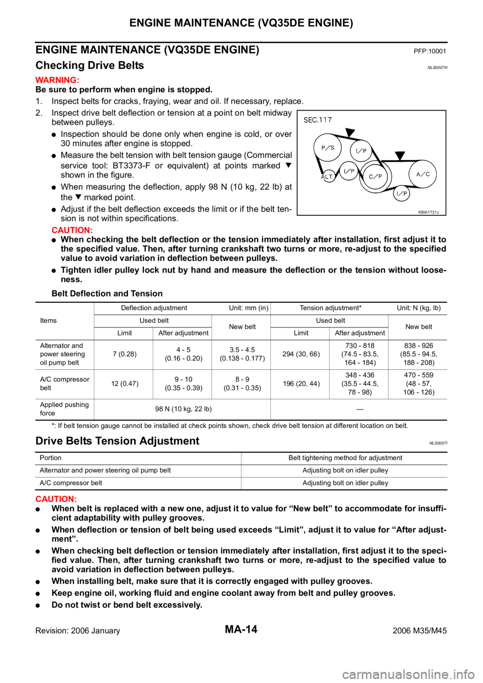
2. Inspect drive belt deflection or tension at a point on belt midway
between pulleys.
Inspection should be done only when engine is cold, or over
30 minutes after engine is stopped.
Measure the belt tension with belt tension gauge (Commercial
service tool: BT3373-F or equivalent) at points marked
shown in the figure.
When measuring the deflection, apply 98 N (10 kg, 22 lb) at
the marked point.
Adjust if the belt deflection exceeds the limit or if the belt ten-
sion is not within specifications.
CAUTION:
When checking the belt deflection or the tension immediately after installation, first adjust it to
the specified value. Then, after turning crankshaft two turns or more, re-adjust to the specified
value to avoid variation in deflection between pulleys.
Tighten idler pulley lock nut by hand and measure the deflection or the tension without loose-
ness.
Belt Deflection and Tension
*: If belt tension gauge cannot be installed at check points shown, check drive belt tension at different location on belt.
Drive Belts Tension AdjustmentNLS0007I
CAUTION:
When belt is replaced with a new one, adjust it to value for “New belt” to accommodate for insuffi-
cient adaptability with pulley grooves.
When deflection or tension of belt being used exceeds “Limit”, adjust it to value for “After adjust-
ment”.
When checking belt deflection or tension immediately after installation, first adjust it to the speci-
fied value. Then, after turning crankshaft two turns or more, re-adjust to the specified value to
avoid variation in deflection between pulleys.
When installing belt, make sure that it is correctly engaged with pulley grooves.
Keep engine oil, working fluid and engine coolant away from belt and pulley grooves.
Do not twist or bend belt excessively.
KBIA1731J
ItemsDeflection adjustment Unit: mm (in) Tension adjustment* Unit: N (kg, lb)
Used belt
New beltUsed belt
New belt
Limit After adjustment Limit After adjustment
Alternator and
power steering
oil pump belt7 (0.28)4 - 5
(0.16 - 0.20)3.5 - 4.5
(0.138 - 0.177)294 (30, 66)730 - 818
(74.5 - 83.5,
164 - 184)838 - 926
(85.5 - 94.5,
188 - 208)
A/C compressor
belt12 (0.47)9 - 10
(0.35 - 0.39)8 - 9
(0.31 - 0.35)196 (20, 44)348 - 436
(35.5 - 44.5,
78 - 98)470 - 559
(48 - 57,
106 - 126)
Applied pushing
force98 N (10 kg, 22 lb) —
PortionBelt tightening method for adjustment
Alternator and power steering oil pump belt Adjusting bolt on idler pulley
A/C compressor belt Adjusting bolt on idler pulley
Page 4792 of 5621
ENGINE MAINTENANCE (VQ35DE ENGINE)
MA-15
C
D
E
F
G
H
I
J
K
MA
B
MA
Revision: 2006 January2006 M35/M45
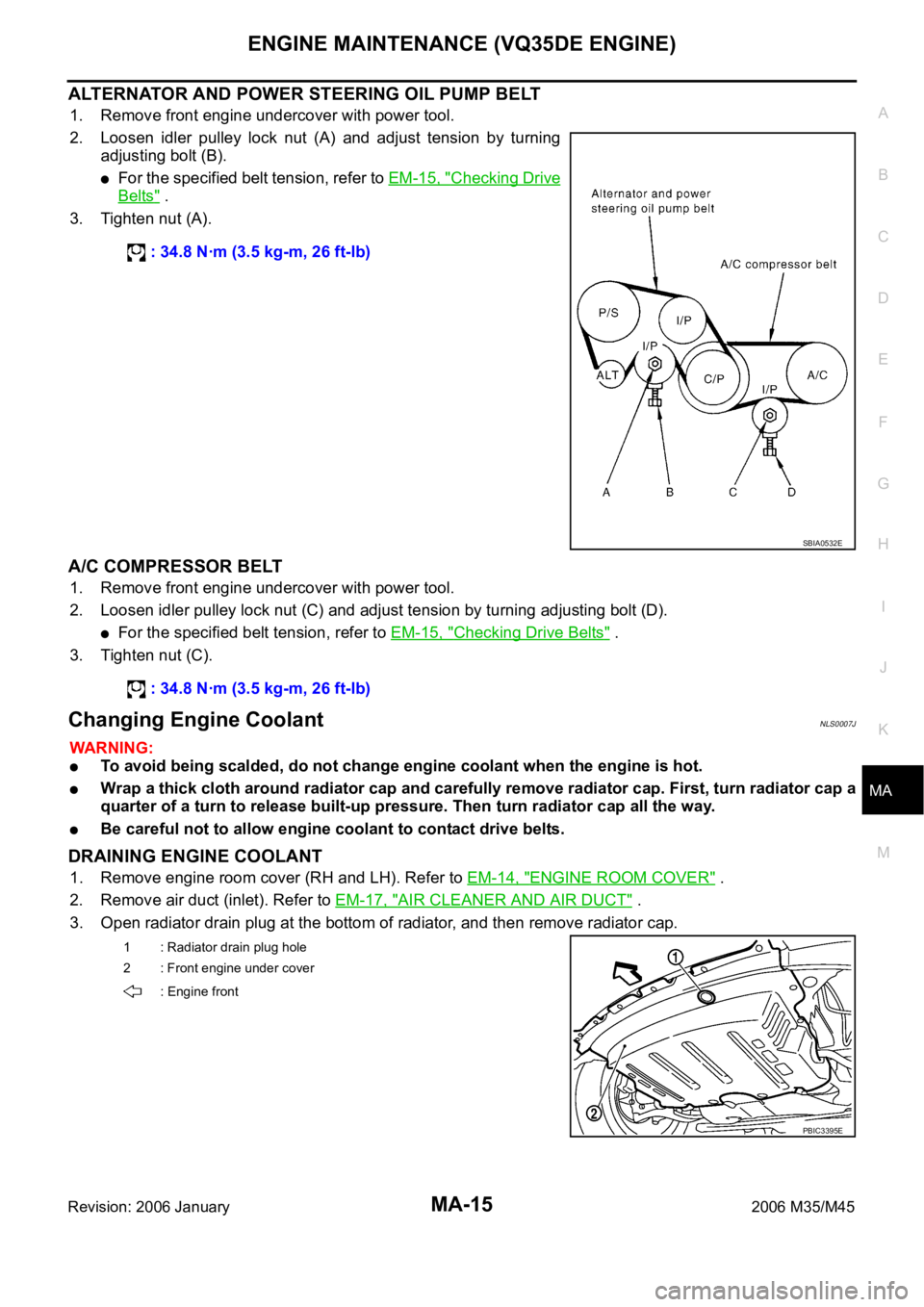
ALTERNATOR AND POWER STEERING OIL PUMP BELT
1. Remove front engine undercover with power tool.
2. Loosen idler pulley lock nut (A) and adjust tension by turning
adjusting bolt (B).
For the specified belt tension, refer to EM-15, "Checking Drive
Belts" .
3. Tighten nut (A).
A/C COMPRESSOR BELT
1. Remove front engine undercover with power tool.
2. Loosen idler pulley lock nut (C) and adjust tension by turning adjusting bolt (D).
For the specified belt tension, refer to EM-15, "Checking Drive Belts" .
3. Tighten nut (C).
Changing Engine CoolantNLS0007J
WAR NING :
To avoid being scalded, do not change engine coolant when the engine is hot.
Wrap a thick cloth around radiator cap and carefully remove radiator cap. First, turn radiator cap a
quarter of a turn to release built-up pressure. Then turn radiator cap all the way.
Be careful not to allow engine coolant to contact drive belts.
DRAINING ENGINE COOLANT
1. Remove engine room cover (RH and LH). Refer to EM-14, "ENGINE ROOM COVER" .
2. Remove air duct (inlet). Refer to EM-17, "
AIR CLEANER AND AIR DUCT" .
3. Open radiator drain plug at the bottom of radiator, and then remove radiator cap. : 34.8 Nꞏm (3.5 kg-m, 26 ft-lb)
SBIA0532E
: 34.8 Nꞏm (3.5 kg-m, 26 ft-lb)
1 : Radiator drain plug hole
2 : Front engine under cover
: Engine front
PBIC3395E
Page 4796 of 5621
ENGINE MAINTENANCE (VQ35DE ENGINE)
MA-19
C
D
E
F
G
H
I
J
K
MA
B
MA
Revision: 2006 January2006 M35/M45
CAUTION:
When filling engine oil, do not pull out oil level gauge.
The refill capacity depends on the engine oil temperature and drain time. Use these specifica-
tions for reference only.
Always use oil level gauge to determine the proper amount of engine oil in engine.
8. Warm up the engine and check area around drain plug and oil filter for engine oil leakage.
9. Stop the engine and wait for 10 minutes.
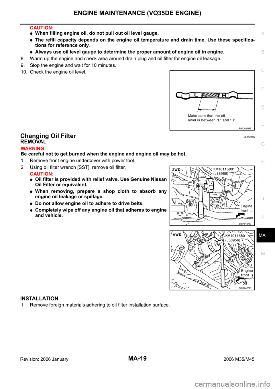
10. Check the engine oil level.
Changing Oil FilterNLS0007N
REMOVAL
WAR NING :
Be careful not to get burned when the engine and engine oil may be hot.
1. Remove front engine undercover with power tool.
2. Using oil filter wrench [SST], remove oil filter.
CAUTION:
Oil filter is provided with relief valve. Use Genuine Nissan
Oil Filter or equivalent.
When removing, prepare a shop cloth to absorb any
engine oil leakage or spillage.
Do not allow engine oil to adhere to drive belts.
Completely wipe off any engine oil that adheres to engine
and vehicle.
INSTALLATION
1. Remove foreign materials adhering to oil filter installation surface.
PBIC0249E
SBIA0454E
SBIA0455E
Page 4799 of 5621
MA-22
ENGINE MAINTENANCE (VK45DE ENGINE)
Revision: 2006 January2006 M35/M45
ENGINE MAINTENANCE (VK45DE ENGINE)PFP:10001
Checking Drive BeltsNLS0007Q
WAR NING :
Be sure to perform when the engine is stopped.
Remove air duct (inlet) when inspecting drive belt for alternator, water pump and A/C compressor.
Remove front engine undercover with power tool when inspecting power steering oil pump belt.
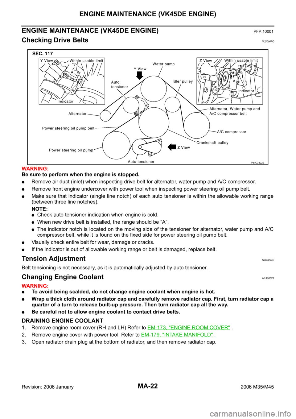
Make sure that indicator (single line notch) of each auto tensioner is within the allowable working range
(between three line notches).
NOTE:
Check auto tensioner indication when engine is cold.
When new drive belt is installed, the range should be “A”.
The indicator notch is located on the moving side of the tensioner for alternator, water pump and A/C
compressor belt, while it is found on the fixed side for power steering oil pump belt.
Visually check entire belt for wear, damage or cracks.
If the indicator is out of allowable working range or belt is damaged, replace belt.
Te n s i o n A d j u s t m e n tNLS0007R
Belt tensioning is not necessary, as it is automatically adjusted by auto tensioner.
Changing Engine CoolantNLS0007S
WAR NING :
To avoid being scalded, do not change engine coolant when engine is hot.
Wrap a thick cloth around radiator cap and carefully remove radiator cap. First, turn radiator cap a
quarter of a turn to release built-up pressure. Then turn radiator cap all the way.
Be careful not to allow engine coolant to contact drive belts.
DRAINING ENGINE COOLANT
1. Remove engine room cover (RH and LH) Refer to EM-173, "ENGINE ROOM COVER" .
2. Remove engine cover with power tool. Refer to EM-179, "
INTAKE MANIFOLD" .
3. Open radiator drain plug at the bottom of radiator, and then remove radiator cap.
PBIC3822E
Page 4803 of 5621

MA-26
ENGINE MAINTENANCE (VK45DE ENGINE)
Revision: 2006 January2006 M35/M45
7. Refill with new engine oil.
Engine oil specification and viscosity:
Refer to MA-12, "
RECOMMENDED FLUIDS AND LUBRICANTS" .
Engine oil capacity (Approximate):
Unit: (US qt, Imp qt)
CAUTION:
The refill capacity depends on the engine oil temperature and drain time. Use these specifica-
tions for reference only.
Always use oil level gauge to determine the proper amount of engine oil in the engine.
8. Warm up engine and check area around drain plug and oil filter for oil leakage.
9. Stop engine and wait for 15 minutes.
10. Check the engine oil level.
Changing Oil FilterNLS0007W
REMOVAL
WAR NING :
Be careful not to get burned when the engine and engine oil may be hot.
1. Remove front engine undercover with power tool.
2. Using the oil filter wrench (SST), remove the oil filter.
CAUTION:
Oil filter is provided with relief valve. Use Genuine Nissan
Oil Filter or equivalent.
When removing, prepare a shop cloth to absorb any
engine oil leakage or spillage.
Do not allow engine oil to adhere to drive belts.
Completely wipe off any engine oil that adhere to engine
and vehicle.
INSTALLATION
1. Remove foreign materials adhering to oil filter installation surface.
2. Apply new engine oil to the oil seal circumference of the new oil
filter.
Drain and refillWith oil filter change 5.5 (5-3/4, 4-7/8)
without oil filter change 4.9 (5-1/8, 4-1/4)
Dry engine (engine overhaul) 6.7 (7-1/8, 5-7/8)
PBIC0801E
PBIC1525E
SMA010
Page 4816 of 5621
CHASSIS AND BODY MAINTENANCE
MA-39
C
D
E
F
G
H
I
J
K
MA
B
MA
Revision: 2006 January2006 M35/M45
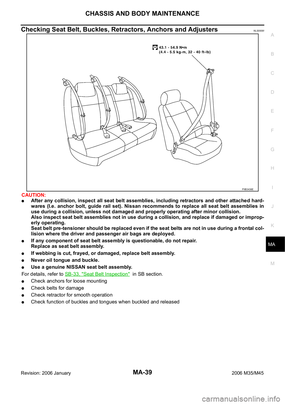
Checking Seat Belt, Buckles, Retractors, Anchors and AdjustersNLS0008I
CAUTION:
After any collision, inspect all seat belt assemblies, including retractors and other attached hard-
wares (I.e. anchor bolt, guide rail set). Nissan recommends to replace all seat belt assemblies in
use during a collision, unless not damaged and properly operating after minor collision.
Also inspect seat belt assemblies not in use during a collision, and replace if damaged or improp-
erly operating.
Seat belt pre-tensioner should be replaced even if the seat belts are not in use during a frontal col-
lision where the driver and passenger air bags are deployed.
If any component of seat belt assembly is questionable, do not repair.
Replace as seat belt assembly.
If webbing is cut, frayed, or damaged, replace belt assembly.
Never oil tongue and buckle.
Use a genuine NISSAN seat belt assembly.
For details, refer to SB-33, "
Seat Belt Inspection" in SB section.
Check anchors for loose mounting
Check belts for damage
Check retractor for smooth operation
Check function of buckles and tongues when buckled and released
PIIB3436E