2006 INFINITI M35 check oil
[x] Cancel search: check oilPage 3456 of 5621
![INFINITI M35 2006 Factory Service Manual COIL SPRING AND SHOCK ABSORBER
FSU-29
[AWD]
C
D
F
G
H
I
J
K
L
MA
B
FSU
Revision: 2006 January2006 M35/M45
2. Using a spring compressor (commercial service tool), compress
coil spring between rubber se INFINITI M35 2006 Factory Service Manual COIL SPRING AND SHOCK ABSORBER
FSU-29
[AWD]
C
D
F
G
H
I
J
K
L
MA
B
FSU
Revision: 2006 January2006 M35/M45
2. Using a spring compressor (commercial service tool), compress
coil spring between rubber se](/manual-img/42/57023/w960_57023-3455.png)
COIL SPRING AND SHOCK ABSORBER
FSU-29
[AWD]
C
D
F
G
H
I
J
K
L
MA
B
FSU
Revision: 2006 January2006 M35/M45
2. Using a spring compressor (commercial service tool), compress
coil spring between rubber seat and spring lower seat (on shock
absorber) until coil spring with a spring compressor is free.
CAUTION:
Be sure a spring compressor is securely attached coil
spring. Compress coil spring
3. Make sure coil spring with a spring compressor between rubber
seat and spring lower seat (shock absorber) is free and then
remove piston rod lock nut while securing the piston rod tip so
that piston rod does not turn.
4. Remove shock absorber mounting bracket, rubber seat, bound
bumper from shock absorber.
5. Remove coil spring with a spring compressor, and then gradually release a spring compressor.
CAUTION:
Loosen while making sure coil spring attachment position does not move.
6. Remove the strut attachment from shock absorber.
INSPECTION AFTER DISASSEMBLY
Shock Absorber Inspection
Check the following:
Shock absorber for deformation, cracks or damage, and replace it if a malfunction is detected.
Piston rod for damage, uneven wear or distortion, and replace it if a malfunction is detected.
For oil leakage, and replace it if a malfunction is detected.
Shock Absorber Mounting Bracket and Rubber Parts Inspection
Check shock absorber mounting bracket for cracks and rubber parts for wear. Replace it if a malfunction is
detected
Coil Spring Inspection
Check coil spring for cracks, wear or damage, and replace it if a malfunction is detected.
ASSEMBLY
CAUTION:
Do not damage shock absorber piston rod when installing components to shock absorber.
1. Install strut attachment [SST] to shock absorber and secure it in
a vise.
CAUTION:
When installing the strut attachment to shock absorber,
wrap a shop cloth around strut to protect it from damage.
2. Compress coil spring using a spring compressor (commercial
service tool), and install it onto shock absorber.
SEIA0297E
SEIA0296E
SEIA0297E
Page 3460 of 5621
![INFINITI M35 2006 Factory Service Manual UPPER LINK
FSU-33
[AWD]
C
D
F
G
H
I
J
K
L
MA
B
FSU
Revision: 2006 January2006 M35/M45
UPPER LINKPFP:54524
Removal and InstallationNES000IX
REMOVAL
1. Remove tires from vehicle with a power tool.
2. Re INFINITI M35 2006 Factory Service Manual UPPER LINK
FSU-33
[AWD]
C
D
F
G
H
I
J
K
L
MA
B
FSU
Revision: 2006 January2006 M35/M45
UPPER LINKPFP:54524
Removal and InstallationNES000IX
REMOVAL
1. Remove tires from vehicle with a power tool.
2. Re](/manual-img/42/57023/w960_57023-3459.png)
UPPER LINK
FSU-33
[AWD]
C
D
F
G
H
I
J
K
L
MA
B
FSU
Revision: 2006 January2006 M35/M45
UPPER LINKPFP:54524
Removal and InstallationNES000IX
REMOVAL
1. Remove tires from vehicle with a power tool.
2. Remove shock absorber. Refer to FSU-28, "
COIL SPRING AND SHOCK ABSORBER" .
3. Remove mounting nut and bolt with a power tool, and then remove upper link from steering knuckle.
4. Remove mounting nuts and bolts, and then remove upper link and stopper rubber from vehicle.
INSPECTION AFTER REMOVAL
Visual Inspection
Check the following:
Upper link and bushing for deformation, cracks or damage. Replace it if a malfunction is detected.
Ball joint boot for cracks or other damage, and also for grease leakage. Replace it if a malfunction is
detected.
Ball Joint Inspection
Manually move ball stud to confirm it moves smoothly with no binding.
Swing Torque Inspection
NOTE:
Before measurement, move ball stud at least ten times by hand to check for smooth movement.
Hook a spring balance at cutout on ball stud. Confirm spring bal-
ance measurement value is within specifications when ball stud
begins moving.
If it is outside the specified range, replace upper link assembly.
Rotating Torque Inspection
Attach mounting nut to ball stud. Make sure that rotating torque
is within specifications with a preload gauge [SST].
If it is outside the specified range, replace upper link assembly.
Axial End Play Inspection
Move tip of ball stud in axial direction to check for looseness.
If it is outside the specified range, replace upper link assembly.
INSTALLATION
Installation is the reverse order of removal. For tightening torque, refer to FSU-25, "Components" .
Perform final tightening of bolts and nuts at the vehicle installation position (rubber bushing) under
unladen conditions with tires on level ground. Check wheel alignment. Refer to FSU-23, "
Wheel Align-
ment Inspection" . Swing torque
: 0 - 2.0 Nꞏm (0 - 0.2 kg-m, 0 - 17 in-lb)
Spring balance measurement
: 0 - 61.5 N (0 - 6.2 kg, 0 - 13.6 lb)
SEIA0523E
Rotating torque
: 0 - 2.0 Nꞏm (0 - 0.2 kg-m, 0 - 17 in-lb)
SDIA1150E
Axial end play : 0 mm (0 in)
Page 3464 of 5621
GI-1
GENERAL INFORMATION
A GENERAL INFORMATION
CONTENTS
C
D
E
F
G
H
I
J
K
L
MB
GI
SECTION GI
Revision: 2006 January2006 M35/M45
GENERAL INFORMATION
PRECAUTIONS .......................................................... 3
Description ............................................................... 3
Precautions for Supplemental Restraint System
(SRS) “AIR BAG” and “SEAT BELT PRE-TEN-
SIONER” .................................................................. 3
Precautions for NVIS/IVIS (NISSAN/INFINITI
VEHICLE IMMOBILIZER SYSTEM - NATS) (If
Equipped) ................................................................. 3
Precautions Necessary for Steering Wheel Rotation
After Battery Disconnect .......................................... 4
OPERATION PROCEDURE ................................. 4
Precautions for Procedures without Cowl Top Cover ..... 4
General Precautions ................................................ 4
Precautions for Three Way Catalyst ......................... 6
Precautions for Fuel (Unleaded Premium Gasoline
Recommended) ...................................................
..... 6
Precautions for Fuel (Unleaded Premium Gasoline
Required) ................................................................. 6
Precautions for Multiport Fuel Injection System or
Engine Control System ............................................ 7
Precautions for Hoses .............................................. 7
HOSE REMOVAL AND INSTALLATION ............... 7
HOSE CLAMPING ................................................ 7
Precautions for Engine Oils ...................................... 8
HEALTH PROTECTION PRECAUTIONS ............. 8
Precautions for Air Conditioning ............................... 8
HOW TO USE THIS MANUAL ................................... 9
Description ............................................................... 9
Terms ....................................................................... 9
Units ......................................................................... 9
Contents ................................................................... 9
Relation between Illustrations and Descriptions .... 10
Components ............................................................ 11
SYMBOLS ........................................................
.... 11
How to Follow Trouble Diagnoses .......................... 12
DESCRIPTION .................................................... 12
HOW TO FOLLOW TEST GROUPS IN TROU-
BLE DIAGNOSES ............................................... 12
HARNESS WIRE COLOR AND CONNECTOR
NUMBER INDICATION ....................................... 13KEY TO SYMBOLS SIGNIFYING MEASURE-
MENTS OR PROCEDURES ............................... 14
How to Read Wiring Diagrams ............................... 16
CONNECTOR SYMBOLS ................................... 16
SAMPLE/WIRING DIAGRAM - EXAMPL - .......... 17
DESCRIPTION .................................................... 18
Abbreviations .......................................................... 24
SERVICE INFORMATION FOR ELECTRICAL INCI-
DENT ......................................................................... 25
How to Check Terminal ........................................... 25
CONNECTOR AND TERMINAL PIN KIT ............ 25
HOW TO PROBE CONNECTORS ...................... 25
How to Perform Efficient Diagnosis for an Electrical
Incident ................................................................... 28
WORK FLOW ...................................................... 28
INCIDENT SIMULATION TESTS ........................ 28
CIRCUIT INSPECTION ....................................
... 31
Control Units and Electrical Parts ........................... 36
PRECAUTIONS .................................................. 36
CONSULT-II CHECKING SYSTEM .......................... 38
Description .............................................................. 38
Function and System Application ........................... 38
Nickel Metal Hydride Battery Replacement ............ 39
Checking Equipment .............................................. 39
CONSULT-II Start Procedure .................................. 39
CONSULT-II Data Link Connector (DLC) Circuit .... 40
INSPECTION PROCEDURE .............................. 40
CIRCUIT DIAGRAM ............................................ 41
LIFTING POINT ......................................................... 42
Special Service Tools ............................................. 42
Garage Jack and Safety Stand and 2-Pole Lift ....... 42
Board-On Lift .......................................................... 43
TOW TRUCK TOWING ............................................. 44
Tow Truck Towing ................................................... 44
2WD MODELS .................................................... 44
AWD MODELS .................................................... 45
Vehicle Recovery (Freeing a Stuck Vehicle) ........... 45
FRONT ................................................................ 45
REAR .................................................................. 45
AUTOMATIC TRANSMISSION ........................... 46
Page 3468 of 5621
PRECAUTIONS
GI-5
C
D
E
F
G
H
I
J
K
L
MB
GI
Revision: 2006 January2006 M35/M45
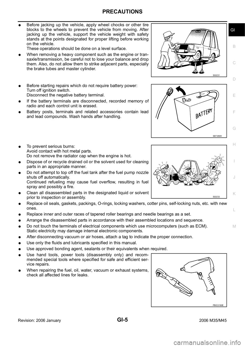
Before jacking up the vehicle, apply wheel chocks or other tire
blocks to the wheels to prevent the vehicle from moving. After
jacking up the vehicle, support the vehicle weight with safety
stands at the points designated for proper lifting before working
on the vehicle.
These operations should be done on a level surface.
When removing a heavy component such as the engine or tran-
saxle/transmission, be careful not to lose your balance and drop
them. Also, do not allow them to strike adjacent parts, especially
the brake tubes and master cylinder.
Before starting repairs which do not require battery power:
Turn off ignition switch.
Disconnect the negative battery terminal.
If the battery terminals are disconnected, recorded memory of
radio and each control unit is erased.
Battery posts, terminals and related accessories contain lead
and lead compounds. Wash hands after handling.
To prevent serious burns:
Avoid contact with hot metal parts.
Do not remove the radiator cap when the engine is hot.
Dispose of or recycle drained oil or the solvent used for cleaning
parts in an appropriate manner.
Do not attempt to top off the fuel tank after the fuel pump nozzle
shuts off automatically.
Continued refueling may cause fuel overflow, resulting in fuel
spray and possibly a fire.
Clean all disassembled parts in the designated liquid or solvent
prior to inspection or assembly.
Replace oil seals, gaskets, packings, O-rings, locking washers, cotter pins, self-locking nuts, etc. with new
ones.
Replace inner and outer races of tapered roller bearings and needle bearings as a set.
Arrange the disassembled parts in accordance with their assembled locations and sequence.
Do not touch the terminals of electrical components which use microcomputers (such as ECM).
Static electricity may damage internal electronic components.
After disconnecting vacuum or air hoses, attach a tag to indicate the proper connection.
Use only the fluids and lubricants specified in this manual.
Use approved bonding agent, sealants or their equivalents when required.
Use hand tools, power tools (disassembly only) and recom-
mended special tools where specified for safe and efficient ser-
vice repairs.
When repairing the fuel, oil, water, vacuum or exhaust systems,
check all affected lines for leaks.
SGI231
SEF289H
SGI233
PBIC0190E
Page 3500 of 5621
SERVICE INFORMATION FOR ELECTRICAL INCIDENT
GI-37
C
D
E
F
G
H
I
J
K
L
MB
GI
Revision: 2006 January2006 M35/M45
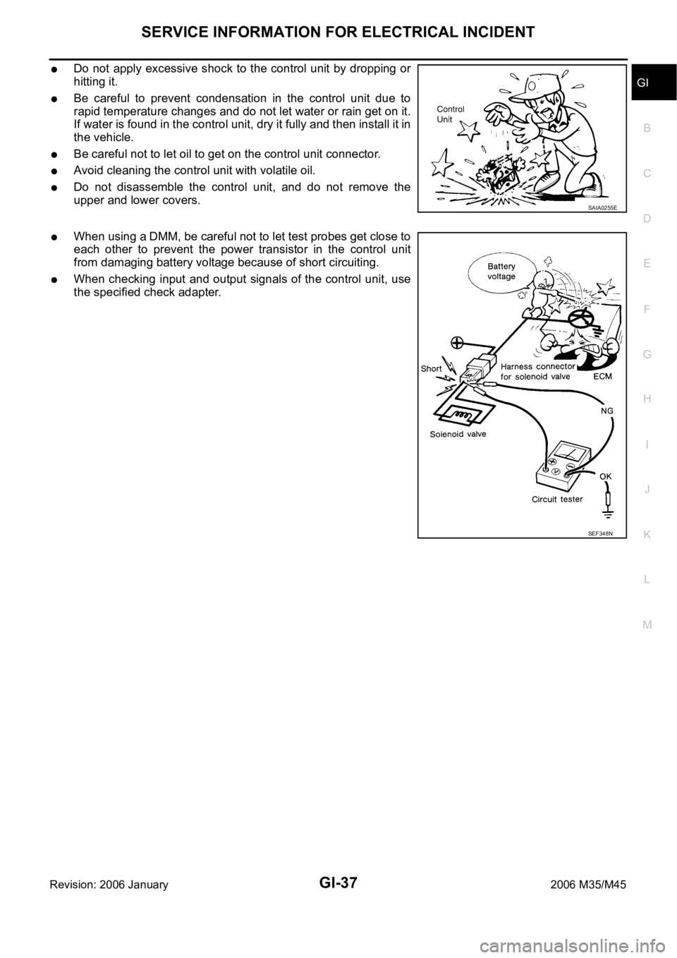
Do not apply excessive shock to the control unit by dropping or
hitting it.
Be careful to prevent condensation in the control unit due to
rapid temperature changes and do not let water or rain get on it.
If water is found in the control unit, dry it fully and then install it in
the vehicle.
Be careful not to let oil to get on the control unit connector.
Avoid cleaning the control unit with volatile oil.
Do not disassemble the control unit, and do not remove the
upper and lower covers.
When using a DMM, be careful not to let test probes get close to
each other to prevent the power transistor in the control unit
from damaging battery voltage because of short circuiting.
When checking input and output signals of the control unit, use
the specified check adapter.
SAIA0255E
SEF348N
Page 3613 of 5621
GW-94
REAR WINDOW DEFOGGER
Revision: 2006 January2006 M35/M45
Filament CheckNIS0022Y
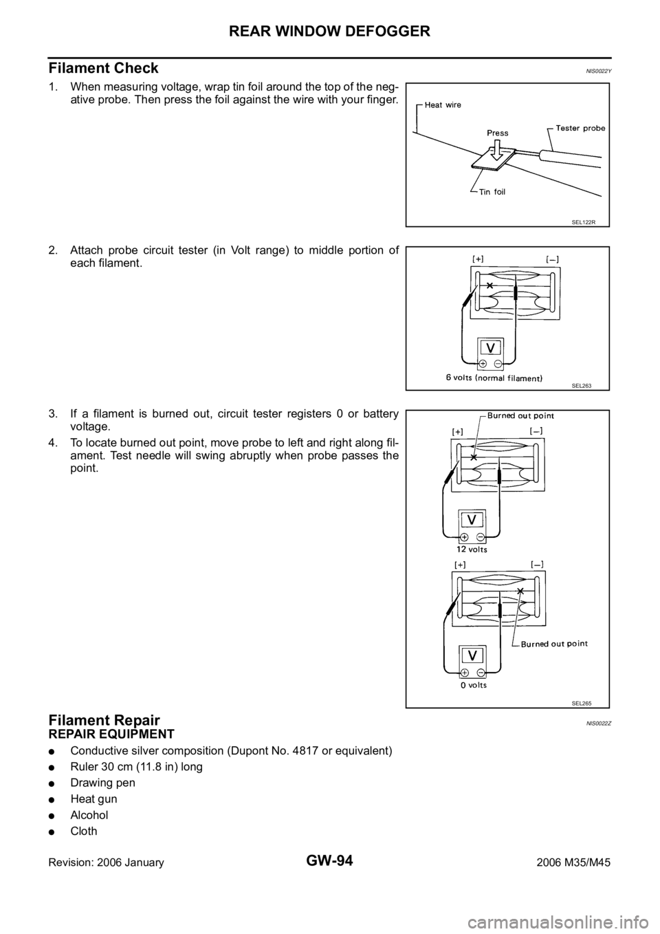
1. When measuring voltage, wrap tin foil around the top of the neg-
ative probe. Then press the foil against the wire with your finger.
2. Attach probe circuit tester (in Volt range) to middle portion of
each filament.
3. If a filament is burned out, circuit tester registers 0 or battery
voltage.
4. To locate burned out point, move probe to left and right along fil-
ament. Test needle will swing abruptly when probe passes the
point.
Filament RepairNIS0022Z
REPAIR EQUIPMENT
Conductive silver composition (Dupont No. 4817 or equivalent)
Ruler 30 cm (11.8 in) long
Drawing pen
Heat gun
Alcohol
Cloth
SEL122R
SEL263
SEL265
Page 3643 of 5621
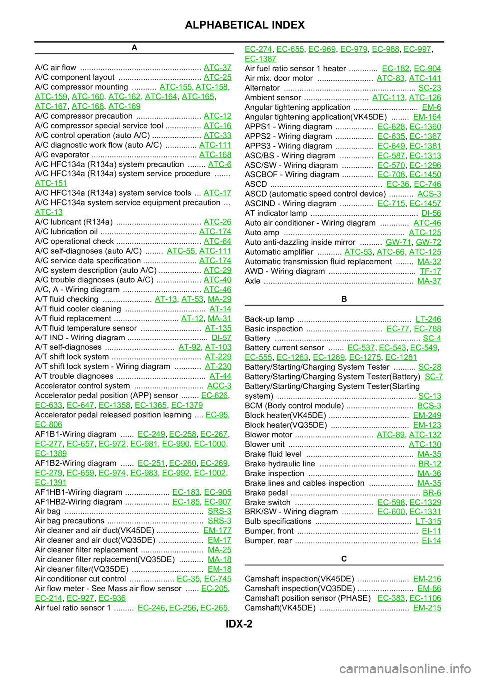
IDX-2
ALPHABETICAL INDEX
A
A/C air flow ...................................................... ATC-37
A/C component layout ..................................... ATC-25
A/C compressor mounting ........... ATC-155, ATC-158,
ATC-159
, ATC-160, ATC-162, ATC-164, ATC-165,
ATC-167
, ATC-168, ATC-169
A/C compressor precaution ............................. ATC-12
A/C compressor special service tool ................ ATC-16
A/C control operation (auto A/C) ...................... ATC-33
A/C diagnostic work flow (auto A/C) .............. ATC-111
A/C evaporator ............................................... ATC-168
A/C HFC134a (R134a) system precaution ........ ATC-6
A/C HFC134a (R134a) system service procedure .......
ATC-151
A/C HFC134a (R134a) system service tools ... ATC-17
A/C HFC134a system service equipment precaution ...
ATC-13
A/C lubricant (R134a) ...................................... ATC-26
A/C lubrication oil ........................................... ATC-174
A/C operational check ...................................... ATC-64
A/C self-diagnoses (auto A/C) ........ ATC-55, ATC-111
A/C service data specification ........................ ATC-174
A/C system description (auto A/C) ................... ATC-29
A/C trouble diagnoses (auto A/C) .................... ATC-40
A/C, A - Wiring diagram ................................... ATC-46
A/T fluid checking ...................... AT-13, AT-53, MA-29
A/T fluid cooler cleaning .................................... AT-14
A/T fluid replacement ............................. AT-12, MA-31
A/T fluid temperature sensor ........................... AT-135
A/T IND - Wiring diagram .................................... DI-57
A/T self-diagnoses ............................... AT-92, AT-103
A/T shift lock system ........................................ AT-229
A/T shift lock system - Wiring diagram ............ AT-230
A/T trouble diagnoses ........................................ AT-44
Accelerator control system ............................... ACC-3
Accelerator pedal position (APP) sensor ........ EC-626,
EC-633
, EC-647, EC-1358, EC-1365, EC-1379
Accelerator pedal released position learning .... EC-95,
EC-806
AF1B1-Wiring diagram ...... EC-249, EC-258, EC-267,
EC-277
, EC-657, EC-972, EC-981, EC-990, EC-1000,
EC-1389
AF1B2-Wiring diagram ...... EC-251, EC-260, EC-269,
EC-279
, EC-659, EC-974, EC-983, EC-992, EC-1002,
EC-1391
AF1HB1-Wiring diagram .................... EC-183, EC-905
AF1HB2-Wiring diagram .................... EC-185, EC-907
Air bag .............................................................. SRS-3
Air bag precautions ........................................... SRS-3
Air cleaner and air duct(VK45DE) ................... EM-177
Air cleaner and air duct(VQ35DE) .................... EM-17
Air cleaner filter replacement ............................ MA-25
Air cleaner filter replacement(VQ35DE) ........... MA-18
Air cleaner filter(VQ35DE) ................................ EM-18
Air conditioner cut control .................... EC-35, EC-745
Air flow meter - See Mass air flow sensor ...... EC-205,
EC-214
, EC-927, EC-936
Air fuel ratio sensor 1 ......... EC-246, EC-256, EC-265, EC-274
, EC-655, EC-969, EC-979, EC-988, EC-997,
EC-1387
Air fuel ratio sensor 1 heater ............. EC-182, EC-904
Air mix. door motor ......................... ATC-83, ATC-141
Alternator ........................................................... SC-23
Ambient sensor ............................. ATC-113, ATC-126
Angular tightening application ............................. EM-6
Angular tightening application(VK45DE) ........ EM-164
APPS1 - Wiring diagram ................. EC-628, EC-1360
APPS2 - Wiring diagram ................. EC-635, EC-1367
APPS3 - Wiring diagram ................. EC-649, EC-1381
ASC/BS - Wiring diagram ............... EC-587, EC-1313
ASC/SW - Wiring diagram .............. EC-570, EC-1296
ASCBOF - Wiring diagram .............. EC-708, EC-1450
ASCD .................................................. EC-36, EC-746
ASCD (automatic speed control device) ........... ACS-3
ASCIND - Wiring diagram ............... EC-715, EC-1457
AT indicator lamp ................................................ DI-56
Auto air conditioner - Wiring diagram ............. ATC-46
Auto amp ...................................................... ATC-125
Auto anti-dazzling inside mirror .......... GW-71, GW-72
Automatic amplifier ........... ATC-53, ATC-66, ATC-125
Automatic transmission fluid replacement ........ MA-32
AWD - Wiring diagram ....................................... TF-17
Axle ................................................................... MA-37
B
Back-up lamp ................................................... LT-246
Basic inspection .................................. EC-77, EC-788
Battery ................................................................. SC-4
Battery current sensor ....... EC-537, EC-543, EC-549,
EC-555
, EC-1263, EC-1269, EC-1275, EC-1281
Battery/Starting/Charging System Tester .......... SC-28
Battery/Starting/Charging System Tester(Battery) SC-7
Battery/Starting/Charging System Tester(Starting
system) .............................................................. SC-13
BCM (Body control module) .............................. BCS-3
Block heater(VK45DE) .................................... EM-249
Block heater(VQ35DE) ................................... EM-123
Blower motor ................................... ATC-89, ATC-132
Blower unit .................................................... ATC-130
Brake fluid level ................................................ MA-35
Brake hydraulic line ........................................... BR-12
Brake inspection ............................................... MA-36
Brake lines and cables inspection .................... MA-35
Brake pedal .......................................................... BR-6
Brake switch ................................... EC-598, EC-1329
BRK/SW - Wiring diagram .............. EC-600, EC-1331
Bulb specifications ........................................... LT-315
Bumper, front ...................................................... EI-11
Bumper, rear ....................................................... EI-14
C
Camshaft inspection(VK45DE) ....................... EM-216
Camshaft inspection(VQ35DE) ......................... EM-86
Camshaft position sensor (PHASE) EC-383, EC-1106
Camshaft(VK45DE) ........................................ EM-215
Page 3645 of 5621
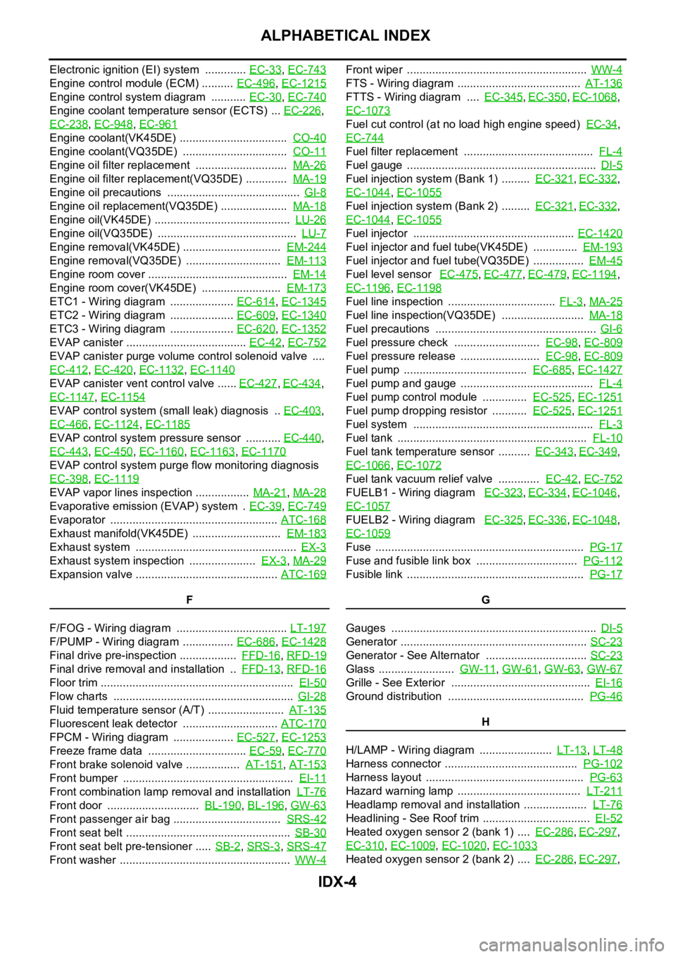
IDX-4
ALPHABETICAL INDEX
Electronic ignition (EI) system ............. EC-33, EC-743
Engine control module (ECM) .......... EC-496, EC-1215
Engine control system diagram ........... EC-30, EC-740
Engine coolant temperature sensor (ECTS) ... EC-226,
EC-238
, EC-948, EC-961
Engine coolant(VK45DE) .................................. CO-40
Engine coolant(VQ35DE) ................................. CO-11
Engine oil filter replacement ............................. MA-26
Engine oil filter replacement(VQ35DE) ............. MA-19
Engine oil precautions .......................................... GI-8
Engine oil replacement(VQ35DE) ..................... MA-18
Engine oil(VK45DE) ........................................... LU-26
Engine oil(VQ35DE) ............................................ LU-7
Engine removal(VK45DE) ............................... EM-244
Engine removal(VQ35DE) .............................. EM-113
Engine room cover ............................................ EM-14
Engine room cover(VK45DE) ......................... EM-173
ETC1 - Wiring diagram .................... EC-614, EC-1345
ETC2 - Wiring diagram .................... EC-609, EC-1340
ETC3 - Wiring diagram .................... EC-620, EC-1352
EVAP canister ...................................... EC-42, EC-752
EVAP canister purge volume control solenoid valve ....
EC-412
, EC-420, EC-1132, EC-1140
EVAP canister vent control valve ...... EC-427, EC-434,
EC-1147
, EC-1154
EVAP control system (small leak) diagnosis .. EC-403,
EC-466
, EC-1124, EC-1185
EVAP control system pressure sensor ........... EC-440,
EC-443
, EC-450, EC-1160, EC-1163, EC-1170
EVAP control system purge flow monitoring diagnosis
EC-398
, EC-1119
EVAP vapor lines inspection ................. MA-21, MA-28
Evaporative emission (EVAP) system . EC-39, EC-749
Evaporator ..................................................... ATC-168
Exhaust manifold(VK45DE) ............................ EM-183
Exhaust system ................................................... EX-3
Exhaust system inspection ..................... EX-3, MA-29
Expansion valve ............................................. ATC-169
F
F/FOG - Wiring diagram ................................... LT-197
F/PUMP - Wiring diagram ................ EC-686, EC-1428
Final drive pre-inspection .................. FFD-16, RFD-19
Final drive removal and installation .. FFD-13, RFD-16
Floor trim ............................................................. EI-50
Flow charts ......................................................... GI-28
Fluid temperature sensor (A/T) ........................ AT-135
Fluorescent leak detector .............................. ATC-170
FPCM - Wiring diagram ................... EC-527, EC-1253
Freeze frame data ............................... EC-59, EC-770
Front brake solenoid valve ................. AT-151, AT-153
Front bumper ...................................................... EI-11
Front combination lamp removal and installation LT-76
Front door ............................. BL-190, BL-196, GW-63
Front passenger air bag .................................. SRS-42
Front seat belt .................................................... SB-30
Front seat belt pre-tensioner ..... SB-2, SRS-3, SRS-47
Front washer ...................................................... WW-4
Front wiper ......................................................... WW-4
FTS - Wiring diagram ....................................... AT-136
FTTS - Wiring diagram .... EC-345, EC-350, EC-1068,
EC-1073
Fuel cut control (at no load high engine speed) EC-34,
EC-744
Fuel filter replacement ......................................... FL-4
Fuel gauge ............................................................ DI-5
Fuel injection system (Bank 1) ......... EC-321, EC-332,
EC-1044
, EC-1055
Fuel injection system (Bank 2) ......... EC-321, EC-332,
EC-1044
, EC-1055
Fuel injector ................................................... EC-1420
Fuel injector and fuel tube(VK45DE) .............. EM-193
Fuel injector and fuel tube(VQ35DE) ................ EM-45
Fuel level sensor EC-475, EC-477, EC-479, EC-1194,
EC-1196
, EC-1198
Fuel line inspection .................................. FL-3, MA-25
Fuel line inspection(VQ35DE) .......................... MA-18
Fuel precautions ................................................... GI-6
Fuel pressure check ........................... EC-98, EC-809
Fuel pressure release ......................... EC-98, EC-809
Fuel pump ....................................... EC-685, EC-1427
Fuel pump and gauge .......................................... FL-4
Fuel pump control module .............. EC-525, EC-1251
Fuel pump dropping resistor ........... EC-525, EC-1251
Fuel system ......................................................... FL-3
Fuel tank ............................................................ FL-10
Fuel tank temperature sensor .......... EC-343, EC-349,
EC-1066
, EC-1072
Fuel tank vacuum relief valve ............. EC-42, EC-752
FUELB1 - Wiring diagram EC-323, EC-334, EC-1046,
EC-1057
FUELB2 - Wiring diagram EC-325, EC-336, EC-1048,
EC-1059
Fuse .................................................................. PG-17
Fuse and fusible link box ................................ PG-112
Fusible link ........................................................ PG-17
G
Gauges ................................................................. DI-5
Generator ........................................................... SC-23
Generator - See Alternator ................................ SC-23
Glass ........................ GW-11, GW-61, GW-63, GW-67
Grille - See Exterior ............................................ EI-16
Ground distribution ........................................... PG-46
H
H/LAMP - Wiring diagram ....................... LT-13
, LT-48
Harness connector .......................................... PG-102
Harness layout .................................................. PG-63
Hazard warning lamp ....................................... LT-211
Headlamp removal and installation .................... LT-76
Headlining - See Roof trim .................................. EI-52
Heated oxygen sensor 2 (bank 1) .... EC-286, EC-297,
EC-310
, EC-1009, EC-1020, EC-1033
Heated oxygen sensor 2 (bank 2) .... EC-286, EC-297,