Page 982 of 5621
POWER DOOR LOCK SYSTEM
BL-43
C
D
E
F
G
H
J
K
L
MA
B
BL
Revision: 2006 January2006 M35/M45
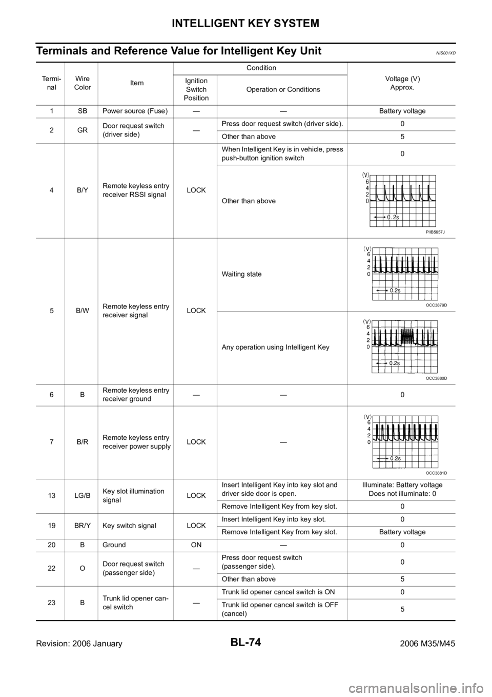
3. CHECK DOOR KEY CYLINDER SWITCH GROUND
Check continuity between front door lock assembly (driver side) connector ground.
OK or NG
OK >> GO TO 4.
NG >> Repair or replace harness.
4. CHECK DOOR KEY CYLINDER SWITCH
Check front door lock assembly (driver side).
OK or NG
OK >> INSPECTION END.
NG >> Replace front door key cylinder (driver side) switch.
Front door lock
assembly
(driver side)
connectorTerminal Continuity
D14 4 Ground Yes
PIIB5974E
Terminal
Key position Continuity
Front door lock assembly
(driver side)
5
4Unlock Yes
Neutral / Lock No
6Lock Yes
Neutral / Unlock No
PIIB5975E
Page 1013 of 5621

BL-74
INTELLIGENT KEY SYSTEM
Revision: 2006 January2006 M35/M45
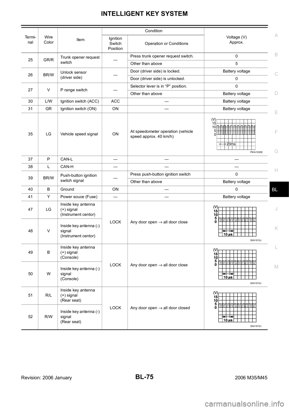
Terminals and Reference Value for Intelligent Key UnitNIS001XD
Te r m i -
nalWire
ColorItemCondition
Voltage (V)
Approx. Ignition
Switch
PositionOperation or Conditions
1 SB Power source (Fuse) — — Battery voltage
2GRDoor request switch
(driver side)—Press door request switch (driver side). 0
Other than above 5
4B/YRemote keyless entry
receiver RSSI signalLOCKWhen Intelligent Key is in vehicle, press
push-button ignition switch0
Other than above
5B/WRemote keyless entry
receiver signalLOCKWaiting state
Any operation using Intelligent Key
6BRemote keyless entry
receiver ground—— 0
7B/RRemote keyless entry
receiver power supplyLOCK —
13 LG/BKey slot illumination
signalLOCKInsert Intelligent Key into key slot and
driver side door is open.Illuminate: Battery voltage
Does not illuminate: 0
Remove Intelligent Key from key slot. 0
19 BR/Y Key switch signal LOCKInsert Intelligent Key into key slot. 0
Remove Intelligent Key from key slot. Battery voltage
20 B Ground ON — 0
22 ODoor request switch
(passenger side)—Press door request switch
(passenger side).0
Other than above 5
23 BTrunk lid opener can-
cel switch—Trunk lid opener cancel switch is ON 0
Trunk lid opener cancel switch is OFF
(cancel)5
PIIB5657J
OCC3879D
OCC3880D
OCC3881D
Page 1014 of 5621

INTELLIGENT KEY SYSTEM
BL-75
C
D
E
F
G
H
J
K
L
MA
B
BL
Revision: 2006 January2006 M35/M45
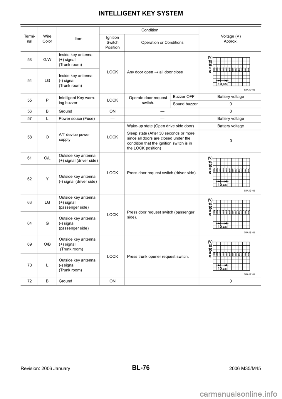
25 GR/RTrunk opener request
switch—Press trunk opener request switch. 0
Other than above 5
26 BR/WUnlock sensor
(driver side)—Door (driver side) is locked. Battery voltage
Door (driver side) is unlocked. 0
27 V P range switch —Selector lever is in “P” position. 0
Other than above Battery voltage
30 L/W Ignition switch (ACC) ACC — Battery voltage
31 GR Ignition switch (ON) ON — Battery voltage
35 LG Vehicle speed signal ONAt speedometer operation (vehicle
speed approx. 40 km/h)
37 P CAN-L — — —
38 L CAN-H — — —
39 BR/WPush-button ignition
switch signal—Press push-button ignition switch 0
Other than above Battery voltage
40 B Ground ON — 0
41 Y Power souce (Fuse) — — Battery voltage
47 LGInside key antenna
(+) signal
(Instrument centor)
LOCK Any door open
all door close
48 VInside key antenna (-)
signal
(Instrument centor)
49 BInside key antenna
(+) signal
(Console)
LOCK Any door open
all door close
50 WInside key antenna (-)
signal
(Console)
51 R/LInside key antenna
(+) signal
(Rear seat)
LOCK Any door open
all door closed
52 R/WInside key antenna (-)
signal
(Rear seat) Te r m i -
nalWire
ColorItemCondition
Voltage (V)
Approx. Ignition
Switch
PositionOperation or Conditions
PKIA1935E
SIIA1910J
SIIA1910J
SIIA1910J
Page 1015 of 5621

BL-76
INTELLIGENT KEY SYSTEM
Revision: 2006 January2006 M35/M45
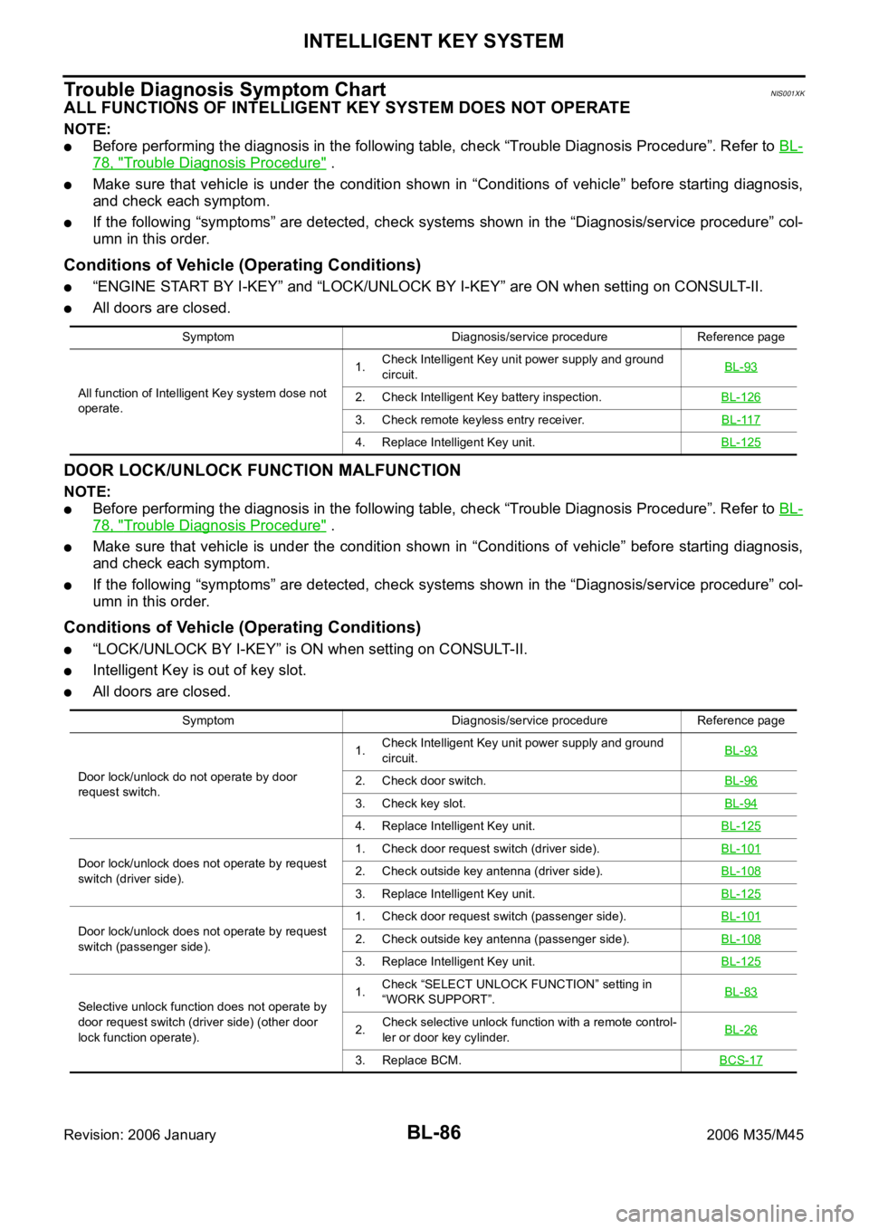
53 G/WInside key antenna
(+) signal
(Trunk room)
LOCK Any door open
all door close
54 LGInside key antenna
(-) signal
(Trunk room)
55 PIntelligent Key warn-
ing buzzerLOCKOperate door request
switch.Buzzer OFF Battery voltage
Sound buzzer 0
56 B Ground ON — 0
57 L Power souce (Fuse) — — Battery voltage
58 OA/T device power
supply LOCKWake-up state (Open drive side door) Battery voltage
Sleep state (After 30 seconds or more
since all doors are closed under the
condition that the ignition switch is in
the LOCK position)0
61 O/LOutside key antenna
(+) signal (driver side)
LOCK Press door request switch (driver side).
62 YOutside key antenna
(-) signal (driver side)
63 LGOutside key antenna
(+) signal
(passenger side)
LOCKPress door request switch (passenger
side).
64 GOutside key antenna
(-) signal
(passenger side)
69 O/BOutside key antenna
(+) signal
(Trunk room)
LOCK Press trunk opener request switch.
70 LOutside key antenna
(-) signal
(Trunk room)
72 B Ground ON 0 Te r m i -
nalWire
ColorItemCondition
Voltage (V)
Approx. Ignition
Switch
PositionOperation or Conditions
SIIA1910J
SIIA1910J
SIIA1910J
SIIA1910J
Page 1016 of 5621

INTELLIGENT KEY SYSTEM
BL-77
C
D
E
F
G
H
J
K
L
MA
B
BL
Revision: 2006 January2006 M35/M45
Terminals and Reference Value for BCMNIS001XE
*1: In the state that hazard reminder operates.
*2: In the state that room lamp switch is in “DOOR” position.
Terminals and Reference Value for IPDM E/RNIS001XF
Te r m i -
nalWire
ColorItem ConditionVoltage (V)
Approx.
11 V Ignition switch (ACC) Ignition switch is in ACC or ON position Battery voltage
12 PFront door switch passenger
sideDoor open (ON)
Close (OFF) 0 8
13 O/L Rear door switch RH Door open (ON)
Close (OFF) 0 Battery voltage
37 LG Key switch signalInsert Intelligent Key into key slot. Battery voltage
Remove Intelligent Key from key slot. 0
38 W Ignition switch (ON)Ignition switch is in ON or START posi-
tion.Battery voltage
39 L CAN-H — —
40 P CAN-L — —
42 P Power supply (fuse) — Battery voltage
52 B Ground — 0
55 W Power supply (Fusible link) — Battery voltage
57 SB Trunk room lamp switch Trunk lid open (ON)
Close (OFF) 0 Battery voltage
62 V Front door switch driver side Door open (ON)
Close (OFF) 0 Battery voltage
63 R/G Rear door switch LH Door open (ON)
Close (OFF) 0 Battery voltage
Te r m i n a l Wire
ColorItem ConditionVoltage (V)
Approx.
48 G/B Horn relay Press panic alarm bottom.Horn sounds. 0
Horn does not sound. Battery voltage
49 L CAN-H — —
50 P CAN-L — —
Page 1025 of 5621

BL-86
INTELLIGENT KEY SYSTEM
Revision: 2006 January2006 M35/M45
Trouble Diagnosis Symptom ChartNIS001XK
ALL FUNCTIONS OF INTELLIGENT KEY SYSTEM DOES NOT OPERATE
NOTE:
Before performing the diagnosis in the following table, check “Trouble Diagnosis Procedure”. Refer to BL-
78, "Trouble Diagnosis Procedure" .
Make sure that vehicle is under the condition shown in “Conditions of vehicle” before starting diagnosis,
and check each symptom.
If the following “symptoms” are detected, check systems shown in the “Diagnosis/service procedure” col-
umn in this order.
Conditions of Vehicle (Operating Conditions)
“ENGINE START BY I-KEY” and “LOCK/UNLOCK BY I-KEY” are ON when setting on CONSULT-II.
All doors are closed.
DOOR LOCK/UNLOCK FUNCTION MALFUNCTION
NOTE:
Before performing the diagnosis in the following table, check “Trouble Diagnosis Procedure”. Refer to BL-
78, "Trouble Diagnosis Procedure" .
Make sure that vehicle is under the condition shown in “Conditions of vehicle” before starting diagnosis,
and check each symptom.
If the following “symptoms” are detected, check systems shown in the “Diagnosis/service procedure” col-
umn in this order.
Conditions of Vehicle (Operating Conditions)
“LOCK/UNLOCK BY I-KEY” is ON when setting on CONSULT-II.
Intelligent Key is out of key slot.
All doors are closed.
Symptom Diagnosis/service procedure Reference page
All function of Intelligent Key system dose not
operate.1.Check Intelligent Key unit power supply and ground
circuit.BL-93
2. Check Intelligent Key battery inspection.BL-126
3. Check remote keyless entry receiver.BL-117
4. Replace Intelligent Key unit.BL-125
Symptom Diagnosis/service procedure Reference page
Door lock/unlock do not operate by door
request switch.1.Check Intelligent Key unit power supply and ground
circuit.BL-93
2. Check door switch.BL-96
3. Check key slot.BL-94
4. Replace Intelligent Key unit.BL-125
Door lock/unlock does not operate by request
switch (driver side).1. Check door request switch (driver side).BL-1012. Check outside key antenna (driver side).BL-108
3. Replace Intelligent Key unit.BL-125
Door lock/unlock does not operate by request
switch (passenger side).1. Check door request switch (passenger side).BL-1012. Check outside key antenna (passenger side).BL-108
3. Replace Intelligent Key unit.BL-125
Selective unlock function does not operate by
door request switch (driver side) (other door
lock function operate).1.Check “SELECT UNLOCK FUNCTION” setting in
“WORK SUPPORT”.BL-83
2.Check selective unlock function with a remote control-
ler or door key cylinder.BL-26
3. Replace BCM.BCS-17
Page 1032 of 5621
INTELLIGENT KEY SYSTEM
BL-93
C
D
E
F
G
H
J
K
L
MA
B
BL
Revision: 2006 January2006 M35/M45
Check Power Supply and Ground CircuitNIS001XM
1. CHECK POWER SUPPLY CIRCUIT
1. Turn ignition switch OFF.
2. Disconnect Intelligent Key unit connector.
3. Check voltage between Intelligent Key unit harness connector and ground.
OK or NG
OK >> GO TO 2.
NG >> Repair or replace Intelligent Key power supply circuit.
2. CHECK GROUND CIRCUIT
Check continuity between Intelligent Key unit harness connector and ground.
OK or NG
OK >> Power supply and ground circuits are OK.
NG >> Repair or replace the Intelligent Key unit ground circuit.
Terminals
Voltage (V)
(Approx.) (+)
(–)
Intelligent Key unit
connectorTerminal
M32 1
Ground Battery voltage
M3341
57
PIIB6251E
Intelligent Key unit connector Terminal
GroundContinuity
M3220
Ye s 40
M3356
72
PIIB6318E
Page 1033 of 5621
BL-94
INTELLIGENT KEY SYSTEM
Revision: 2006 January2006 M35/M45
Check Key SlotNIS001XN
1. CHECK KEY SLOT INPUT SIGNAL
Check voltage between Intelligent Key unit harness connector and ground.
OK or NG
OK >> Key slot is OK.
NG >> GO TO 2.
2. CHECK KEY SLOT POWER SUPPLY CIRCUIT
1. Turn ignition switch OFF.
2. Disconnect key slot connector.
3. Check voltage between slot connector and ground.
OK or NG
OK >> GO TO 3.
NG >> Repair or replace key slot power supply circuit.
3. CHECK KEY SLOT
Check key slot.
OK or NG
OK >> GO TO 4.
NG >> Replace key slot.
Terminals
ConditionVoltage (V)
(Approx.) (+)
(–)
Intelligent Key
unit connectorTerminal
M32 19 GroundIntelligent Key inserted Battery voltage
Intelligent Key removed 0
PIIB6319E
Terminals
Voltage (V)
(Approx.) (+)
(–)
Key slot connector Terminal
M14 1 Ground Battery voltage
PIIB6320E
Terminal
Condition Continuity
Key slot
13Intelligent Key inserted Yes
Intelligent Key removed No
PIIB6321E