Page 1058 of 5621
INTELLIGENT KEY SYSTEM
BL-119
C
D
E
F
G
H
J
K
L
MA
B
BL
Revision: 2006 January2006 M35/M45
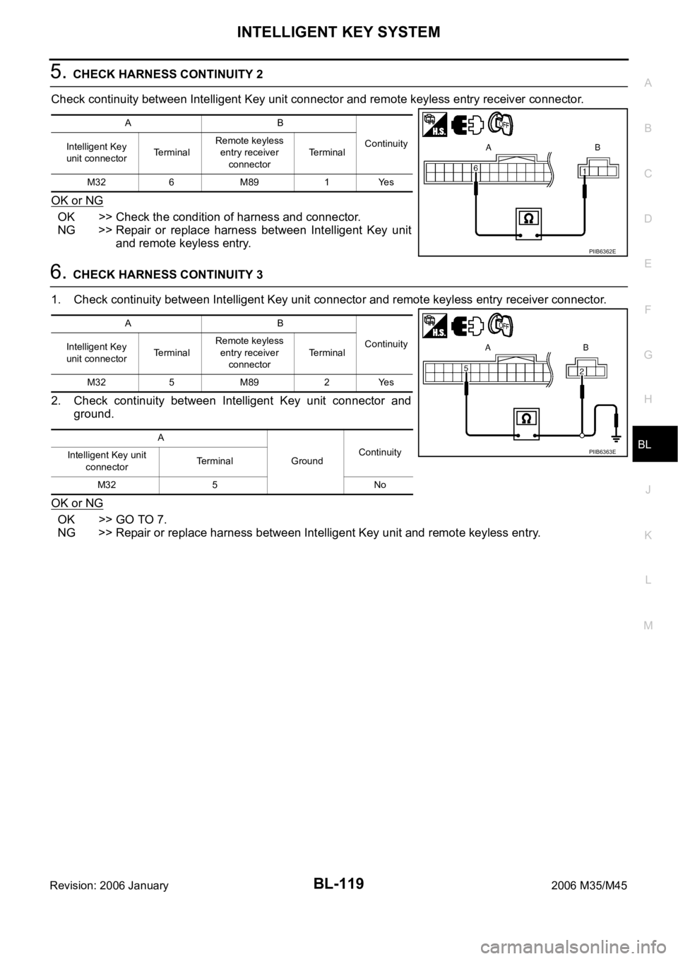
5. CHECK HARNESS CONTINUITY 2
Check continuity between Intelligent Key unit connector and remote keyless entry receiver connector.
OK or NG
OK >> Check the condition of harness and connector.
NG >> Repair or replace harness between Intelligent Key unit
and remote keyless entry.
6. CHECK HARNESS CONTINUITY 3
1. Check continuity between Intelligent Key unit connector and remote keyless entry receiver connector.
2. Check continuity between Intelligent Key unit connector and
ground.
OK or NG
OK >> GO TO 7.
NG >> Repair or replace harness between Intelligent Key unit and remote keyless entry.
AB
Continuity
Intelligent Key
unit connectorTerminalRemote keyless
entry receiver
connectorTerminal
M32 6 M89 1 Yes
PIIB6362E
AB
Continuity
Intelligent Key
unit connectorTerminalRemote keyless
entry receiver
connectorTerminal
M32 5 M89 2 Yes
A
GroundContinuity
Intelligent Key unit
connectorTerminal
M32 5 No
PIIB6363E
Page 1059 of 5621
BL-120
INTELLIGENT KEY SYSTEM
Revision: 2006 January2006 M35/M45
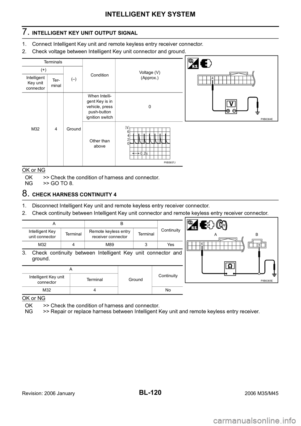
7. INTELLIGENT KEY UNIT OUTPUT SIGNAL
1. Connect Intelligent Key unit and remote keyless entry receiver connector.
2. Check voltage between Intelligent Key unit connector and ground.
OK or NG
OK >> Check the condition of harness and connector.
NG >> GO TO 8.
8. CHECK HARNESS CONTINUITY 4
1. Disconnect Intelligent Key unit and remote keyless entry receiver connector.
2. Check continuity between Intelligent Key unit connector and remote keyless entry receiver connector.
3. Check continuity between Intelligent Key unit connector and
ground.
OK or NG
OK >> Check the condition of harness and connector.
NG >> Repair or replace harness between Intelligent Key unit and remote keyless entry receiver.
Terminals
ConditionVoltage (V)
(Approx.) (+)
(–) Intelligent
Key unit
connectorTe r -
minal
M32 4 GroundWhen Intelli-
gent Key is in
vehicle, press
push-button
ignition switch0
Other than
above
PIIB6364E
PIIB5657J
AB
Continuity
Intelligent Key
unit connectorTerminalRemote keyless entry
receiver connectorTerminal
M32 4 M89 3 Yes
A
GroundContinuity
Intelligent Key unit
connectorTerminal
M32 4 No
PIIB6365E
Page 1060 of 5621
INTELLIGENT KEY SYSTEM
BL-121
C
D
E
F
G
H
J
K
L
MA
B
BL
Revision: 2006 January2006 M35/M45
Check Trunk Lid Opener Cancel SwitchNIS001Y0
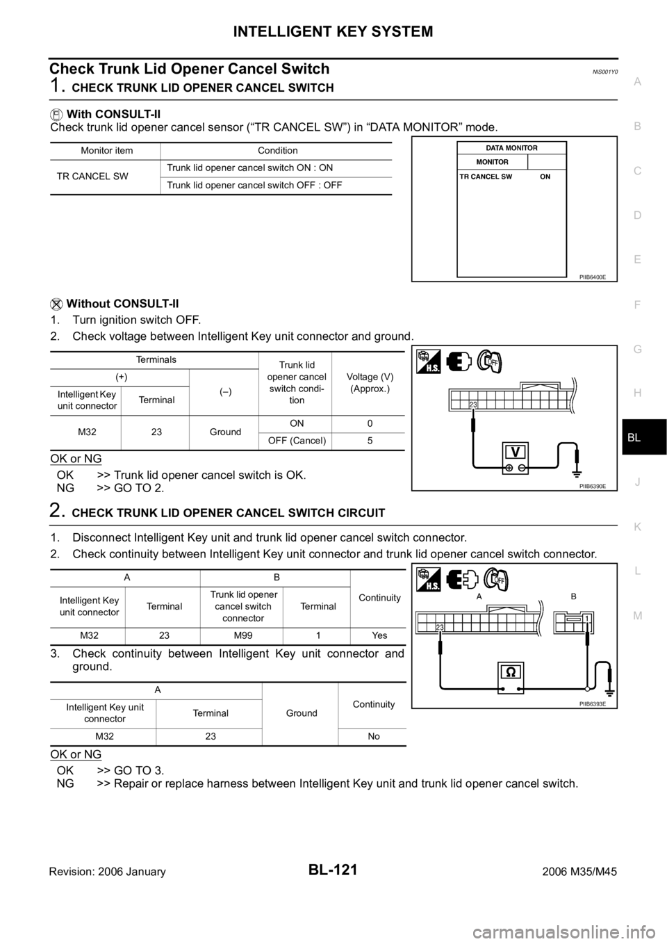
1. CHECK TRUNK LID OPENER CANCEL SWITCH
With CONSULT-II
Check trunk lid opener cancel sensor (“TR CANCEL SW”) in “DATA MONITOR” mode.
Without CONSULT-II
1. Turn ignition switch OFF.
2. Check voltage between Intelligent Key unit connector and ground.
OK or NG
OK >> Trunk lid opener cancel switch is OK.
NG >> GO TO 2.
2. CHECK TRUNK LID OPENER CANCEL SWITCH CIRCUIT
1. Disconnect Intelligent Key unit and trunk lid opener cancel switch connector.
2. Check continuity between Intelligent Key unit connector and trunk lid opener cancel switch connector.
3. Check continuity between Intelligent Key unit connector and
ground.
OK or NG
OK >> GO TO 3.
NG >> Repair or replace harness between Intelligent Key unit and trunk lid opener cancel switch.
Monitor item Condition
TR CANCEL SWTrunk lid opener cancel switch ON : ON
Trunk lid opener cancel switch OFF : OFF
PIIB6400E
Terminals
Trunk lid
opener cancel
switch condi-
tionVoltage (V)
(Approx.) (+)
(–)
Intelligent Key
unit connectorTerminal
M32 23 GroundON 0
OFF (Cancel) 5
PIIB6390E
AB
Continuity
Intelligent Key
unit connectorTe r m i n a l Trunk lid opener
cancel switch
connectorTerminal
M32 23 M99 1 Yes
A
GroundContinuity
Intelligent Key unit
connectorTerminal
M32 23 No
PIIB6393E
Page 1061 of 5621
BL-122
INTELLIGENT KEY SYSTEM
Revision: 2006 January2006 M35/M45
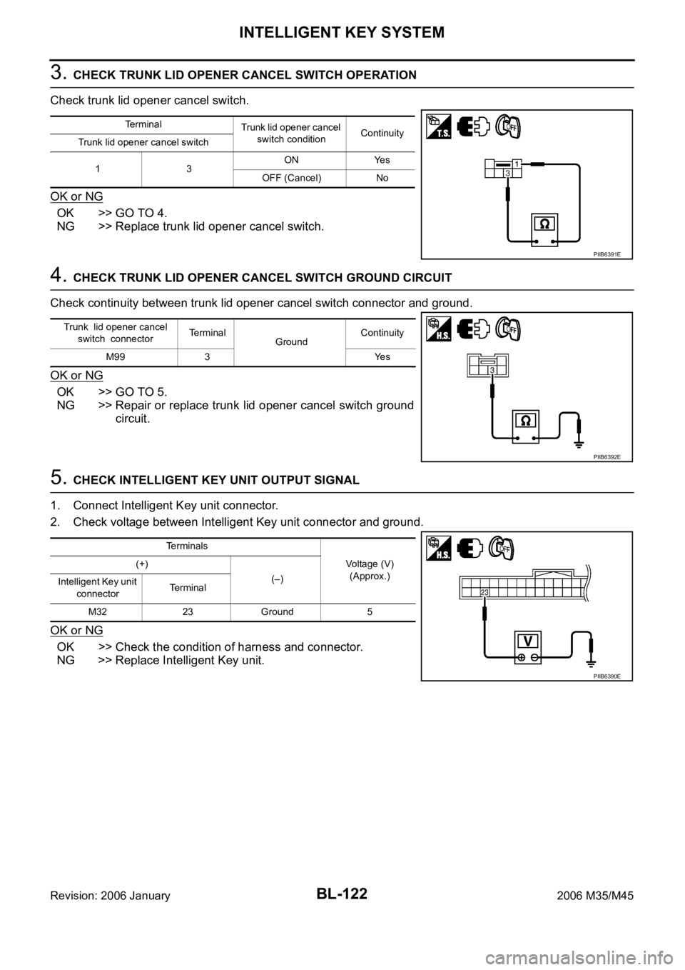
3. CHECK TRUNK LID OPENER CANCEL SWITCH OPERATION
Check trunk lid opener cancel switch.
OK or NG
OK >> GO TO 4.
NG >> Replace trunk lid opener cancel switch.
4. CHECK TRUNK LID OPENER CANCEL SWITCH GROUND CIRCUIT
Check continuity between trunk lid opener cancel switch connector and ground.
OK or NG
OK >> GO TO 5.
NG >> Repair or replace trunk lid opener cancel switch ground
circuit.
5. CHECK INTELLIGENT KEY UNIT OUTPUT SIGNAL
1. Connect Intelligent Key unit connector.
2. Check voltage between Intelligent Key unit connector and ground.
OK or NG
OK >> Check the condition of harness and connector.
NG >> Replace Intelligent Key unit.
Terminal
Trunk lid opener cancel
switch conditionContinuity
Trunk lid opener cancel switch
13ON Yes
OFF (Cancel) No
PIIB6391E
Trunk lid opener cancel
switch connectorTerminal
GroundContinuity
M99 3 Yes
PIIB6392E
Terminals
Voltage (V)
(Approx.) (+)
(–)
Intelligent Key unit
connectorTerminal
M32 23 Ground 5
PIIB6390E
Page 1062 of 5621
INTELLIGENT KEY SYSTEM
BL-123
C
D
E
F
G
H
J
K
L
MA
B
BL
Revision: 2006 January2006 M35/M45
Check Key Slot IlluminationNIS001Y1
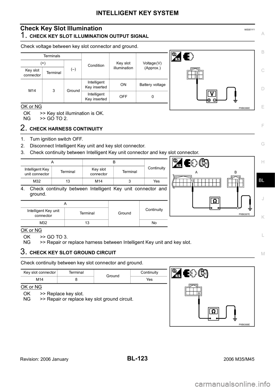
1. CHECK KEY SLOT ILLUMINATION OUTPUT SIGNAL
Check voltage between key slot connector and ground.
OK or NG
OK >> Key slot illumination is OK.
NG >> GO TO 2.
2. CHECK HARNESS CONTINUITY
1. Turn ignition switch OFF.
2. Disconnect Intelligent Key unit and key slot connector.
3. Check continuity between Intelligent Key unit connector and key slot connector.
4. Check continuity between Intelligent Key unit connector and
ground.
OK or NG
OK >> GO TO 3.
NG >> Repair or replace harness between Intelligent Key unit and key slot.
3. CHECK KEY SLOT GROUND CIRCUIT
Check continuity between key slot connector and ground.
OK or NG
OK >> Replace key slot.
NG >> Repair or replace key slot ground circuit.
Terminals
ConditionKey slot
illuminationV o l t a g e ( V )
(Approx.) (+)
(–)
Key slot
connectorTe r m i n a l
M14 3 GroundIntelligent
Key insertedON Battery voltage
Intelligent
Key insertedOFF 0
PIIB6366E
AB
Continuity
Intelligent Key
unit connectorTe r m i n a lKey slot
connectorTe r m i n a l
M32 13 M14 3 Yes
A
GroundContinuity
Intelligent Key unit
connectorTerminal
M32 13 No
PIIB6367E
Key slot connector Terminal
GroundContinuity
M14 8 Yes
PIIB6368E
Page 1063 of 5621
BL-124
INTELLIGENT KEY SYSTEM
Revision: 2006 January2006 M35/M45
Check Horn FunctionNIS001Y2
First perform the “SELF-DIAG RESULTS” of “BCM” with CONSULT-II, then perform the trouble diagno-
sis of malfunction system indicated in “SELF-DIAG RESULTS” of “BCM”. Refer to BCS-15, "
CAN Com-
munication Inspection Using CONSULT-II (Self-Diagnosis)".
1. CHECK HORN OPERATION
Check if horn sounds with horn switch.
Does horn operate?
Yes >> GO TO 2.
No >> Check horn circuit. Refer to WW-53, "
HORN" .
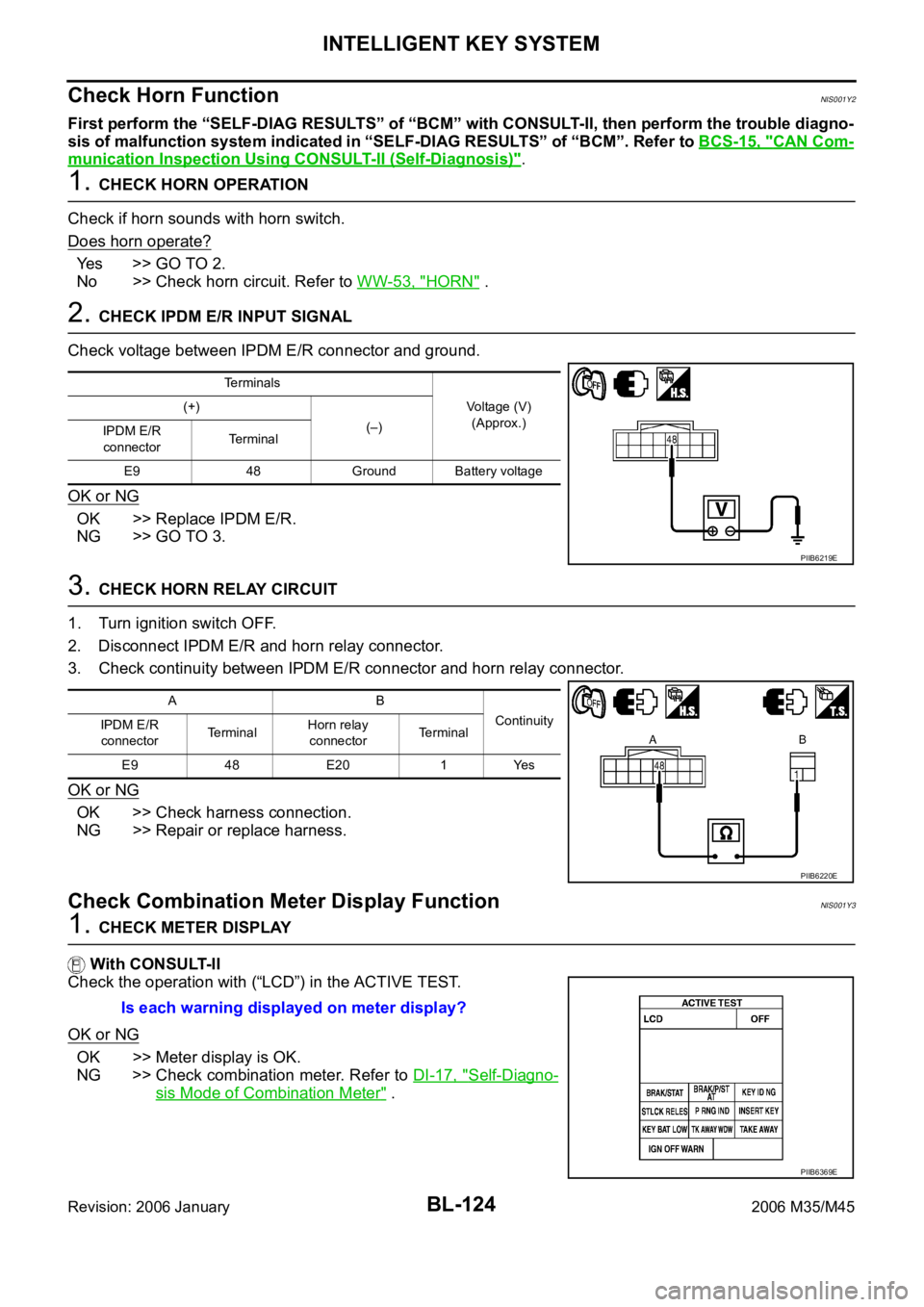
2. CHECK IPDM E/R INPUT SIGNAL
Check voltage between IPDM E/R connector and ground.
OK or NG
OK >> Replace IPDM E/R.
NG >> GO TO 3.
3. CHECK HORN RELAY CIRCUIT
1. Turn ignition switch OFF.
2. Disconnect IPDM E/R and horn relay connector.
3. Check continuity between IPDM E/R connector and horn relay connector.
OK or NG
OK >> Check harness connection.
NG >> Repair or replace harness.
Check Combination Meter Display FunctionNIS001Y3
1. CHECK METER DISPLAY
With CONSULT-II
Check the operation with (“LCD”) in the ACTIVE TEST.
OK or NG
OK >> Meter display is OK.
NG >> Check combination meter. Refer to DI-17, "
Self-Diagno-
sis Mode of Combination Meter" .
Terminals
Voltage (V)
(Approx.) (+)
(–)
IPDM E/R
connectorTerminal
E9 48 Ground Battery voltage
PIIB6219E
AB
Continuity
IPDM E/R
connectorTe r m i n a lHorn relay
connectorTerminal
E9 48 E20 1 Yes
PIIB6220E
Is each warning displayed on meter display?
PIIB6369E
Page 1082 of 5621
INTELLIGENT KEY SYSTEM/ENGINE START FUNCTION
BL-143
C
D
E
F
G
H
J
K
L
MA
B
BL
Revision: 2006 January2006 M35/M45
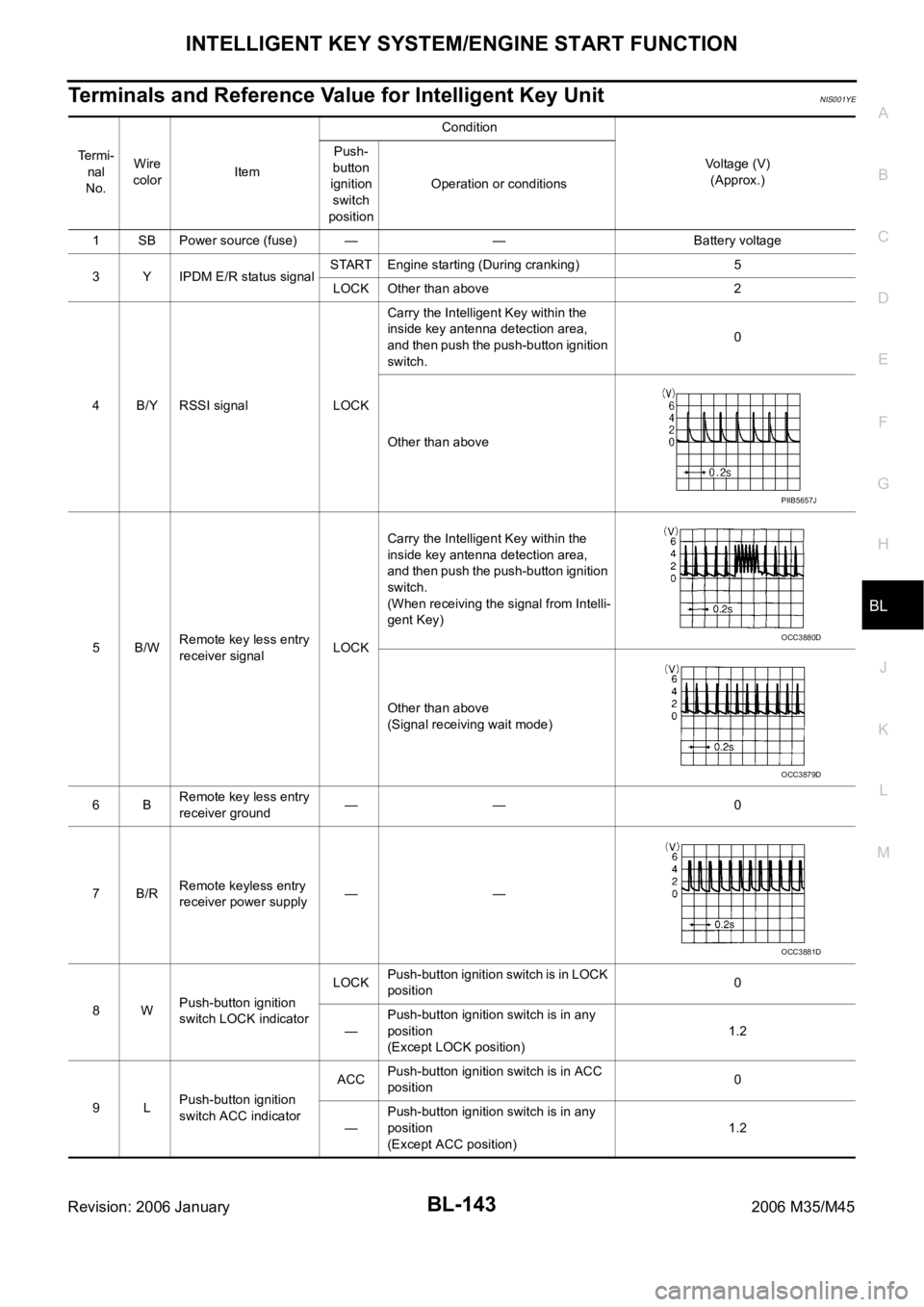
Terminals and Reference Value for Intelligent Key UnitNIS001YE
Te r m i -
nal
No.Wire
colorItemCondition
Voltage (V)
(Approx.) Push-
button
ignition
switch
positionOperation or conditions
1 SB Power source (fuse) — — Battery voltage
3 Y IPDM E/R status signalSTART Engine starting (During cranking) 5
LOCK Other than above 2
4 B/Y RSSI signal LOCKCarry the Intelligent Key within the
inside key antenna detection area,
and then push the push-button ignition
switch.0
Other than above
5B/WRemote key less entry
receiver signalLOCKCarry the Intelligent Key within the
inside key antenna detection area,
and then push the push-button ignition
switch.
(When receiving the signal from Intelli-
gent Key)
Other than above
(Signal receiving wait mode)
6BRemote key less entry
receiver ground—— 0
7B/RRemote keyless entry
receiver power supply——
8WPush-button ignition
switch LOCK indicatorLOCKPush-button ignition switch is in LOCK
position0
—Push-button ignition switch is in any
position
(Except LOCK position)1.2
9LPush-button ignition
switch ACC indicatorACCPush-button ignition switch is in ACC
position0
—Push-button ignition switch is in any
position
(Except ACC position)1.2
PIIB5657J
OCC3880D
OCC3879D
OCC3881D
Page 1083 of 5621

BL-144
INTELLIGENT KEY SYSTEM/ENGINE START FUNCTION
Revision: 2006 January2006 M35/M45
10 VPush-button ignition
switch ON indicatorONPush-button ignition switch is in ON
position0
—Push-button ignition switch is in any
position
(Except ON position)1.2
11 P Stop lamp switch —Brake pedal depressed Battery voltage
Brake pedal released Battery voltage
12 L/RPush-button ignition
switch illumination—Push-button ignition switch illumina-
tion is turned on2.6
Push-button ignition switch illumina-
tion is turned off
(15 seconds or more after the driver
door is closed)0
13 LG/B Key slot illumination LOCKInsert Intelligent Key into key slot and
driver side door is open.Battery voltage
Remove Intelligent Key from key slot. 0
15 LGSteering lock unit
power sourceLOCK — Battery voltage
16 P/BSteering lock unit sig-
nalLOCK Steering lock: Lock Battery voltage
ACC
Steering lock: Unlock
(Unlocked moment)0
NO 0
17 OSteering lock unit con-
dition signal-1LOCK Steering lock: Lock 0
ACC
Steering lock: UnlockBattery voltage
ON Battery voltage
18 L/YSteering lock unit con-
dition signal-2LOCK Steering lock: Lock Battery voltage
ACC
Steering lock: Unlock0
ON 0
19 BR/Y Key switch signal LOCKInsert Intelligent Key into key slot. 0
Remove Intelligent Key from key slot Battery voltage
20 B Ground — — 0
27 VA/T device (Detention
switch)LOCK A/T selector lever is in P position 0
ON Other than above Battery voltage
28 SB Starter relayON A/T selector lever is in N or P position Battery voltage
—Ignition switch position is in LOCK
position or A/T selector lever is in any
position other than N or P position0
29 V/R Stop lamp switch —Brake pedal depressed Battery voltage
Brake pedal released 0
30 L/WIgnition power supply
(ACC)ACCIgnition switch position is in ACC or
ON positionBattery voltage
31 GRIgnition power supply
(ON)ONIgnition switch position is in ON or
START positionBattery voltage
33 O PDU signalLOCK Steering lock: Lock 0
ACC Steering lock: Unlock 8 Te r m i -
nal
No.Wire
color
ItemCondition
Voltage (V)
(Approx.) Push-
button
ignition
switch
positionOperation or conditions