Page 4528 of 5621
HEADLAMP (FOR CANADA) - DAYTIME LIGHT SYSTEM -
LT-101
C
D
E
F
G
H
I
J
L
MA
B
LT
Revision: 2006 January2006 M35/M45
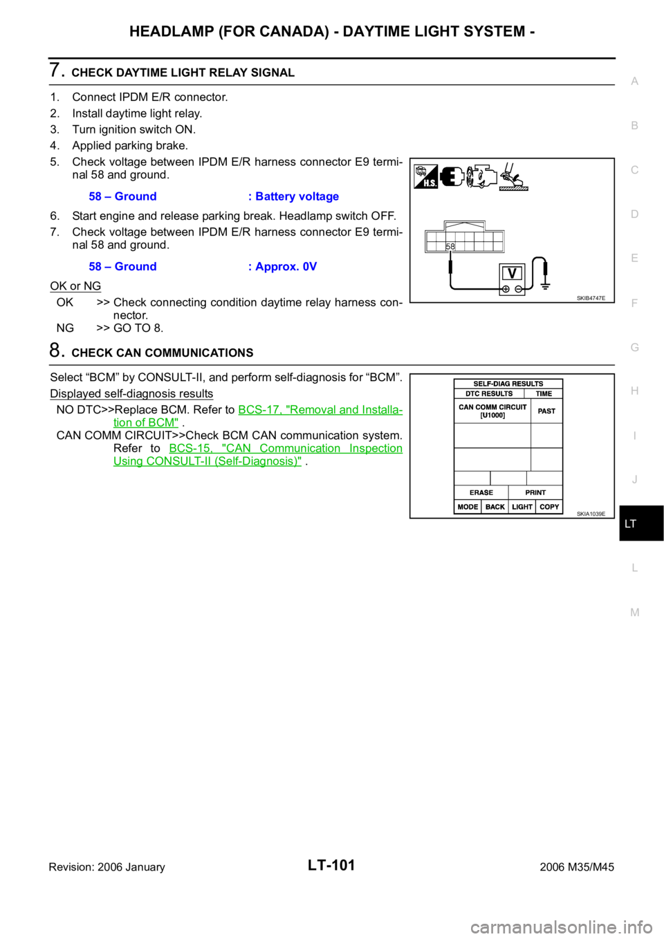
7. CHECK DAYTIME LIGHT RELAY SIGNAL
1. Connect IPDM E/R connector.
2. Install daytime light relay.
3. Turn ignition switch ON.
4. Applied parking brake.
5. Check voltage between IPDM E/R harness connector E9 termi-
nal 58 and ground.
6. Start engine and release parking break. Headlamp switch OFF.
7. Check voltage between IPDM E/R harness connector E9 termi-
nal 58 and ground.
OK or NG
OK >> Check connecting condition daytime relay harness con-
nector.
NG >> GO TO 8.
8. CHECK CAN COMMUNICATIONS
Select “BCM” by CONSULT-II, and perform self-diagnosis for “BCM”.
Displayed self-diagnosis results
NO DTC>>Replace BCM. Refer to BCS-17, "Removal and Installa-
tion of BCM" .
CAN COMM CIRCUIT>>Check BCM CAN communication system.
Refer to BCS-15, "
CAN Communication Inspection
Using CONSULT-II (Self-Diagnosis)" . 58 – Ground : Battery voltage
58 – Ground : Approx. 0V
SKIB4747E
SKIA1039E
Page 4530 of 5621
HEADLAMP (FOR CANADA) - DAYTIME LIGHT SYSTEM -
LT-103
C
D
E
F
G
H
I
J
L
MA
B
LT
Revision: 2006 January2006 M35/M45
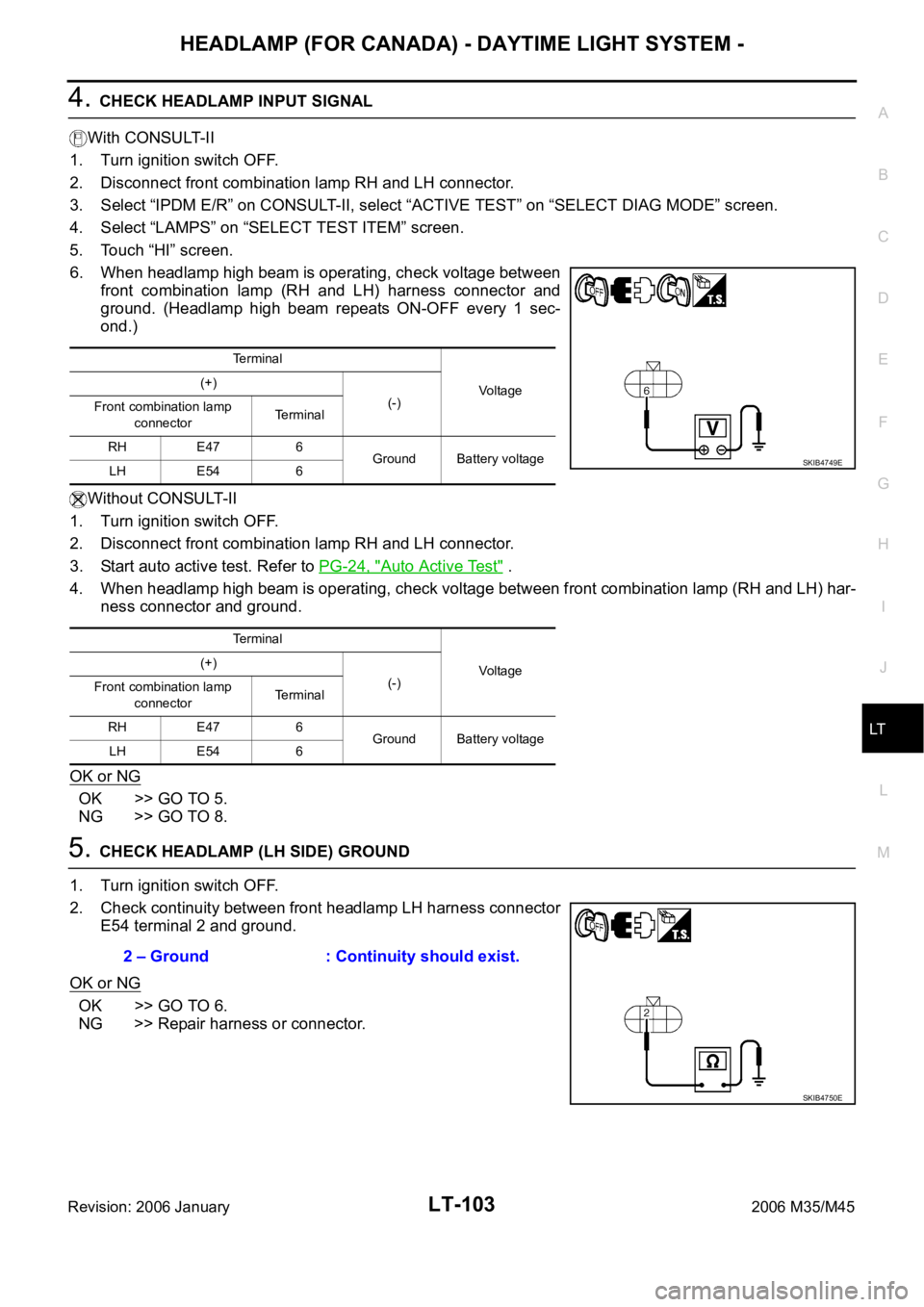
4. CHECK HEADLAMP INPUT SIGNAL
With CONSULT-II
1. Turn ignition switch OFF.
2. Disconnect front combination lamp RH and LH connector.
3. Select “IPDM E/R” on CONSULT-II, select “ACTIVE TEST” on “SELECT DIAG MODE” screen.
4. Select “LAMPS” on “SELECT TEST ITEM” screen.
5. Touch “HI” screen.
6. When headlamp high beam is operating, check voltage between
front combination lamp (RH and LH) harness connector and
ground. (Headlamp high beam repeats ON-OFF every 1 sec-
ond.)
Without CONSULT-II
1. Turn ignition switch OFF.
2. Disconnect front combination lamp RH and LH connector.
3. Start auto active test. Refer to PG-24, "
Auto Active Test" .
4. When headlamp high beam is operating, check voltage between front combination lamp (RH and LH) har-
ness connector and ground.
OK or NG
OK >> GO TO 5.
NG >> GO TO 8.
5. CHECK HEADLAMP (LH SIDE) GROUND
1. Turn ignition switch OFF.
2. Check continuity between front headlamp LH harness connector
E54 terminal 2 and ground.
OK or NG
OK >> GO TO 6.
NG >> Repair harness or connector.
Terminal
Vo l ta g e (+)
(-)
Front combination lamp
connectorTerminal
RH E47 6
Ground Battery voltage
LH E54 6
Terminal
Vo l ta g e (+)
(-)
Front combination lamp
connectorTerminal
RH E47 6
Ground Battery voltage
LH E54 6
SKIB4749E
2 – Ground : Continuity should exist.
SKIB4750E
Page 4532 of 5621
HEADLAMP (FOR CANADA) - DAYTIME LIGHT SYSTEM -
LT-105
C
D
E
F
G
H
I
J
L
MA
B
LT
Revision: 2006 January2006 M35/M45
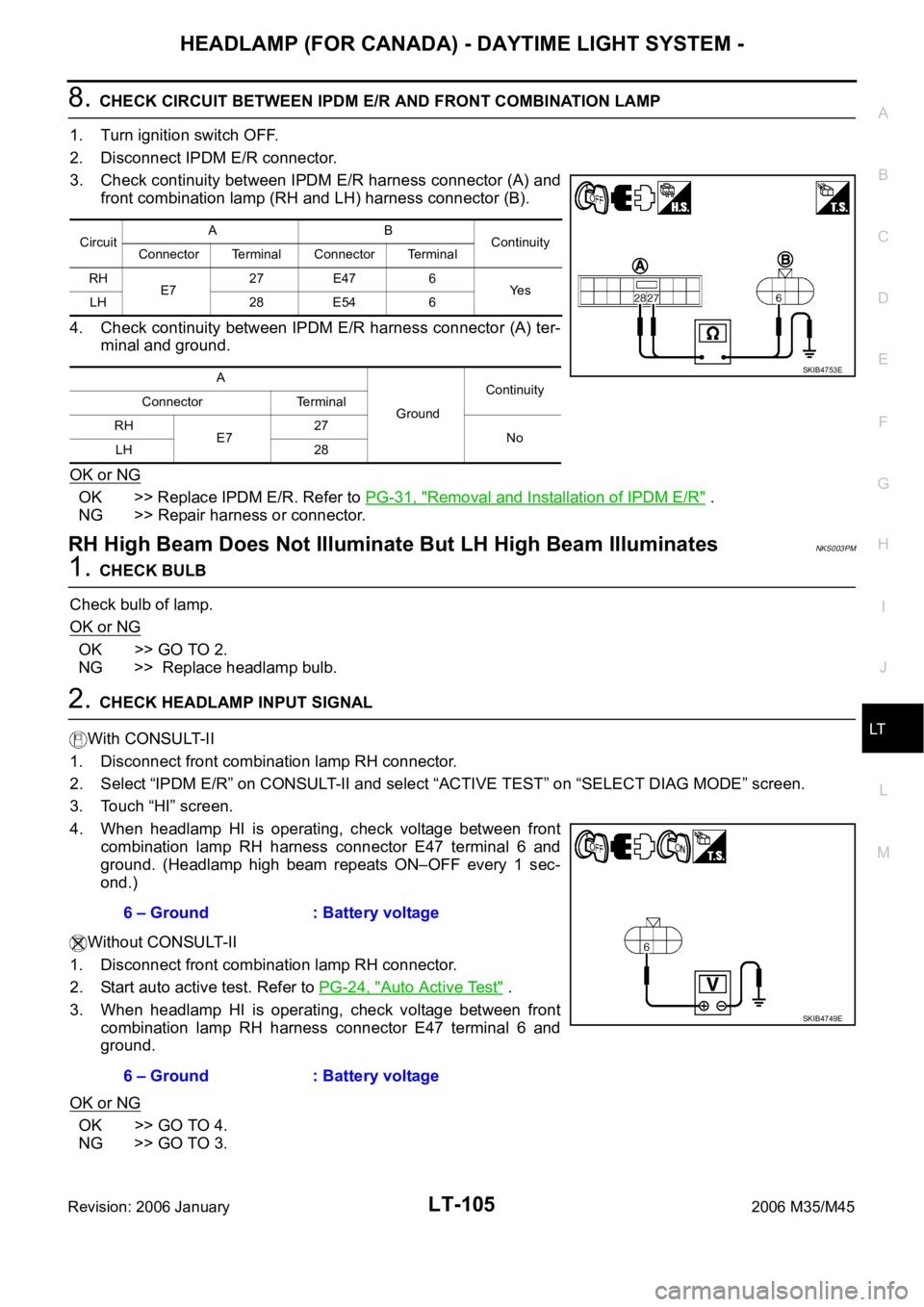
8. CHECK CIRCUIT BETWEEN IPDM E/R AND FRONT COMBINATION LAMP
1. Turn ignition switch OFF.
2. Disconnect IPDM E/R connector.
3. Check continuity between IPDM E/R harness connector (A) and
front combination lamp (RH and LH) harness connector (B).
4. Check continuity between IPDM E/R harness connector (A) ter-
minal and ground.
OK or NG
OK >> Replace IPDM E/R. Refer to PG-31, "Removal and Installation of IPDM E/R" .
NG >> Repair harness or connector.
RH High Beam Does Not Illuminate But LH High Beam IlluminatesNKS003PM
1. CHECK BULB
Check bulb of lamp.
OK or NG
OK >> GO TO 2.
NG >> Replace headlamp bulb.
2. CHECK HEADLAMP INPUT SIGNAL
With CONSULT-II
1. Disconnect front combination lamp RH connector.
2. Select “IPDM E/R” on CONSULT-II and select “ACTIVE TEST” on “SELECT DIAG MODE” screen.
3. Touch “HI” screen.
4. When headlamp HI is operating, check voltage between front
combination lamp RH harness connector E47 terminal 6 and
ground. (Headlamp high beam repeats ON–OFF every 1 sec-
ond.)
Without CONSULT-II
1. Disconnect front combination lamp RH connector.
2. Start auto active test. Refer to PG-24, "
Auto Active Test" .
3. When headlamp HI is operating, check voltage between front
combination lamp RH harness connector E47 terminal 6 and
ground.
OK or NG
OK >> GO TO 4.
NG >> GO TO 3.
CircuitAB
Continuity
Connector Terminal Connector Terminal
RH
E727 E47 6
Ye s
LH 28 E54 6
A
GroundContinuity
Connector Terminal
RH
E727
No
LH 28
SKIB4753E
6 – Ground : Battery voltage
6 – Ground : Battery voltage
SKIB4749E
Page 4533 of 5621
LT-106
HEADLAMP (FOR CANADA) - DAYTIME LIGHT SYSTEM -
Revision: 2006 January2006 M35/M45
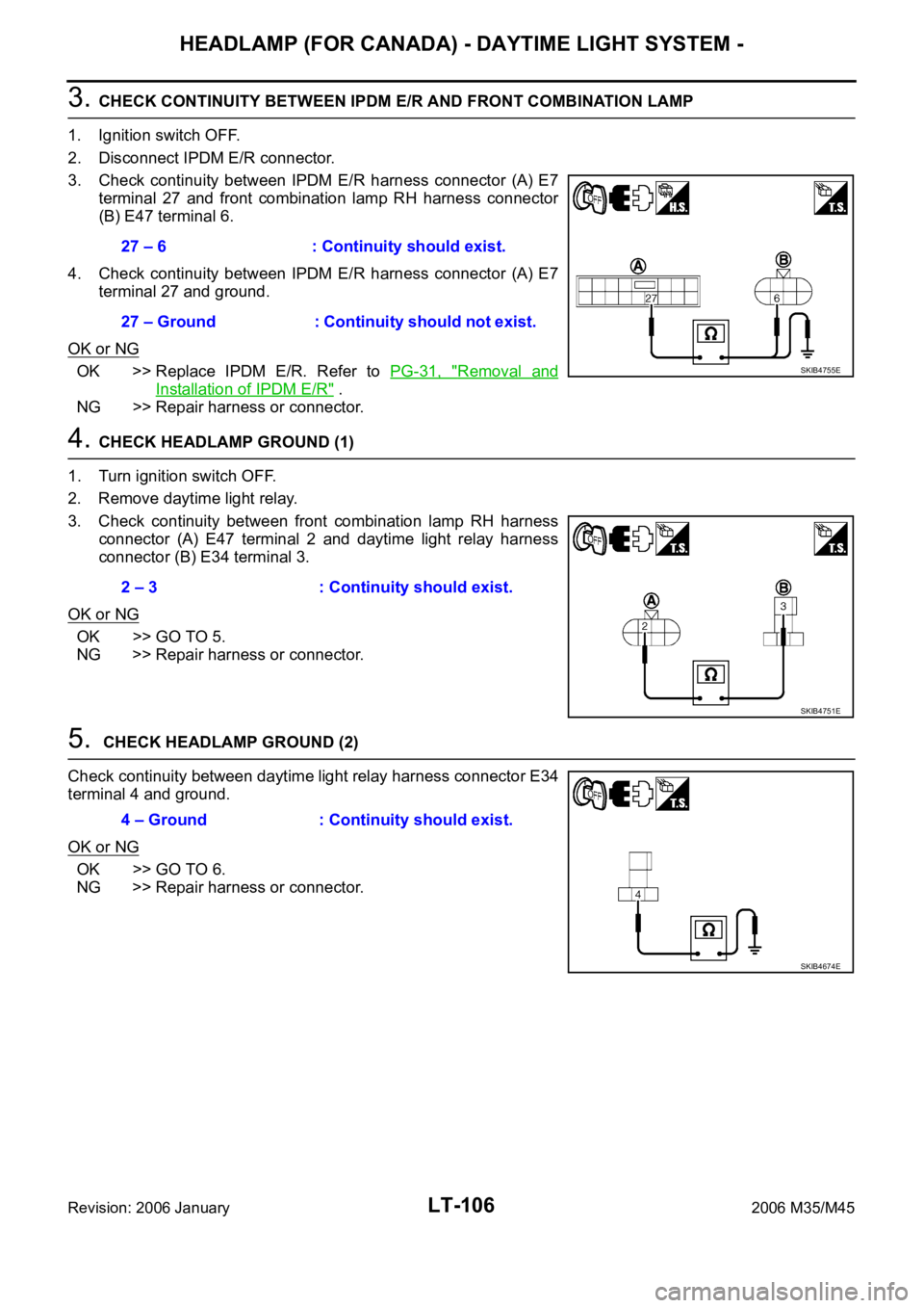
3. CHECK CONTINUITY BETWEEN IPDM E/R AND FRONT COMBINATION LAMP
1. Ignition switch OFF.
2. Disconnect IPDM E/R connector.
3. Check continuity between IPDM E/R harness connector (A) E7
terminal 27 and front combination lamp RH harness connector
(B) E47 terminal 6.
4. Check continuity between IPDM E/R harness connector (A) E7
terminal 27 and ground.
OK or NG
OK >> Replace IPDM E/R. Refer to PG-31, "Removal and
Installation of IPDM E/R" .
NG >> Repair harness or connector.
4. CHECK HEADLAMP GROUND (1)
1. Turn ignition switch OFF.
2. Remove daytime light relay.
3. Check continuity between front combination lamp RH harness
connector (A) E47 terminal 2 and daytime light relay harness
connector (B) E34 terminal 3.
OK or NG
OK >> GO TO 5.
NG >> Repair harness or connector.
5. CHECK HEADLAMP GROUND (2)
Check continuity between daytime light relay harness connector E34
terminal 4 and ground.
OK or NG
OK >> GO TO 6.
NG >> Repair harness or connector.27 – 6 : Continuity should exist.
27 – Ground : Continuity should not exist.
SKIB4755E
2 – 3 : Continuity should exist.
SKIB4751E
4 – Ground : Continuity should exist.
SKIB4674E
Page 4535 of 5621
LT-108
HEADLAMP (FOR CANADA) - DAYTIME LIGHT SYSTEM -
Revision: 2006 January2006 M35/M45
3. CHECK HEADLAMP GROUND
1. Turn ignition switch OFF.
2. Check continuity headlamp harness connector E54 terminal 2
and ground.
OK or NG
OK >> Check connecting condition front headlamp LH connec-
tor harness.
NG >> Repair harness or connector.
4. CHECK CIRCUIT BETWEEN IPDM E/R AND FRONT COMBINATION LAMP
1. Turn ignition switch OFF.
2. Disconnect IPDM E/R connector and front combination lamp LH connector.
3. Check continuity between IPDM E/R harness connector (A) E7
terminal 28 and front combination lamp LH harness connector
(B) E54 terminal 6.
4. Check continuity between IPDM E/R harness connector (A) E7
terminal 28 and ground.
OK or NG
OK >> Replace IPDM E/R. Refer to PG-31, "Removal and
Installation of IPDM E/R" .
NG >> Repair harness or connector.2 – Ground : Continuity should exist.
SKIB4750E
28 – 6 : Continuity should exist.
28 – Ground : Continuity should not exist.
SKIB4757E
Page 4537 of 5621
LT-110
HEADLAMP (FOR CANADA) - DAYTIME LIGHT SYSTEM -
Revision: 2006 January2006 M35/M45
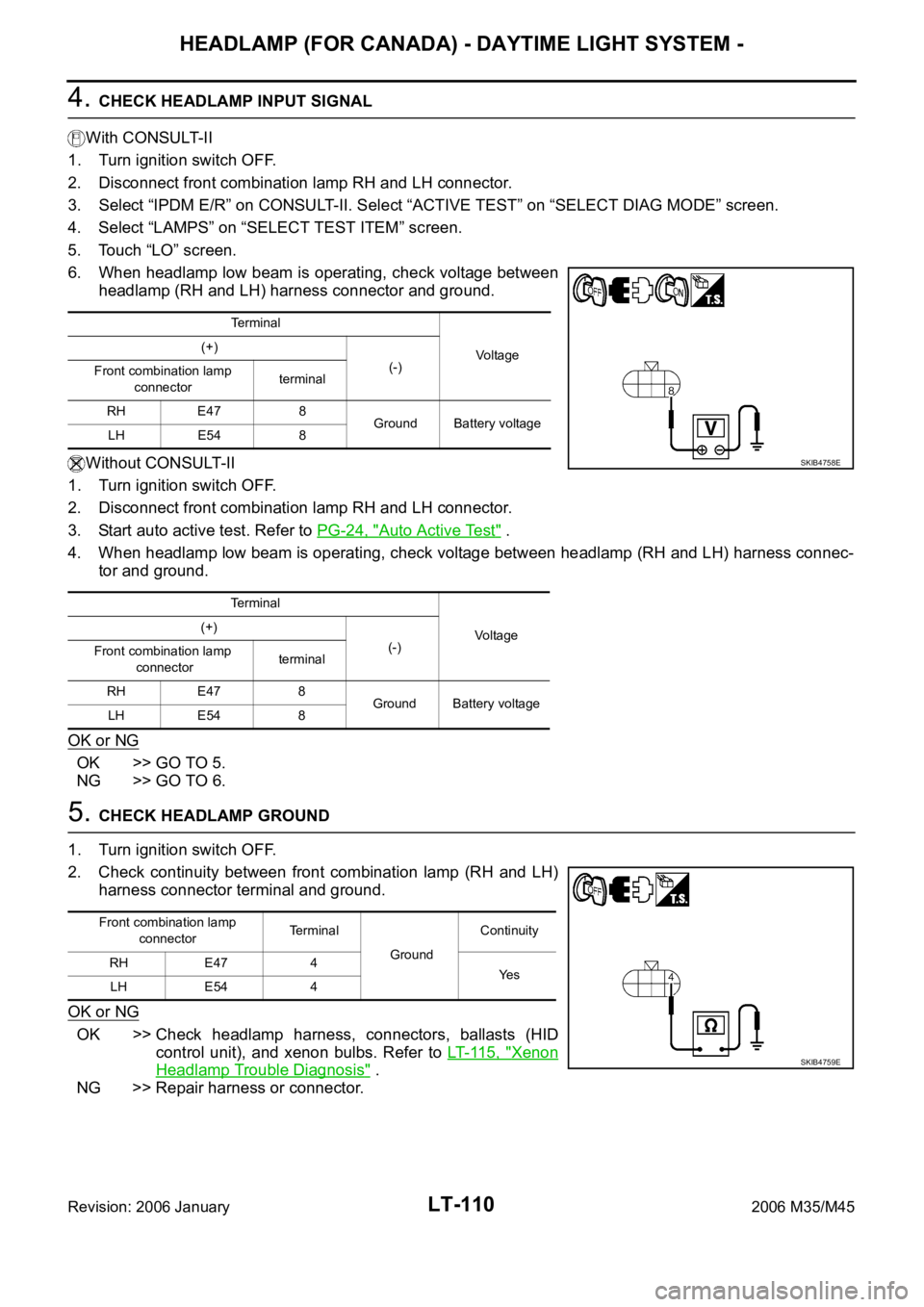
4. CHECK HEADLAMP INPUT SIGNAL
With CONSULT-II
1. Turn ignition switch OFF.
2. Disconnect front combination lamp RH and LH connector.
3. Select “IPDM E/R” on CONSULT-II. Select “ACTIVE TEST” on “SELECT DIAG MODE” screen.
4. Select “LAMPS” on “SELECT TEST ITEM” screen.
5. Touch “LO” screen.
6. When headlamp low beam is operating, check voltage between
headlamp (RH and LH) harness connector and ground.
Without CONSULT-II
1. Turn ignition switch OFF.
2. Disconnect front combination lamp RH and LH connector.
3. Start auto active test. Refer to PG-24, "
Auto Active Test" .
4. When headlamp low beam is operating, check voltage between headlamp (RH and LH) harness connec-
tor and ground.
OK or NG
OK >> GO TO 5.
NG >> GO TO 6.
5. CHECK HEADLAMP GROUND
1. Turn ignition switch OFF.
2. Check continuity between front combination lamp (RH and LH)
harness connector terminal and ground.
OK or NG
OK >> Check headlamp harness, connectors, ballasts (HID
control unit), and xenon bulbs. Refer to LT- 11 5 , "
Xenon
Headlamp Trouble Diagnosis" .
NG >> Repair harness or connector.
Terminal
Vo l ta g e (+)
(-)
Front combination lamp
connectorterminal
RH E47 8
Ground Battery voltage
LH E54 8
Terminal
Voltage (+)
(-)
Front combination lamp
connectorterminal
RH E47 8
Ground Battery voltage
LH E54 8
SKIB4758E
Front combination lamp
connectorTerminal
GroundContinuity
RH E47 4
Ye s
LH E54 4
SKIB4759E
Page 4538 of 5621
HEADLAMP (FOR CANADA) - DAYTIME LIGHT SYSTEM -
LT-111
C
D
E
F
G
H
I
J
L
MA
B
LT
Revision: 2006 January2006 M35/M45
6. CHECK CIRCUIT BETWEEN IPDM E/R AND FRONT COMBINATION LAMP
1. Turn ignition switch OFF.
2. Disconnect IPDM E/R connector.
3. Check continuity between IPDM E/R harness connector (A) ter-
minal and front combination lamp (RH and LH) harness connec-
tor (B) terminal.
4. Check continuity between IPDM E/R harness connector (A) ter-
minal and ground.
OK or NG
OK >> Replace IPDM E/R. Refer to PG-31, "Removal and Installation of IPDM E/R" .
NG >> Repair harness or connector.
CircuitAB
Continuity
Connector Terminal Connector Terminal
RH
E720 E47 8
Ye s
LH 30 E54 8
A
GroundContinuity
Connector Terminal
RH
E720
No
LH 30
SKIB4760E
Page 4539 of 5621
LT-112
HEADLAMP (FOR CANADA) - DAYTIME LIGHT SYSTEM -
Revision: 2006 January2006 M35/M45
Headlamp Low Beam Does Not Illuminate (One Side)NKS003PP
1. CHECK BULB
Check ballast (HID control unit) and xenon bulb of lamp which does not illuminate. Refer to LT- 11 5 , "
Xenon
Headlamp Trouble Diagnosis" .
OK or NG
OK >> GO TO 2.
NG >> Repair malfunctioning part.
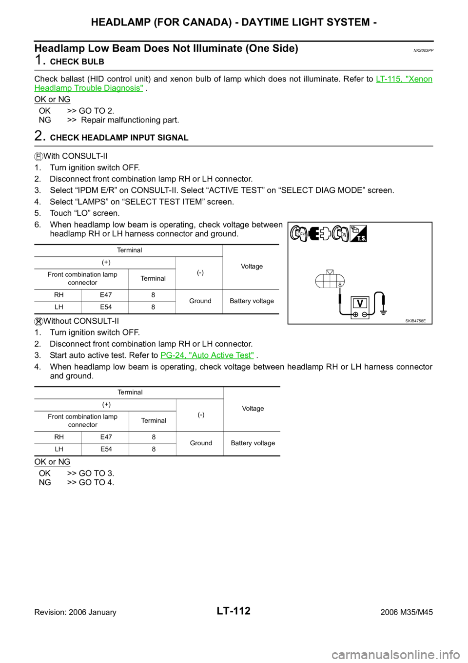
2. CHECK HEADLAMP INPUT SIGNAL
With CONSULT-II
1. Turn ignition switch OFF.
2. Disconnect front combination lamp RH or LH connector.
3. Select “IPDM E/R” on CONSULT-II. Select “ACTIVE TEST” on “SELECT DIAG MODE” screen.
4. Select “LAMPS” on “SELECT TEST ITEM” screen.
5. Touch “LO” screen.
6. When headlamp low beam is operating, check voltage between
headlamp RH or LH harness connector and ground.
Without CONSULT-II
1. Turn ignition switch OFF.
2. Disconnect front combination lamp RH or LH connector.
3. Start auto active test. Refer to PG-24, "
Auto Active Test" .
4. When headlamp low beam is operating, check voltage between headlamp RH or LH harness connector
and ground.
OK or NG
OK >> GO TO 3.
NG >> GO TO 4.
Terminal
Vo l ta g e (+)
(-)
Front combination lamp
connectorTerminal
RH E47 8
Ground Battery voltage
LH E54 8
Terminal
Voltage (+)
(-)
Front combination lamp
connectorTerminal
RH E47 8
Ground Battery voltage
LH E54 8
SKIB4758E