Page 4463 of 5621

LT-36
HEADLAMP (FOR USA) - CONVENTIONAL TYPE -
Revision: 2006 January2006 M35/M45
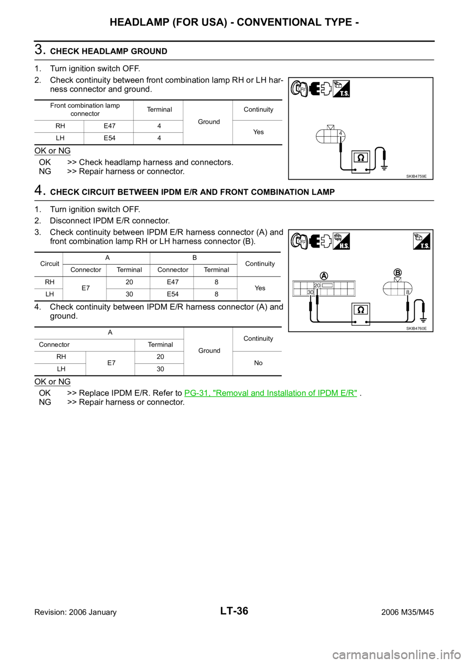
3. CHECK HEADLAMP GROUND
1. Turn ignition switch OFF.
2. Check continuity between front combination lamp RH or LH har-
ness connector and ground.
OK or NG
OK >> Check headlamp harness and connectors.
NG >> Repair harness or connector.
4. CHECK CIRCUIT BETWEEN IPDM E/R AND FRONT COMBINATION LAMP
1. Turn ignition switch OFF.
2. Disconnect IPDM E/R connector.
3. Check continuity between IPDM E/R harness connector (A) and
front combination lamp RH or LH harness connector (B).
4. Check continuity between IPDM E/R harness connector (A) and
ground.
OK or NG
OK >> Replace IPDM E/R. Refer to PG-31, "Removal and Installation of IPDM E/R" .
NG >> Repair harness or connector.
Front combination lamp
connectorTerminal
GroundContinuity
RH E47 4
Ye s
LH E54 4
SKIB4759E
CircuitAB
Continuity
Connector Terminal Connector Terminal
RH
E720 E47 8
Ye s
LH 30 E54 8
A
GroundContinuity
Connector Terminal
RH
E720
No
LH 30
SKIB4760E
Page 4464 of 5621

HEADLAMP (FOR USA) - CONVENTIONAL TYPE -
LT-37
C
D
E
F
G
H
I
J
L
MA
B
LT
Revision: 2006 January2006 M35/M45
Headlamps Do Not Turn OFFNKS003OF
1. CHECK HEADLAMP TURN OFF
Make sure that lighting switch is OFF. And make sure headlamp turns off when ignition switch is turned OFF.
OK or NG
OK >> GO TO 3.
NG >> GO TO 2.
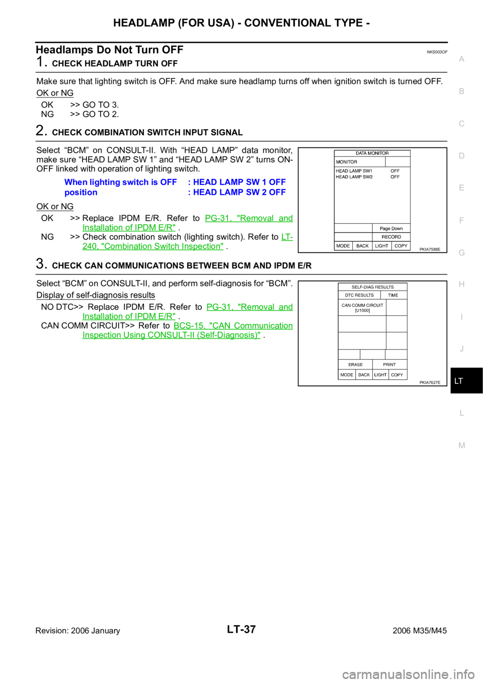
2. CHECK COMBINATION SWITCH INPUT SIGNAL
Select “BCM” on CONSULT-II. With “HEAD LAMP” data monitor,
make sure “HEAD LAMP SW 1” and “HEAD LAMP SW 2” turns ON-
OFF linked with operation of lighting switch.
OK or NG
OK >> Replace IPDM E/R. Refer to PG-31, "Removal and
Installation of IPDM E/R" .
NG >> Check combination switch (lighting switch). Refer to LT-
240, "Combination Switch Inspection" .
3. CHECK CAN COMMUNICATIONS BETWEEN BCM AND IPDM E/R
Select “BCM” on CONSULT-II, and perform self-diagnosis for “BCM”.
Display of self-diagnosis results
NO DTC>> Replace IPDM E/R. Refer to PG-31, "Removal and
Installation of IPDM E/R" .
CAN COMM CIRCUIT>> Refer to BCS-15, "
CAN Communication
Inspection Using CONSULT-II (Self-Diagnosis)" . When lighting switch is OFF
position: HEAD LAMP SW 1 OFF
: HEAD LAMP SW 2 OFF
PKIA7588E
PKIA7627E
Page 4471 of 5621

LT-44
HEADLAMP (FOR USA) - XENON TYPE -
Revision: 2006 January2006 M35/M45
OUTLINE
Power is supplied at all times
to headlamp high relay, located in IPDM E/R and
to headlamp low relay, located in IPDM E/R, from battery direct,
through 15A fuse (No. 71, located in IPDM E/R)
to CPU, located in IPDM E/R,
through 15A fuse (No. 78, located in IPDM E/R)
to CPU, located in IPDM E/R,
through 50A fusible link (letter F, located in fuse and fusible link block)
to BCM terminal 55,
through 10A fuse [No. 21, located in fuse block (J/B)]
to BCM terminal 42 and
to combination meter terminal 23,
through 10A fuse [No. 19, located in fuse block (J/B)]
to unified meter and A/C amp. terminal 54,
through 10A fuse [No. 22, located in fuse block (J/B)]
to key slot terminal 1.
When the ignition switch is in the ON or START position, power is supplied
to CPU, located in IPDM E/R,
through 15A fuse [No. 1, located in fuse block (J/B)]
to BCM terminal 38,
through 10A fuse [No. 14, located in fuse block (J/B)]
to combination meter terminal 12,
through 10A fuse [No. 12, located in fuse block (J/B)]
to unified meter and A/C amp. terminal 53.
When the ignition switch is in the ACC or ON position, power is supplied
through 10A fuse [No. 6, located in fuse block (J/B)]
to BCM terminal 11.
Ground is supplied
to BCM terminal 52
to combination meter terminals 9, 10, and 11
to unified meter and A/C amp. terminals 55 and 71
to push-button ignition switch (push switch) terminal 1
to key slot terminal 8
through grounds M16 and M70,
to IPDM E/R terminals 38 and 51
through grounds E22 and E43.
Page 4473 of 5621

LT-46
HEADLAMP (FOR USA) - XENON TYPE -
Revision: 2006 January2006 M35/M45
COMBINATION SWITCH READING FUNCTION
Refer to BCS-3, "COMBINATION SWITCH READING FUNCTION" .
EXTERIOR LAMP BATTERY SAVER CONTROL
When the combination switch (lighting switch) is in the 2ND position (ON), and the ignition switch is turned
from ON or ACC to OFF, the battery saver control function is activated.
Under this condition, the headlamps remain illuminated for 5 minutes, then the headlamps are turned off.
Exterior lamp battery saver control mode can be changed by the function setting of CONSULT-II.
AUTO LIGHT OPERATION
Refer to LT-116, "System Description" .
XENON HEADLAMP
Xenon type lamps are used for to the low beam headlamps. Xenon bulbs do not use a filament. Instead, they
produce light when a high voltage current is passed between two tungsten electrodes through a mixture of
xenon (an inert gas) and certain other metal halides. In addition to strong lighting power, electronic control of
the power supply gives the headlamps stable quality and tone color.
Followings are some advantages of the xenon type headlamp.
The light produced by the headlamps is white color similar to sunlight that is easy to the eyes.
Light output is nearly double that of halogen headlamps, affording increased area of illumination.
Counter-reflected luminance increases and the contrast enhances on the wet road in the rain. That makes
visibility go up more than the increase of the light volume.
Power consumption is approximately 25 percent less than halogen headlamps, reducing battery load.
CAN Communication System DescriptionNKS003OM
CAN (Controller Area Network) is a serial communication line for real time application. It is an on-vehicle mul-
tiplex communication line with high data communication speed and excellent error detection ability. Many elec-
tronic control units are equipped onto a vehicle, and each control unit shares information and links with other
control units during operation (not independent). In CAN communication, control units are connected with 2
communication lines (CAN H line, CAN L line) allowing a high rate of information transmission with less wiring.
Each control unit transmits/receives data but selectively reads required data only.
CAN Communication UnitNKS003ON
Refer to LAN-34, "CAN Communication Unit" .
Page 4480 of 5621

HEADLAMP (FOR USA) - XENON TYPE -
LT-53
C
D
E
F
G
H
I
J
L
MA
B
LT
Revision: 2006 January2006 M35/M45
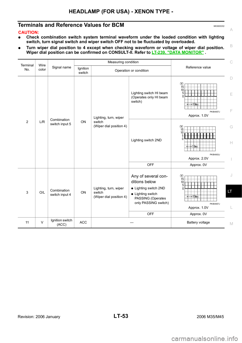
Terminals and Reference Values for BCMNKS003OQ
CAUTION:
Check combination switch system terminal waveform under the loaded condition with lighting
switch, turn signal switch and wiper switch OFF not to be fluctuated by overloaded.
Turn wiper dial position to 4 except when checking waveform or voltage of wiper dial position.
Wiper dial position can be confirmed on CONSULT-II. Refer to LT-239, "
DATA MONITOR" .
Terminal
No.Wire
colorSignal nameMeasuring condition
Reference value
Ignition
switchOperation or condition
2L/RCombination
switch input 5ONLighting, turn, wiper
switch
(Wiper dial position 4)Lighting switch HI beam
(Operates only HI beam
switch)
Approx. 1.0V
Lighting switch 2ND
Approx. 2.0V
OFF Approx. 0V
3O/LCombination
switch input 4ONLighting, turn, wiper
switch
(Wiper dial position 4)
Any of several con-
ditions below
Lighting switch 2ND
Lighting switch
PASSING (Operates
only PASSING switch)
Approx. 1.0V
OFF Approx. 0V
11 VIgnition switch
(ACC)ACC — Battery voltage
PKIB4957J
PKIB4953J
PKIB4957J
Page 4481 of 5621
LT-54
HEADLAMP (FOR USA) - XENON TYPE -
Revision: 2006 January2006 M35/M45
34 LCombination
switch output 3ONLighting, turn, wiper
switch
(Wiper dial position 4)
Any of several con-
ditions below
Lighting switch 2ND
Lighting switch HI
beam (Operates only
HI beam switch)
Approx. 1.2V
OFF
Approx. 7.0 - 7.5V
35 SBCombination
switch output 2ONLighting, turn, wiper
switch
(Wiper dial position 4)
Any of several con-
ditions below
Lighting switch 2ND
Lighting switch
PASSING (Operates
only PASSING switch)
Approx. 1.2V
OFF
Approx. 7.0 - 7.5V
38 WIgnition switch
(ON) ON — Battery voltage
39 L CAN
H — — —
40 P CAN
L — — —
42 PBattery power
supplyOFF — Battery voltage
52 B Ground ON — Approx. 0V
55 WBattery power
supplyOFF — Battery voltage Te r m i n a l
No.Wire
colorSignal nameMeasuring condition
Reference value
Ignition
switchOperation or condition
PKIB4958J
PKIB4960J
PKIB4958J
PKIB4960J
Page 4482 of 5621

HEADLAMP (FOR USA) - XENON TYPE -
LT-55
C
D
E
F
G
H
I
J
L
MA
B
LT
Revision: 2006 January2006 M35/M45
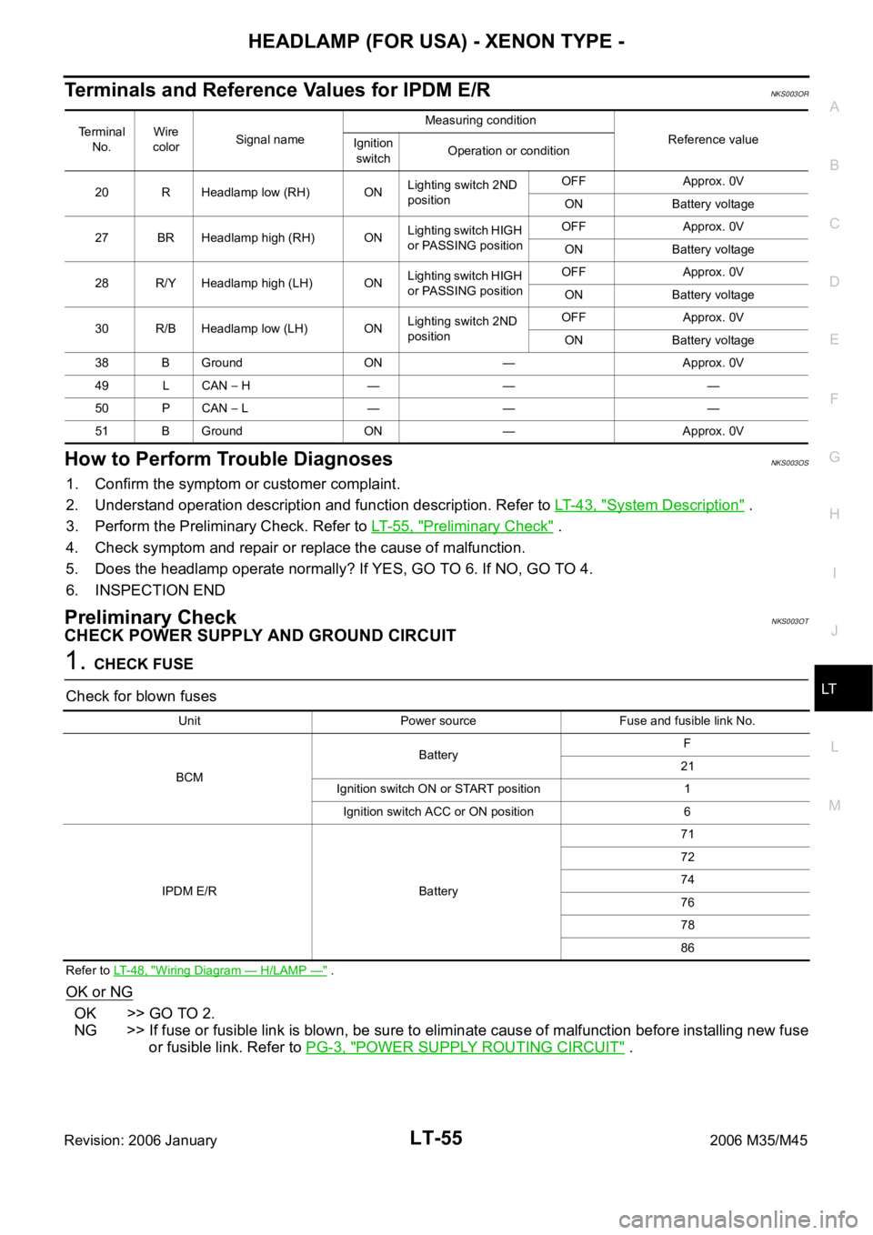
Terminals and Reference Values for IPDM E/RNKS003OR
How to Perform Trouble DiagnosesNKS003OS
1. Confirm the symptom or customer complaint.
2. Understand operation description and function description. Refer to LT- 4 3 , "
System Description" .
3. Perform the Preliminary Check. Refer to LT-55, "
Preliminary Check" .
4. Check symptom and repair or replace the cause of malfunction.
5. Does the headlamp operate normally? If YES, GO TO 6. If NO, GO TO 4.
6. INSPECTION END
Preliminary CheckNKS003OT
CHECK POWER SUPPLY AND GROUND CIRCUIT
1. CHECK FUSE
Check for blown fuses
Refer to LT-48, "Wiring Diagram — H/LAMP —" .
OK or NG
OK >> GO TO 2.
NG >> If fuse or fusible link is blown, be sure to eliminate cause of malfunction before installing new fuse
or fusible link. Refer to PG-3, "
POWER SUPPLY ROUTING CIRCUIT" .
Terminal
No.Wire
colorSignal nameMeasuring condition
Reference value
Ignition
switchOperation or condition
20 R Headlamp low (RH) ONLighting switch 2ND
positionOFF Approx. 0V
ON Battery voltage
27 BR Headlamp high (RH) ONLighting switch HIGH
or PASSING positionOFF Approx. 0V
ON Battery voltage
28 R/Y Headlamp high (LH) ONLighting switch HIGH
or PASSING positionOFF Approx. 0V
ON Battery voltage
30 R/B Headlamp low (LH) ONLighting switch 2ND
positionOFF Approx. 0V
ON Battery voltage
38 B Ground ON — Approx. 0V
49 L CAN
H — — —
50 P CAN
L — — —
51 B Ground ON — Approx. 0V
Unit Power source Fuse and fusible link No.
BCMBatteryF
21
Ignition switch ON or START position 1
Ignition switch ACC or ON position 6
IPDM E/R Battery71
72
74
76
78
86
Page 4483 of 5621
LT-56
HEADLAMP (FOR USA) - XENON TYPE -
Revision: 2006 January2006 M35/M45
2. CHECK POWER SUPPLY CIRCUIT
1. Turn ignition switch OFF.
2. Disconnect BCM connector.
3. Check voltage between BCM harness connector and ground.
OK or NG
OK >> GO TO 3.
NG >> Check harness for open or short between BCM and
fuse.
3. CHECK GROUND CIRCUIT
Check continuity between BCM harness connector and ground.
OK or NG
OK >> INSPECTION END
NG >> Check harness ground circuit.
Terminal Ignition switch position
(+)
(
)OFFACCON
BCM
connectorTerminal
M111
GroundApprox. 0VBattery
voltageBattery
voltage
38 Approx. 0V Approx. 0VBattery
voltage
M242Battery
voltageBattery
voltageBattery
voltage
55Battery
voltageBattery
voltageBattery
voltage
PKIA5204E
BCM connector Terminal
GroundContinuity
M2 52 Yes
SKIB5125E