2006 INFINITI M35 lock
[x] Cancel search: lockPage 1026 of 5621
INTELLIGENT KEY SYSTEM
BL-87
C
D
E
F
G
H
J
K
L
MA
B
BL
Revision: 2006 January2006 M35/M45
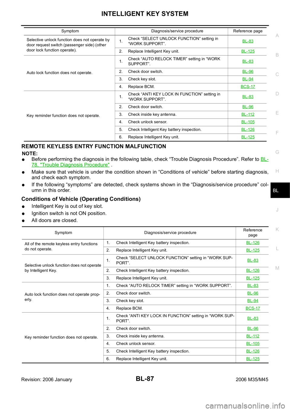
REMOTE KEYLESS ENTRY FUNCTION MALFUNCTION
NOTE:
Before performing the diagnosis in the following table, check “Trouble Diagnosis Procedure”. Refer to BL-
78, "Trouble Diagnosis Procedure" .
Make sure that vehicle is under the condition shown in “Conditions of vehicle” before starting diagnosis,
and check each symptom.
If the following “symptoms” are detected, check systems shown in the “Diagnosis/service procedure” col-
umn in this order.
Conditions of Vehicle (Operating Conditions)
Intelligent Key is out of key slot.
Ignition switch is not ON position.
All doors are closed.
Selective unlock function does not operate by
door request switch (passenger side) (other
door lock function operate).1.Check “SELECT UNLOCK FUNCTION” setting in
“WORK SUPPORT”.BL-83
2. Replace Intelligent Key unit.BL-125
Auto lock function does not operate.1.Check “AUTO RELOCK TIMER” setting in “WORK
SUPPORT”.BL-832. Check door switch.BL-96
3. Check key slot.BL-94
4. Replace BCM.BCS-17
Key reminder function does not operate.1.Check “ANTI KEY LOCK IN FUNCTION” setting in
“WORK SUPPORT”.BL-83
2. Check door switch.BL-96
3. Check inside key antenna.BL-112
4. Check unlock sensor.BL-105
5. Check Intelligent Key battery inspection.BL-126
6. Replace Intelligent Key unit.BL-125
Symptom Diagnosis/service procedure Reference page
Symptom Diagnosis/service procedureReference
page
All of the remote keyless entry functions
do not operate.1. Check Intelligent Key battery inspection.BL-126
2. Replace Intelligent Key unit.BL-125
Selective unlock function does not operate
by Intelligent Key.1.Check “SELECT UNLOCK FUNCTION” setting in “WORK SUP-
PORT”.BL-83
2. Check Intelligent Key battery inspection.BL-126
3. Replace Intelligent Key unit.BL-125
Auto lock function does not operate prop-
erly.1. Check “AUTO RELOCK TIMER” setting in “WORK SUPPORT”.BL-832. Check door switch.BL-96
3. Check key slot.BL-94
4. Replace BCM.BCS-17
Key reminder function does not operate.1.Check “ANTI KEY LOCK IN FUNCTION” setting in “WORK SUP-
PORT”.BL-83
2. Check door switch.BL-96
3. Check inside key antenna.BL-112
4. Check unlock sensor.BL-105
5. Check Intelligent Key battery inspection.BL-126
6. Replace Intelligent Key unit.BL-125
Page 1028 of 5621
INTELLIGENT KEY SYSTEM
BL-89
C
D
E
F
G
H
J
K
L
MA
B
BL
Revision: 2006 January2006 M35/M45
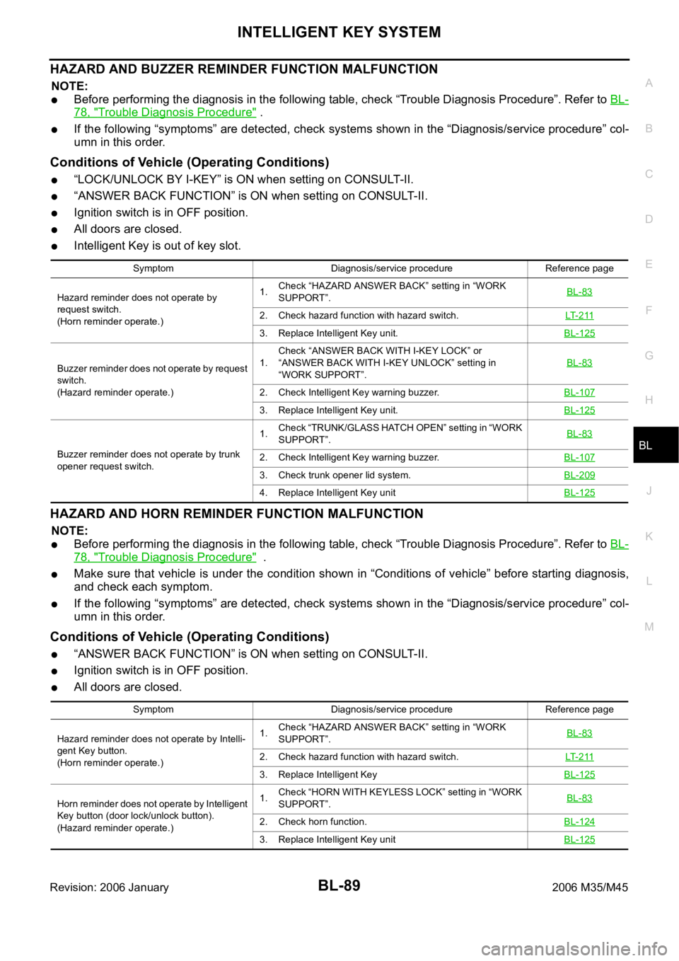
HAZARD AND BUZZER REMINDER FUNCTION MALFUNCTION
NOTE:
Before performing the diagnosis in the following table, check “Trouble Diagnosis Procedure”. Refer to BL-
78, "Trouble Diagnosis Procedure" .
If the following “symptoms” are detected, check systems shown in the “Diagnosis/service procedure” col-
umn in this order.
Conditions of Vehicle (Operating Conditions)
“LOCK/UNLOCK BY I-KEY” is ON when setting on CONSULT-II.
“ANSWER BACK FUNCTION” is ON when setting on CONSULT-II.
Ignition switch is in OFF position.
All doors are closed.
Intelligent Key is out of key slot.
HAZARD AND HORN REMINDER FUNCTION MALFUNCTION
NOTE:
Before performing the diagnosis in the following table, check “Trouble Diagnosis Procedure”. Refer to BL-
78, "Trouble Diagnosis Procedure" .
Make sure that vehicle is under the condition shown in “Conditions of vehicle” before starting diagnosis,
and check each symptom.
If the following “symptoms” are detected, check systems shown in the “Diagnosis/service procedure” col-
umn in this order.
Conditions of Vehicle (Operating Conditions)
“ANSWER BACK FUNCTION” is ON when setting on CONSULT-II.
Ignition switch is in OFF position.
All doors are closed.
Symptom Diagnosis/service procedure Reference page
Hazard reminder does not operate by
request switch.
(Horn reminder operate.)1.Check “HAZARD ANSWER BACK” setting in “WORK
SUPPORT”.BL-83
2. Check hazard function with hazard switch.LT- 2 11
3. Replace Intelligent Key unit.BL-125
Buzzer reminder does not operate by request
switch.
(Hazard reminder operate.)1.Check “ANSWER BACK WITH I-KEY LOCK” or
“ANSWER BACK WITH I-KEY UNLOCK” setting in
“WORK SUPPORT”.BL-83
2. Check Intelligent Key warning buzzer.BL-107
3. Replace Intelligent Key unit.BL-125
Buzzer reminder does not operate by trunk
opener request switch.1.Check “TRUNK/GLASS HATCH OPEN” setting in “WORK
SUPPORT”.BL-832. Check Intelligent Key warning buzzer.BL-107
3. Check trunk opener lid system.BL-209
4. Replace Intelligent Key unitBL-125
Symptom Diagnosis/service procedure Reference page
Hazard reminder does not operate by Intelli-
gent Key button.
(Horn reminder operate.)1.Check “HAZARD ANSWER BACK” setting in “WORK
SUPPORT”.BL-83
2. Check hazard function with hazard switch.LT- 2 11
3. Replace Intelligent KeyBL-125
Horn reminder does not operate by Intelligent
Key button (door lock/unlock button).
(Hazard reminder operate.)1.Check “HORN WITH KEYLESS LOCK” setting in “WORK
SUPPORT”.BL-83
2. Check horn function.BL-124
3. Replace Intelligent Key unitBL-125
Page 1030 of 5621
INTELLIGENT KEY SYSTEM
BL-91
C
D
E
F
G
H
J
K
L
MA
B
BL
Revision: 2006 January2006 M35/M45
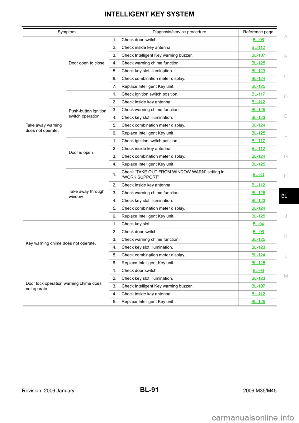
Take away warning
does not operate.Door open to close1. Check door switch.BL-96
2. Check inside key antenna.BL-112
3. Check Intelligent Key warning buzzer.BL-107
4. Check warning chime function.BL-125
5. Check key slot illumination.BL-123
6. Check combination meter display.BL-124
7. Replace Intelligent Key unit. BL-125
Push-button ignition
switch operation1. Check ignition switch position.BL-117
2. Check inside key antenna.BL-112
3. Check warning chime function.BL-125
4. Check key slot illumination.BL-123
5. Check combination meter display.BL-124
6. Replace Intelligent Key unit. BL-125
Door is open1. Check ignition switch position.BL-1172. Check inside key antenna.BL-112
3. Check combination meter display.BL-124
4. Replace Intelligent Key unit. BL-125
Take away through
window1.Check “TAKE OUT FROM WINDOW WARN” setting in
“WORK SUPPORT”.BL-83
2. Check inside key antenna.BL-112
3. Check warning chime function.BL-125
4. Check key slot illumination.BL-123
5. Check combination meter display.BL-124
6. Replace Intelligent Key unit. BL-125
Key warning chime does not operate.1. Check key slot.BL-94
2. Check door switch.BL-96
3. Check warning chime function.BL-125
4. Check key slot illumination.BL-123
5. Check combination meter display.BL-124
6. Replace Intelligent Key unit. BL-125
Door lock operation warning chime does
not operate.1. Check door switch.BL-96
2. Check key slot illumination.BL-123
3. Check Intelligent Key warning buzzer.BL-107
4. Check inside key antenna.BL-112
5. Replace Intelligent Key unit. BL-125
Symptom Diagnosis/service procedure Reference page
Page 1038 of 5621
INTELLIGENT KEY SYSTEM
BL-99
C
D
E
F
G
H
J
K
L
MA
B
BL
Revision: 2006 January2006 M35/M45
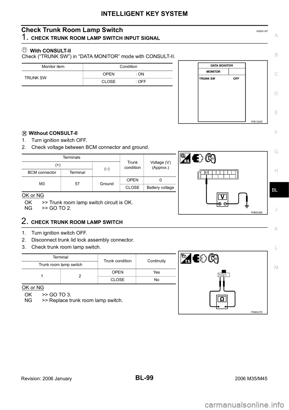
Check Trunk Room Lamp SwitchNIS001XP
1. CHECK TRUNK ROOM LAMP SWITCH INPUT SIGNAL
With CONSULT-II
Check (“TRUNK SW”) in “DATA MONITOR” mode with CONSULT-II.
Without CONSULT-II
1. Turn ignition switch OFF.
2. Check voltage between BCM connector and ground.
OK or NG
OK >> Trunk room lamp switch circuit is OK.
NG >> GO TO 2.
2. CHECK TRUNK ROOM LAMP SWITCH
1. Turn ignition switch OFF.
2. Disconnect trunk lid lock assembly connector.
3. Check trunk room lamp switch.
OK or NG
OK >> GO TO 3.
NG >> Replace trunk room lamp switch.
Monitor item Condition
TRUNK SWOPEN : ON
CLOSE : OFF
PIIB1362E
Terminals
Trunk
conditionVoltage (V)
(Approx.) (+)
(–)
BCM connector Terminal
M3 57 GroundOPEN 0
CLOSE Battery voltage
PIIB6326E
Terminal
Trunk condition Continuity
Trunk room lamp switch
12OPEN Yes
CLOSE No
PIIB6327E
Page 1039 of 5621
BL-100
INTELLIGENT KEY SYSTEM
Revision: 2006 January2006 M35/M45
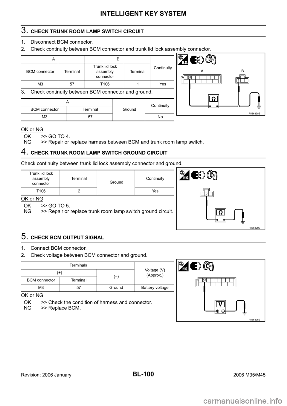
3. CHECK TRUNK ROOM LAMP SWITCH CIRCUIT
1. Disconnect BCM connector.
2. Check continuity between BCM connector and trunk lid lock assembly connector.
3. Check continuity between BCM connector and ground.
OK or NG
OK >> GO TO 4.
NG >> Repair or replace harness between BCM and trunk room lamp switch.
4. CHECK TRUNK ROOM LAMP SWITCH GROUND CIRCUIT
Check continuity between trunk lid lock assembly connector and ground.
OK or NG
OK >> GO TO 5.
NG >> Repair or replace trunk room lamp switch ground circuit.
5. CHECK BCM OUTPUT SIGNAL
1. Connect BCM connector.
2. Check voltage between BCM connector and ground.
OK or NG
OK >> Check the condition of harness and connector.
NG >> Replace BCM.
AB
Continuity
BCM connector TerminalTrunk lid lock
assembly
connectorTerminal
M3 57 T106 1 Yes
A
GroundContinuity
BCM connector Terminal
M3 57 No
PIIB6328E
Trunk lid lock
assembly
connectorTerminal
GroundContinuity
T106 2 Yes
PIIB6329E
Terminals
Voltage (V)
(Approx.) (+)
(–)
BCM connector Terminal
M3 57 Ground Battery voltage
PIIB6326E
Page 1044 of 5621
INTELLIGENT KEY SYSTEM
BL-105
C
D
E
F
G
H
J
K
L
MA
B
BL
Revision: 2006 January2006 M35/M45
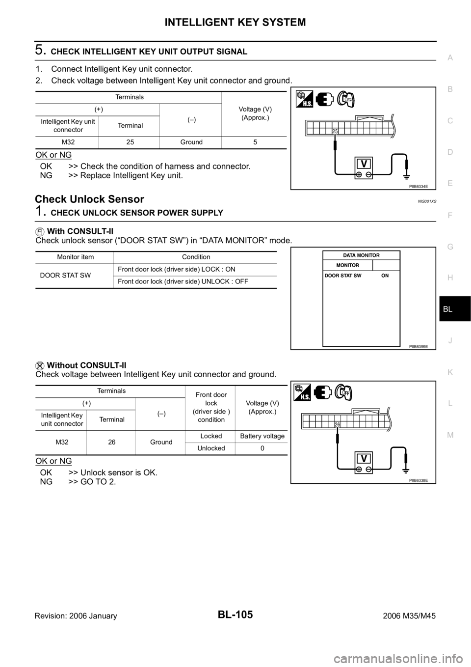
5. CHECK INTELLIGENT KEY UNIT OUTPUT SIGNAL
1. Connect Intelligent Key unit connector.
2. Check voltage between Intelligent Key unit connector and ground.
OK or NG
OK >> Check the condition of harness and connector.
NG >> Replace Intelligent Key unit.
Check Unlock SensorNIS001XS
1. CHECK UNLOCK SENSOR POWER SUPPLY
With CONSULT-II
Check unlock sensor (“DOOR STAT SW”) in “DATA MONITOR” mode.
Without CONSULT-II
Check voltage between Intelligent Key unit connector and ground.
OK or NG
OK >> Unlock sensor is OK.
NG >> GO TO 2.
Terminals
Voltage (V)
(Approx.) (+)
(–)
Intelligent Key unit
connectorTerminal
M32 25 Ground 5
PIIB6334E
Monitor item Condition
DOOR STAT SWFront door lock (driver side) LOCK : ON
Front door lock (driver side) UNLOCK : OFF
PIIB6399E
Terminals
Front door
lock
(driver side )
conditionVoltage (V)
(Approx.) (+)
(–)
Intelligent Key
unit connectorTerminal
M32 26 GroundLocked Battery voltage
Unlocked 0
PIIB6338E
Page 1045 of 5621
BL-106
INTELLIGENT KEY SYSTEM
Revision: 2006 January2006 M35/M45
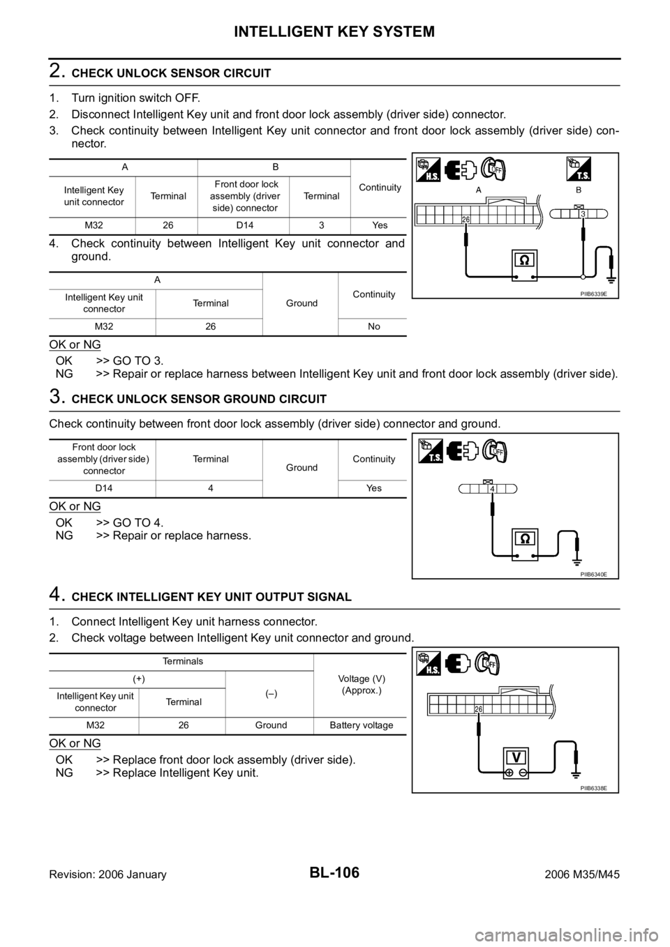
2. CHECK UNLOCK SENSOR CIRCUIT
1. Turn ignition switch OFF.
2. Disconnect Intelligent Key unit and front door lock assembly (driver side) connector.
3. Check continuity between Intelligent Key unit connector and front door lock assembly (driver side) con-
nector.
4. Check continuity between Intelligent Key unit connector and
ground.
OK or NG
OK >> GO TO 3.
NG >> Repair or replace harness between Intelligent Key unit and front door lock assembly (driver side).
3. CHECK UNLOCK SENSOR GROUND CIRCUIT
Check continuity between front door lock assembly (driver side) connector and ground.
OK or NG
OK >> GO TO 4.
NG >> Repair or replace harness.
4. CHECK INTELLIGENT KEY UNIT OUTPUT SIGNAL
1. Connect Intelligent Key unit harness connector.
2. Check voltage between Intelligent Key unit connector and ground.
OK or NG
OK >> Replace front door lock assembly (driver side).
NG >> Replace Intelligent Key unit.
AB
Continuity
Intelligent Key
unit connectorTe r m i n a l Front door lock
assembly (driver
side) connectorTerminal
M32 26 D14 3 Yes
A
GroundContinuity
Intelligent Key unit
connectorTerminal
M32 26 No
PIIB6339E
Front door lock
assembly (driver side)
connectorTerminal
GroundContinuity
D14 4 Yes
PIIB6340E
Terminals
Voltage (V)
(Approx.) (+)
(–)
Intelligent Key unit
connectorTerminal
M32 26 Ground Battery voltage
PIIB6338E
Page 1054 of 5621
INTELLIGENT KEY SYSTEM
BL-115
C
D
E
F
G
H
J
K
L
MA
B
BL
Revision: 2006 January2006 M35/M45
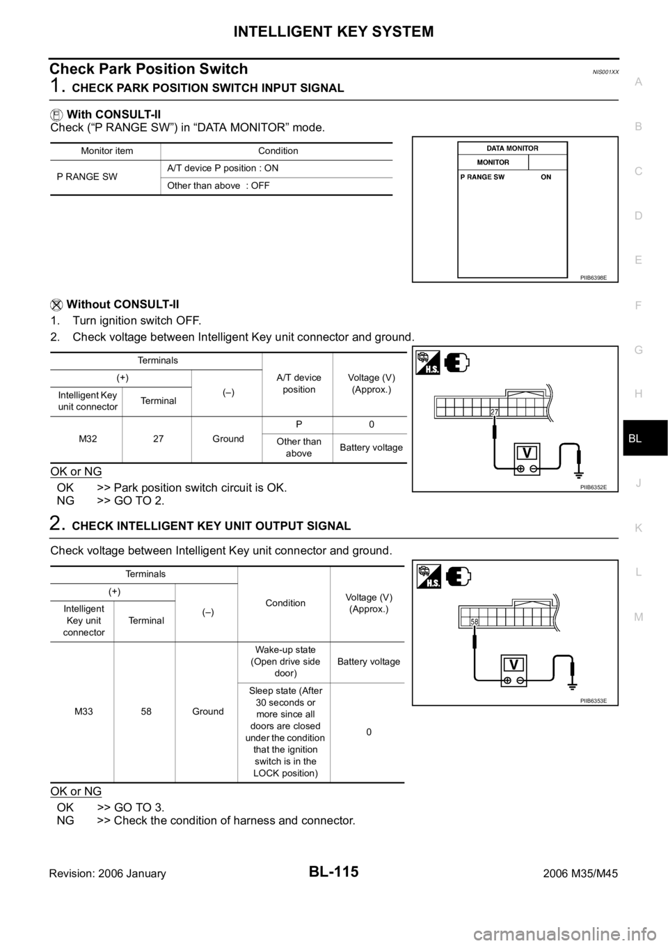
Check Park Position SwitchNIS001XX
1. CHECK PARK POSITION SWITCH INPUT SIGNAL
With CONSULT-II
Check (“P RANGE SW”) in “DATA MONITOR” mode.
Without CONSULT-II
1. Turn ignition switch OFF.
2. Check voltage between Intelligent Key unit connector and ground.
OK or NG
OK >> Park position switch circuit is OK.
NG >> GO TO 2.
2. CHECK INTELLIGENT KEY UNIT OUTPUT SIGNAL
Check voltage between Intelligent Key unit connector and ground.
OK or NG
OK >> GO TO 3.
NG >> Check the condition of harness and connector.
Monitor item Condition
P RANGE SWA/T device P position : ON
Other than above : OFF
PIIB6398E
Te r m i n a l s
A/T device
positionVoltage (V)
(Approx.) (+)
(–)
Intelligent Key
unit connectorTerminal
M32 27 GroundP0
Other than
aboveBattery voltage
PIIB6352E
Terminals
ConditionVoltage (V)
(Approx.) (+)
(–) Intelligent
Key unit
connectorTerminal
M33 58 GroundWake-up state
(Open drive side
door)Battery voltage
Sleep state (After
30 seconds or
more since all
doors are closed
under the condition
that the ignition
switch is in the
LOCK position)0
PIIB6353E