2006 INFINITI M35 steering wheel adjustment
[x] Cancel search: steering wheel adjustmentPage 3366 of 5621
FRONT WHEEL HUB AND KNUCKLE
FAX-7
C
E
F
G
H
I
J
K
L
MA
B
FA X
Revision: 2006 January2006 M35/M45
INSTALLATION
Installation is the reverse order of the removal. For tightening torque, refer to FAX-5, "COMPONENT" .
Perform the final tightening of each of parts under unladen conditions, which were removed when remov-
ing wheel hub and bearing assembly and steering knuckle. Check the wheel alignment. Refer to FSU-6,
"Wheel Alignment Inspection" (2WD), FSU-23, "Wheel Alignment Inspection" (AWD).
Adjust neutral position of steering angle sensor after checking the wheel alignment. Refer to BRC-6,
"Adjustment of Steering Angle Sensor Neutral Position" .
Check wheel sensor harness for proper connection. Refer to BRC-57, "WHEEL SENSOR" .
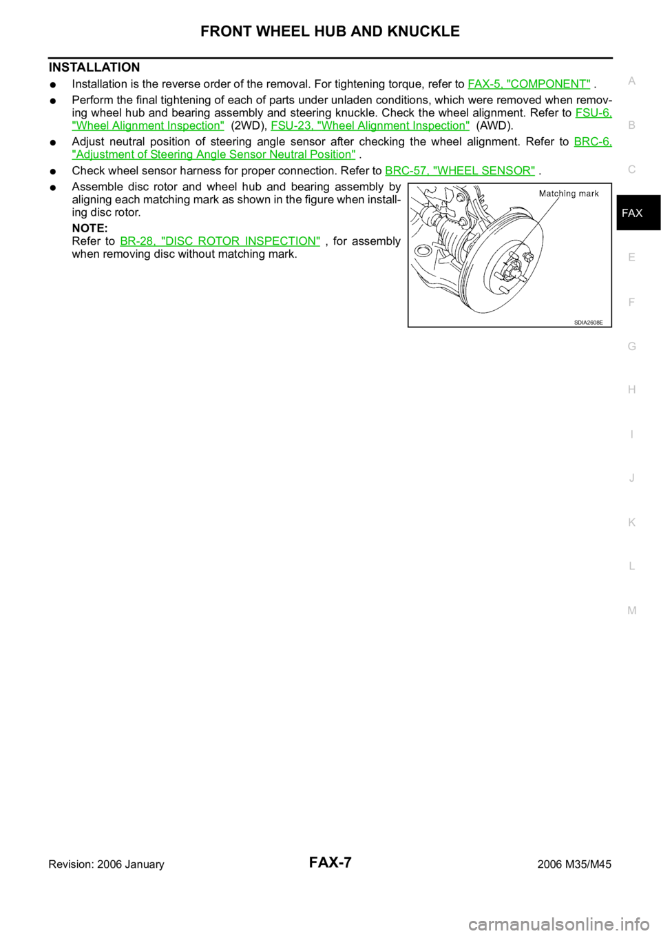
Assemble disc rotor and wheel hub and bearing assembly by
aligning each matching mark as shown in the figure when install-
ing disc rotor.
NOTE:
Refer to BR-28, "
DISC ROTOR INSPECTION" , for assembly
when removing disc without matching mark.
SDIA2608E
Page 3378 of 5621

FFD-1
FRONT FINAL DRIVE
D DRIVELINE/AXLE
CONTENTS
C
E
F
G
H
I
J
K
L
M
SECTION FFD
A
B
FFD
Revision: 2006 January2006 M35/M45
FRONT FINAL DRIVE
PRECAUTIONS .......................................................... 2
Precautions Necessary for Steering Wheel Rotation
after Battery Disconnect ........................................... 2
OPERATION PROCEDURE ................................. 2
Service Notice or Precautions .................................. 2
PREPARATION ........................................................... 3
Special Service Tools ............................................... 3
Commercial Service Tools ........................................ 5
NOISE, VIBRATION AND HARSHNESS (NVH)
TROUBLESHOOTING ................................................ 6
NVH Troubleshooting Chart ..................................... 6
DESCRIPTION ............................................................ 7
Cross-Sectional View ............................................... 7
DIFFERENTIAL GEAR OIL ........................................ 8
Changing Differential Gear Oil ................................. 8
DRAINING ............................................................. 8
FILLING ................................................................. 8
Checking Differential Gear Oil .................................. 8
OIL LEAKAGE AND OIL LEVEL ........................... 8
FRONT OIL SEAL .................................................
..... 9
Removal and Installation .......................................... 9
REMOVAL ........................................................
..... 9
INSTALLATION ................................................... 10SIDE OIL SEAL ......................................................... 11
Removal and Installation ........................................ 11
REMOVAL ........................................................
... 11
INSTALLATION ................................................... 11
FRONT FINAL DRIVE ASSEMBLY .......................... 13
Removal and Installation ........................................ 13
COMPONENTS ................................................... 13
REMOVAL ........................................................
... 13
INSTALLATION ................................................... 14
Disassembly and Assembly .................................... 15
COMPONENTS ................................................... 15
ASSEMBLY INSPECTION AND ADJUSTMENT ... 16
DISASSEMBLY ................................................... 20
INSPECTION AFTER DISASSEMBLY ................ 24
ADJUSTMENT AND SELECTION OF ADJUST-
ING WASHERS (SHIMS) .................................... 25
ASSEMBLY ......................................................... 28
SERVICE DATA AND SPECIFICATIONS (SDS) ...... 35
General Specifications ......................................... ... 35
Inspection and Adjustment ..................................... 35
DRIVE GEAR RUNOUT ...................................... 35
DIFFERENTIAL SIDE GEAR CLEARANCE ....... 35
PRELOAD TORQUE ........................................... 35
BACKLASH ......................................................... 35
COMPANION FLANGE RUNOUT ....................... 35
SELECTIVE PARTS ............................................ 35
Page 3425 of 5621

FL-12
FUEL TANK
Revision: 2006 January2006 M35/M45
2. Start engine and rev it up and make sure there are no fuel leaks at the fuel system tube and hose connec-
tions.
After removing/installing rear suspension assembly, make sure to adjust wheel alignment and then, adjust
neutral position of steering angle sensor. Refer to RSU-5, "
Wheel Alignment Inspection" and BRC-6,
"Adjustment of Steering Angle Sensor Neutral Position" .
Page 4778 of 5621

MA-1
MAINTENANCE
L MAINTENANCE
CONTENTS
C
D
E
F
G
H
I
J
K
M
SECTION MA
A
B
MA
Revision: 2006 January2006 M35/M45
MAINTENANCE
PREPARATION ........................................................... 3
Special Service Tools ............................................... 3
Commercial Service Tools ........................................ 3
GENERAL MAINTENANCE ....................................... 4
Explanation of General Maintenance ....................... 4
PERIODIC MAINTENANCE ....................................... 7
Introduction of Periodic Maintenance ....................... 7
Schedule 1 ............................................................... 8
EMISSION CONTROL SYSTEM MAINTE-
NANCE .................................................................. 8
CHASSIS AND BODY MAINTENANCE ............... 9
Schedule 2 ............................................................. 10
EMISSION CONTROL SYSTEM MAINTE-
NANCE ................................................................ 10
CHASSIS AND BODY MAINTENANCE .............. 11
RECOMMENDED FLUIDS AND LUBRICANTS ...... 12
Fluids and Lubricants ............................................. 12
SAE Viscosity Number ........................................... 13
GASOLINE ENGINE OIL .................................... 13
Anti-Freeze Coolant Mixture Ratio ......................... 13
ENGINE MAINTENANCE (VQ35DE ENGINE) ......... 14
Checking Drive Belts .............................................. 14
Drive Belts Tension Adjustment ............................. 14
ALTERNATOR AND POWER STEERING OIL
PUMP BELT ........................................................ 15
A/C COMPRESSOR BELT ................................. 15
Changing Engine Coolant ...................................... 15
DRAINING ENGINE COOLANT ......................... 15
REFILLING ENGINE COOLANT ........................ 16
FLUSHING COOLING SYSTEM ......................... 17
Checking Fuel Lines ............................................ ... 18
Changing Air Cleaner Filter .................................... 18
VISCOUS PAPER TYPE ..................................... 18
Changing Engine Oil .............................................. 18
Changing Oil Filter ................................................. 19
REMOVAL ........................................................
... 19
INSTALLATION ................................................... 19
INSPECTION AFTER INSTALLATION ............... 20
Changing Spark Plugs (Platinum-Tipped Type) ..... 20
REMOVAL ........................................................
... 20INSPECTION AFTER REMOVAL ....................... 21
INSTALLATION ................................................... 21
Checking EVAP Vapor Lines .................................. 21
ENGINE MAINTENANCE (VK45DE ENGINE) ......... 22
Checking Drive Belts .............................................. 22
Tension Adjustment .............................................
... 22
Changing Engine Coolant ....................................... 22
DRAINING ENGINE COOLANT .......................... 22
REFILLING ENGINE COOLANT ......................... 23
FLUSHING COOLING SYSTEM ......................... 24
Checking Fuel Lines ............................................ ... 25
Changing Air Cleaner Filter .................................... 25
VISCOUS PAPER TYPE ..................................... 25
Changing Engine Oil ............................................
... 25
Changing Oil Filter .................................................. 26
REMOVAL ........................................................
... 26
INSTALLATION ................................................... 26
INSPECTION AFTER INSTALLATION ................ 27
Changing Spark Plugs (Platinum-Tipped Type) ...... 27
REMOVAL ........................................................
... 27
INSPECTION AFTER REMOVAL ....................... 27
INSTALLATION ................................................... 28
Checking EVAP Vapor Lines .................................. 28
CHASSIS AND BODY MAINTENANCE ................... 29
Checking Exhaust System ...................................... 29
Checking A/T Fluid ................................................. 29
Changing A/T Fluid ................................................. 31
Checking Transfer Fluid ......................................... 31
Changing Transfer Fluid ......................................... 32
Checking Propeller Shaft ........................................ 32
Checking Differential Gear Oil ................................ 32
Changing Differential Gear Oil ................................ 33
Balancing Wheels (Bonding Weight Type) ............. 33
REMOVAL ........................................................
... 33
WHEEL BALANCE ADJUSTMENT ..................... 33
Tire Rotation ........................................................... 35
Checking Brake Fluid Level and Leaks .................. 35
Checking Brake Lines and Cables ......................... 35
Changing Brake Fluid ............................................. 35
Checking Disc Brake .............................................. 36
Page 4963 of 5621
PS-10
STEERING WHEEL
Revision: 2006 January2006 M35/M45
STEERING WHEELPFP:48430
On-Vehicle Inspection and ServiceNGS000D8
CHECKING CONDITION OF INSTALLATION
Check installation conditions of steering gear assembly, front suspension assembly, axle and steering col-
umn assembly.
Check if movement exists when steering wheel is moved up and down, to the left and right and to the axial
direction.
Check steering gear assembly mounting bolts and nut for looseness. Refer to PS-18, "COMPONENTS" .
CHECKING STEERING WHEEL PLAY
Turn steering wheel so that front wheels come to the straight-ahead position. Start engine and lightly turn
steering wheel to the left and right until front wheels start to move. Measure steering wheel movement on
the outer circumference.
When the measurement value is outside the standard value, check backlash for each joint of steering col-
umn assembly and installation condition of steering gear assembly.
CHECKING NEUTRAL POSITION STEERING WHEEL
Make sure that steering gear assembly, steering column assembly and steering wheel are installed in the
correct position.
Perform neutral position inspection after wheel alignment. Refer to FSU-6, "Wheel Alignment Inspection"
(2WD), FSU-23, "Wheel Alignment Inspection" (AWD).
Set vehicle to the straight-ahead position and confirm steering wheel is in the neutral position.
Loosen outer socket lock nut and turn inner socket to left and right equally to make fine adjustments if
steering wheel is not in the neutral position.
CHECKING STEERING WHEEL TURNING FORCE
1. Park vehicle on a level and dry surface, set parking brake.
2. Start engine.
3. Bring power steering fluid up to adequate operating temperature. [Make sure temperature of fluid is
approximately 50 to 80
C (122 to 176F).]
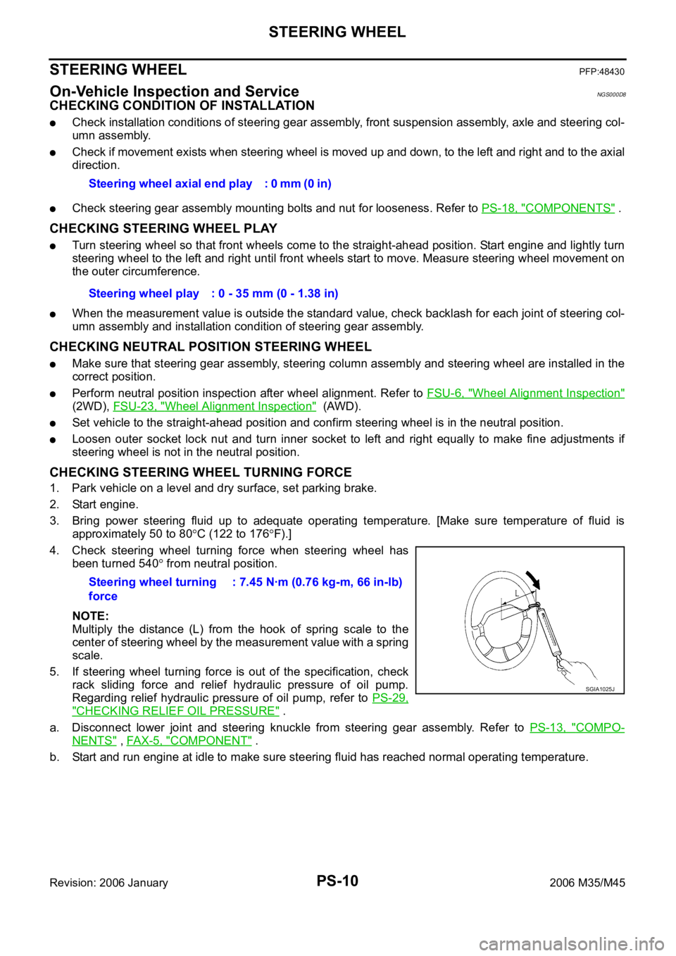
4. Check steering wheel turning force when steering wheel has
been turned 540
from neutral position.
NOTE:
Multiply the distance (L) from the hook of spring scale to the
center of steering wheel by the measurement value with a spring
scale.
5. If steering wheel turning force is out of the specification, check
rack sliding force and relief hydraulic pressure of oil pump.
Regarding relief hydraulic pressure of oil pump, refer to PS-29,
"CHECKING RELIEF OIL PRESSURE" .
a. Disconnect lower joint and steering knuckle from steering gear assembly. Refer to PS-13, "
COMPO-
NENTS" , FAX-5, "COMPONENT" .
b. Start and run engine at idle to make sure steering fluid has reached normal operating temperature. Steering wheel axial end play : 0 mm (0 in)
Steering wheel play : 0 - 35 mm (0 - 1.38 in)
Steering wheel turning
force: 7.45 Nꞏm (0.76 kg-m, 66 in-lb)
SGIA1025J
Page 4968 of 5621
STEERING COLUMN
PS-15
C
D
E
F
H
I
J
K
L
MA
B
PS
Revision: 2006 January2006 M35/M45
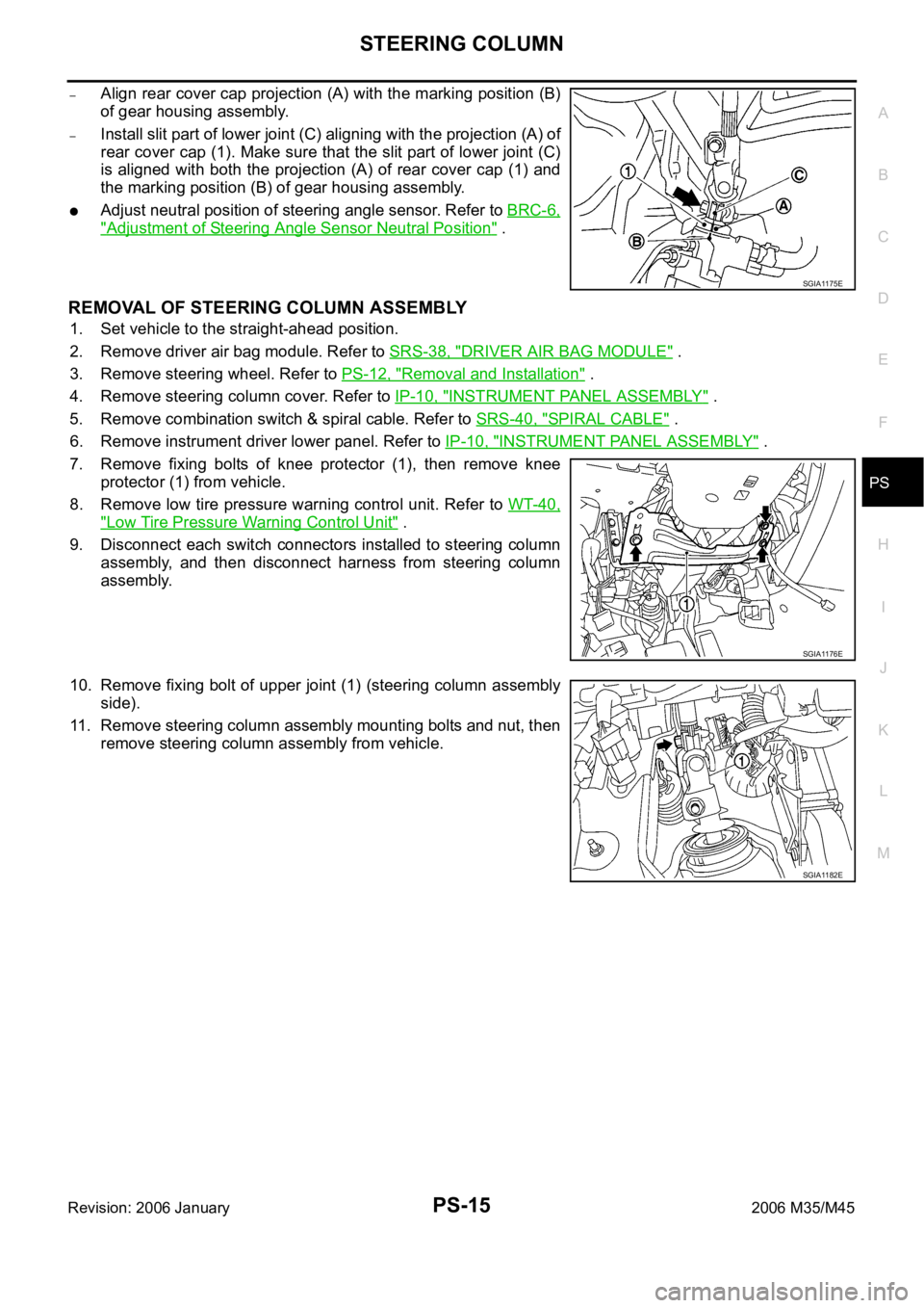
–Align rear cover cap projection (A) with the marking position (B)
of gear housing assembly.
–Install slit part of lower joint (C) aligning with the projection (A) of
rear cover cap (1). Make sure that the slit part of lower joint (C)
is aligned with both the projection (A) of rear cover cap (1) and
the marking position (B) of gear housing assembly.
Adjust neutral position of steering angle sensor. Refer to BRC-6,
"Adjustment of Steering Angle Sensor Neutral Position" .
REMOVAL OF STEERING COLUMN ASSEMBLY
1. Set vehicle to the straight-ahead position.
2. Remove driver air bag module. Refer to SRS-38, "
DRIVER AIR BAG MODULE" .
3. Remove steering wheel. Refer to PS-12, "
Removal and Installation" .
4. Remove steering column cover. Refer to IP-10, "
INSTRUMENT PANEL ASSEMBLY" .
5. Remove combination switch & spiral cable. Refer to SRS-40, "
SPIRAL CABLE" .
6. Remove instrument driver lower panel. Refer to IP-10, "
INSTRUMENT PANEL ASSEMBLY" .
7. Remove fixing bolts of knee protector (1), then remove knee
protector (1) from vehicle.
8. Remove low tire pressure warning control unit. Refer to WT-40,
"Low Tire Pressure Warning Control Unit" .
9. Disconnect each switch connectors installed to steering column
assembly, and then disconnect harness from steering column
assembly.
10. Remove fixing bolt of upper joint (1) (steering column assembly
side).
11. Remove steering column assembly mounting bolts and nut, then
remove steering column assembly from vehicle.
SGIA1175E
SGIA1176E
SGIA1182E
Page 4969 of 5621
PS-16
STEERING COLUMN
Revision: 2006 January2006 M35/M45
INSPECTION AFTER REMOVAL
Check each part of steering column assembly for damage or other malfunctions. Replace if there are.
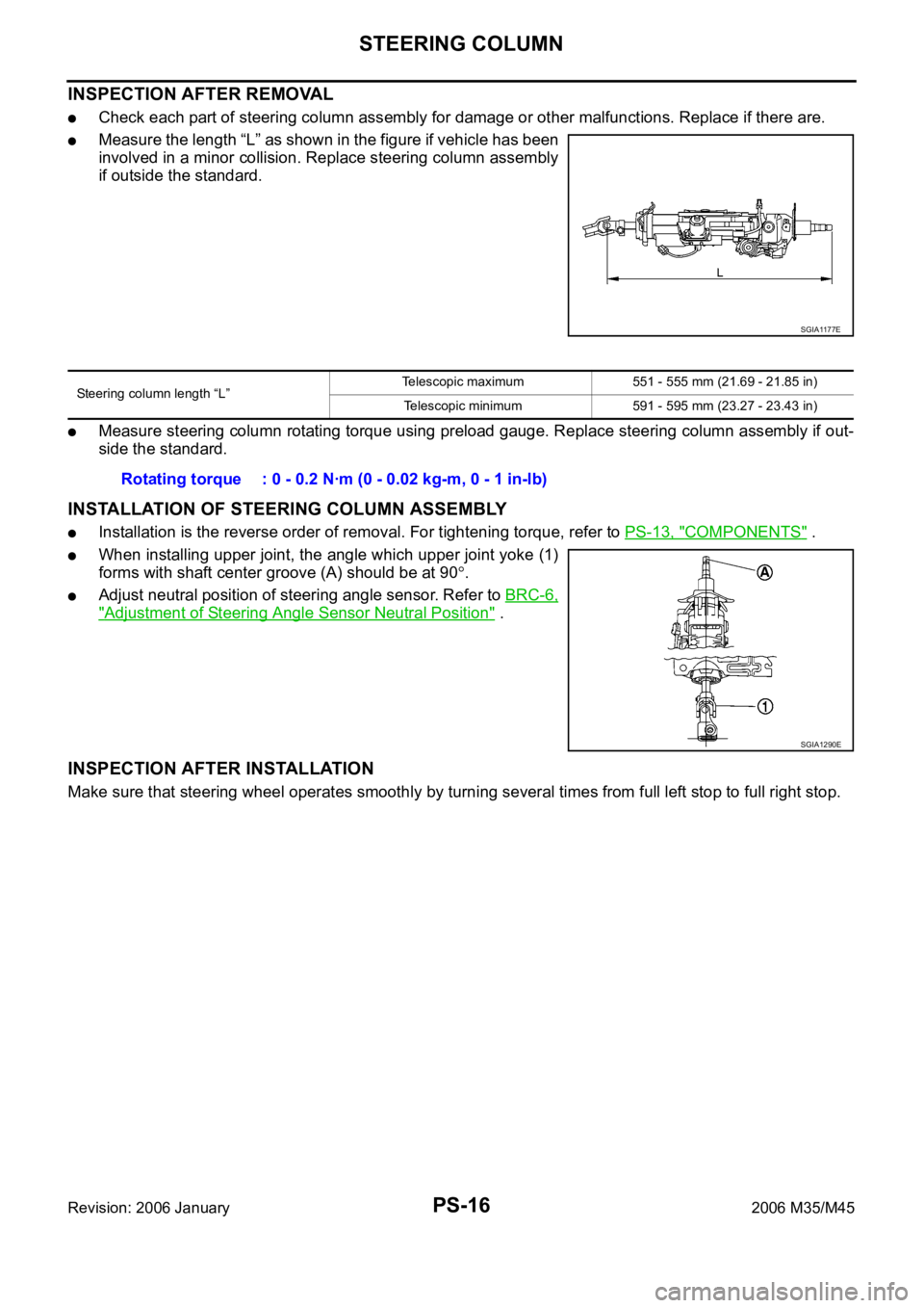
Measure the length “L” as shown in the figure if vehicle has been
involved in a minor collision. Replace steering column assembly
if outside the standard.
Measure steering column rotating torque using preload gauge. Replace steering column assembly if out-
side the standard.
INSTALLATION OF STEERING COLUMN ASSEMBLY
Installation is the reverse order of removal. For tightening torque, refer to PS-13, "COMPONENTS" .
When installing upper joint, the angle which upper joint yoke (1)
forms with shaft center groove (A) should be at 90
.
Adjust neutral position of steering angle sensor. Refer to BRC-6,
"Adjustment of Steering Angle Sensor Neutral Position" .
INSPECTION AFTER INSTALLATION
Make sure that steering wheel operates smoothly by turning several times from full left stop to full right stop.
SGIA1177E
Steering column length “L”Telescopic maximum 551 - 555 mm (21.69 - 21.85 in)
Telescopic minimum 591 - 595 mm (23.27 - 23.43 in)
Rotating torque : 0 - 0.2 Nꞏm (0 - 0.02 kg-m, 0 - 1 in-lb)
SGIA1290E
Page 5089 of 5621
RSU-8
REAR SUSPENSION ASSEMBLY
Revision: 2006 January2006 M35/M45
Refer to GI section for symbol marks in the figure. Refer to GI-9, "HOW TO USE THIS MANUAL" .
Removal and InstallationNES000J9
REMOVAL
1. Remove tire with a power tool.
2. Remove brake caliper with a power tool. Hang it in a place where it will not interfere with work. Refer to
BR-29, "
REAR DISC BRAKE" .
CAUTION:
Do not depressing brake pedal while brake caliper is removed.
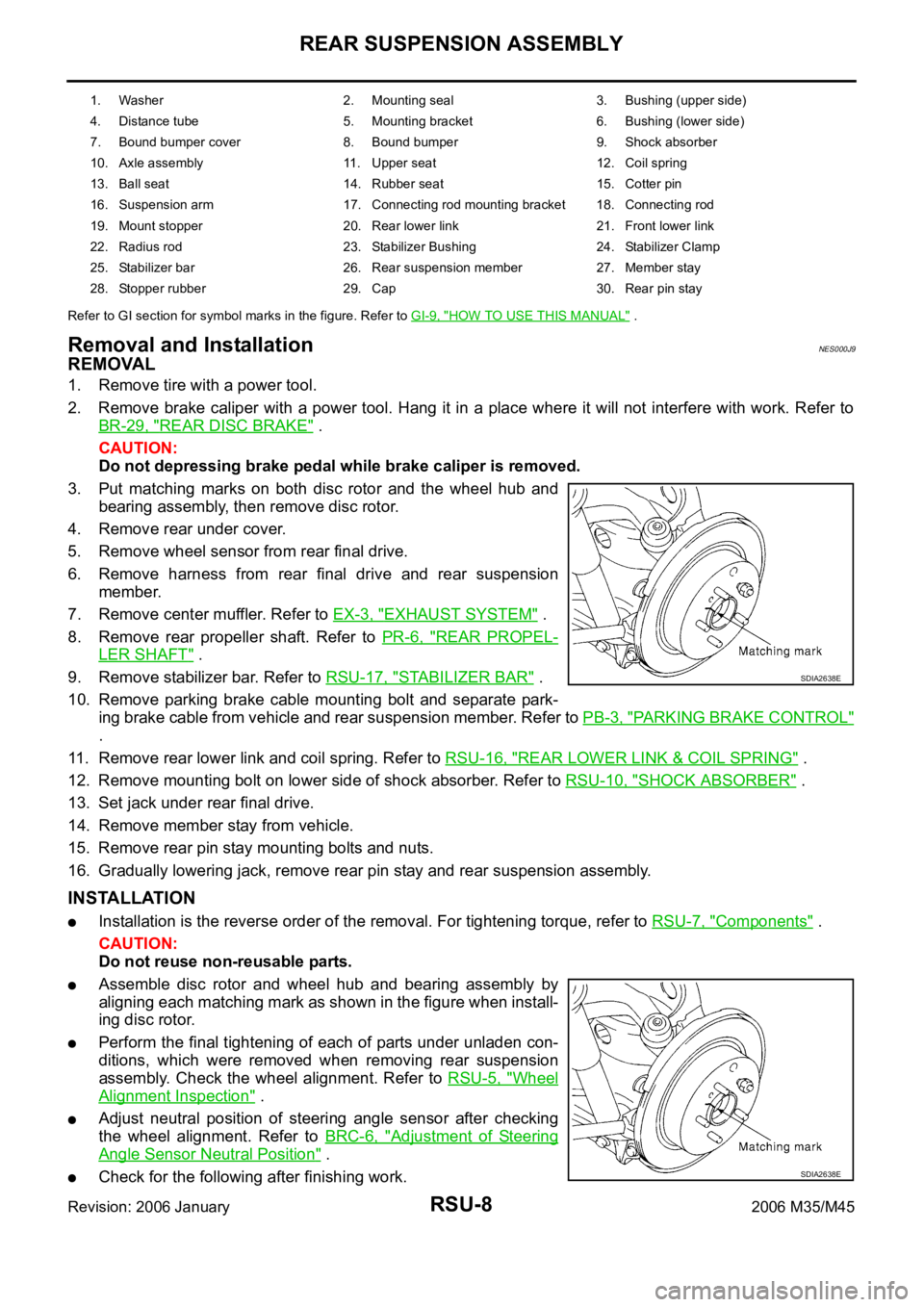
3. Put matching marks on both disc rotor and the wheel hub and
bearing assembly, then remove disc rotor.
4. Remove rear under cover.
5. Remove wheel sensor from rear final drive.
6. Remove harness from rear final drive and rear suspension
member.
7. Remove center muffler. Refer to EX-3, "
EXHAUST SYSTEM" .
8. Remove rear propeller shaft. Refer to PR-6, "
REAR PROPEL-
LER SHAFT" .
9. Remove stabilizer bar. Refer to RSU-17, "
STABILIZER BAR" .
10. Remove parking brake cable mounting bolt and separate park-
ing brake cable from vehicle and rear suspension member. Refer to PB-3, "
PARKING BRAKE CONTROL"
.
11. Remove rear lower link and coil spring. Refer to RSU-16, "
REAR LOWER LINK & COIL SPRING" .
12. Remove mounting bolt on lower side of shock absorber. Refer to RSU-10, "
SHOCK ABSORBER" .
13. Set jack under rear final drive.
14. Remove member stay from vehicle.
15. Remove rear pin stay mounting bolts and nuts.
16. Gradually lowering jack, remove rear pin stay and rear suspension assembly.
INSTALLATION
Installation is the reverse order of the removal. For tightening torque, refer to RSU-7, "Components" .
CAUTION:
Do not reuse non-reusable parts.
Assemble disc rotor and wheel hub and bearing assembly by
aligning each matching mark as shown in the figure when install-
ing disc rotor.
Perform the final tightening of each of parts under unladen con-
ditions, which were removed when removing rear suspension
assembly. Check the wheel alignment. Refer to RSU-5, "
Wheel
Alignment Inspection" .
Adjust neutral position of steering angle sensor after checking
the wheel alignment. Refer to BRC-6, "
Adjustment of Steering
Angle Sensor Neutral Position" .
Check for the following after finishing work.
1. Washer 2. Mounting seal 3. Bushing (upper side)
4. Distance tube 5. Mounting bracket 6. Bushing (lower side)
7. Bound bumper cover 8. Bound bumper 9. Shock absorber
10. Axle assembly 11. Upper seat 12. Coil spring
13. Ball seat 14. Rubber seat 15. Cotter pin
16. Suspension arm 17. Connecting rod mounting bracket 18. Connecting rod
19. Mount stopper 20. Rear lower link 21. Front lower link
22. Radius rod 23. Stabilizer Bushing 24. Stabilizer Clamp
25. Stabilizer bar 26. Rear suspension member 27. Member stay
28. Stopper rubber 29. Cap 30. Rear pin stay
SDIA2638E
SDIA2638E