2006 INFINITI M35 steering wheel adjustment
[x] Cancel search: steering wheel adjustmentPage 5091 of 5621
RSU-10
SHOCK ABSORBER
Revision: 2006 January2006 M35/M45
SHOCK ABSORBERPFP:56210
Removal and InstallationNES000JA
REMOVAL
1. Remove tires from vehicle with a power tool.
2. Set a jack under rear lower link to relieve the coil spring tension.
3. Remove shock absorber lower end bolt with a power tool.
4. Gradually lower the jack to remove it from rear lower link.
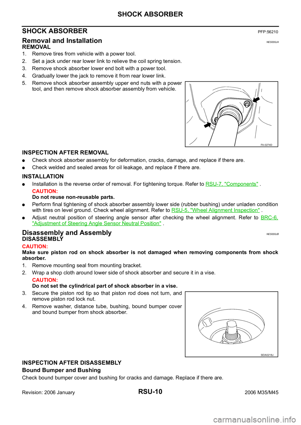
5. Remove shock absorber assembly upper end nuts with a power
tool, and then remove shock absorber assembly from vehicle.
INSPECTION AFTER REMOVAL
Check shock absorber assembly for deformation, cracks, damage, and replace if there are.
Check welded and sealed areas for oil leakage, and replace if there are.
INSTALLATION
Installation is the reverse order of removal. For tightening torque. Refer to RSU-7, "Components" .
CAUTION:
Do not reuse non-reusable parts.
Perform final tightening of shock absorber assembly lower side (rubber bushing) under unladen condition
with tires on level ground. Check wheel alignment. Refer to RSU-5, "
Wheel Alignment Inspection" .
Adjust neutral position of steering angle sensor after checking the wheel alignment. Refer to BRC-6,
"Adjustment of Steering Angle Sensor Neutral Position" .
Disassembly and AssemblyNES000JB
DISASSEMBLY
CAUTION:
Make sure piston rod on shock absorber is not damaged when removing components from shock
absorber.
1. Remove mounting seal from mounting bracket.
2. Wrap a shop cloth around lower side of shock absorber and secure it in a vise.
CAUTION:
Do not set the cylindrical part of shock absorber in a vise.
3. Secure the piston rod tip so that piston rod does not turn, and
remove piston rod lock nut.
4. Remove washer, distance tube, bushing, bound bumper cover
and bound bumper from shock absorber.
INSPECTION AFTER DISASSEMBLY
Bound Bumper and Bushing
Check bound bumper cover and bushing for cracks and damage. Replace if there are.
FA-0274D
SEIA0218J
Page 5094 of 5621
SUSPENSION ARM
RSU-13
C
D
F
G
H
I
J
K
L
MA
B
RSU
Revision: 2006 January2006 M35/M45
If it is outside the specified range, replace suspension arm assembly.
INSTALLATION
Installation is the reverse order of removal. For tightening torque. Refer to RSU-7, "Components" .
CAUTION:
Do not reuse non-reusable parts.
Perform the final tightening of rear suspension member installation position (rubber bushing) under
unladen condition with tires on level ground. Refer to RSU-5, "
Wheel Alignment Inspection" .
Adjust neutral position of steering angle sensor after checking the wheel alignment. Refer to BRC-6,
"Adjustment of Steering Angle Sensor Neutral Position" .
Page 5095 of 5621
RSU-14
RADIUS ROD
Revision: 2006 January2006 M35/M45
RADIUS RODPFP:55110
Removal and InstallationNES000JD
REMOVAL
1. Remove tire with a power tool.
2. Remove brake caliper with a power tool. Hang it in a place where it will not interfere with work. Refer to
BR-29, "
REAR DISC BRAKE" .
CAUTION:
Do not depressing brake pedal while brake caliper is removed.
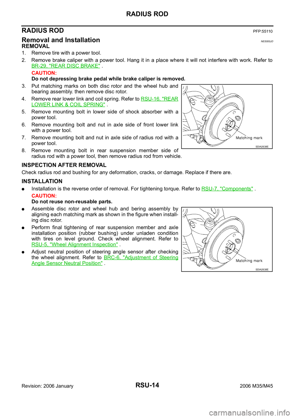
3. Put matching marks on both disc rotor and the wheel hub and
bearing assembly. then remove disc rotor.
4. Remove rear lower link and coil spring. Refer to RSU-16, "
REAR
LOWER LINK & COIL SPRING" .
5. Remove mounting bolt in lower side of shock absorber with a
power tool.
6. Remove mounting bolt and nut in axle side of front lower link
with a power tool.
7. Remove mounting bolt and nut in axle side of radius rod with a
power tool.
8. Remove mounting bolt in rear suspension member side of
radius rod with a power tool, then remove radius rod from vehicle.
INSPECTION AFTER REMOVAL
Check radius rod and bushing for any deformation, cracks, or damage. Replace if there are.
INSTALLATION
Installation is the reverse order of removal. For tightening torque. Refer to RSU-7, "Components" .
CAUTION:
Do not reuse non-reusable parts.
Assemble disc rotor and wheel hub and bering assembly by
aligning each matching mark as shown in the figure when install-
ing disc rotor.
Perform final tightening of rear suspension member and axle
installation position (rubber bushing) under unladen condition
with tires on level ground. Check wheel alignment. Refer to
RSU-5, "
Wheel Alignment Inspection" .
Adjust neutral position of steering angle sensor after checking
the wheel alignment. Refer to BRC-6, "
Adjustment of Steering
Angle Sensor Neutral Position" .
SDIA2638E
SDIA2638E
Page 5096 of 5621
FRONT LOWER LINK
RSU-15
C
D
F
G
H
I
J
K
L
MA
B
RSU
Revision: 2006 January2006 M35/M45
FRONT LOWER LINKPFP:55110
Removal and InstallationNES000JE
REMOVAL
1. Remove tire with a power tool.
2. Set a jack under rear lower link to relieve the coil spring tension.
3. Remove mounting nut and bolt between front lower link and rear suspension member with a power tool.
4. Remove mounting nut and bolt between front lower link and axle with a power tool.
5. Remove front lower link from vehicle.
INSPECTION AFTER REMOVAL
Check front lower link and bushing for any deformation, cracks, or damage. Replace if there are.
INSTALLATION
Installation is the reverse order of removal. For tightening torque. Refer to RSU-7, "Components" .
CAUTION:
Do not reuse non-reusable parts.
Perform the final tightening of rear suspension member and axle installation position (rubber bushing)
under unladen condition with tires on level ground. Check wheel alignment. Refer to RSU-5, "
Wheel Align-
ment Inspection" .
Adjust neutral position of steering angle sensor after checking the wheel alignment. Refer to Refer to
BRC-6, "
Adjustment of Steering Angle Sensor Neutral Position" .
Page 5097 of 5621
RSU-16
REAR LOWER LINK & COIL SPRING
Revision: 2006 January2006 M35/M45
REAR LOWER LINK & COIL SPRINGPFP:551B0
Removal and InstallationNES000JF
REMOVAL
1. Remove tire with a power tool.
2. Set a jack under rear lower link to relieve the coil spring tension.
3. Loosen mounting bolt and nut of rear lower link inside of suspension member, and then remove mounting
bolt and nut inside of axle with a power tool.
4. Slowly lower jack, then remove upper seat, coil spring and rubber sheet from rear lower link.
5. Remove mounting bolt and nut inside of suspension member to remove rear lower link with a power tool.
INSPECTION AFTER REMOVAL
Check rear lower link, bushing and coil spring for deformation, cracks, and damage. Replace rear lower link
and coil spring if there are.
INSTALLATION
Installation is the reverse order of removal. For tightening torque. Refer to RSU-7, "Components" .
CAUTION:
Do not reuse non-reusable parts.
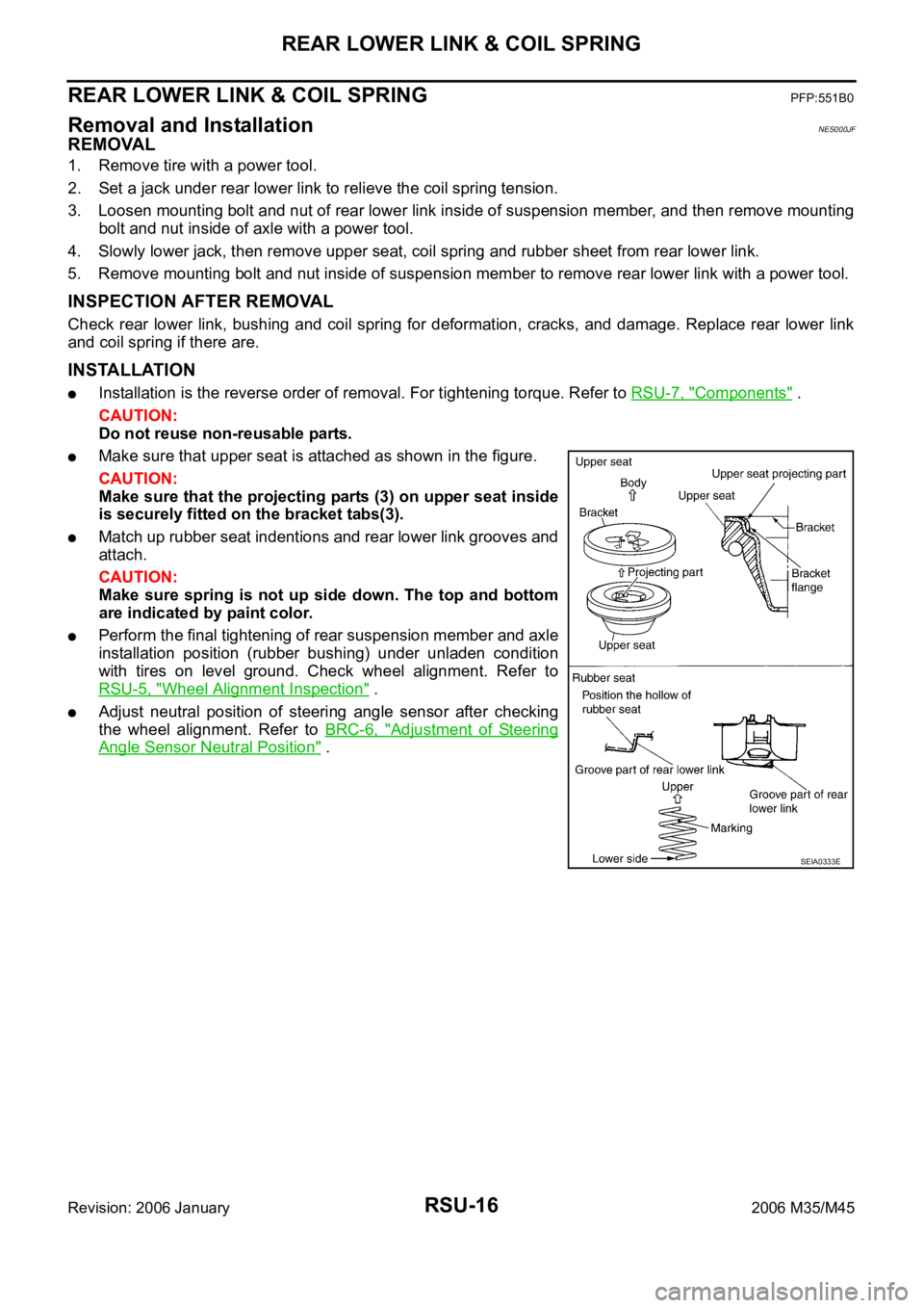
Make sure that upper seat is attached as shown in the figure.
CAUTION:
Make sure that the projecting parts (3) on upper seat inside
is securely fitted on the bracket tabs(3).
Match up rubber seat indentions and rear lower link grooves and
attach.
CAUTION:
Make sure spring is not up side down. The top and bottom
are indicated by paint color.
Perform the final tightening of rear suspension member and axle
installation position (rubber bushing) under unladen condition
with tires on level ground. Check wheel alignment. Refer to
RSU-5, "
Wheel Alignment Inspection" .
Adjust neutral position of steering angle sensor after checking
the wheel alignment. Refer to BRC-6, "
Adjustment of Steering
Angle Sensor Neutral Position" .
SEIA0333E
Page 5193 of 5621

SE-12
AUTOMATIC DRIVE POSITIONER
Revision: 2006 January2006 M35/M45
System DescriptionNIS0025R
The system automatically moves the driver seat, steering and door mirror position by the driver seat con-
trol unit and the automatic drive positioner control unit. The driver seat control unit corresponds with the
automatic drive positioner control unit via UART communication. The driver seat control unit can store the
optimum driving positions (driver seat, steering and door mirror position) for 2 people. If the driver
changes, one-touch operation allows changing to the other driving position.
The driver seat, steering and door mirror position are adjusted automatically to the proper positions for the
driver in different ways: MEMORY OPERATION, EXITING OPERATION, ENTRY OPERATION and
INTELLIGENT KEY INTERLOCK OPERATION.
MANUAL OPERATION
The driving position (seat, steering and door mirror position) can be adjusted with the power seat switch, ADP
steering switch and door mirror control switch.
NOTE:
The door mirrors can be manually operated with the ignition switch in either ACC or ON.
MEMORY OPERATION
The driver seat control unit can store the optimum driving positions (seat, steering and door mirror position) for
2 people. If the front seat position is changed, one-touch (pressing desired memory switch for more than 0.5
second) operation allows changing to the other driving position.
Operation procedure
1. Turn ignition switch ON.
2. Press desired memory switch for 0.5 second. (Indicator LED illuminates.)
3. Driver seat, steering and door mirror will move to the memorized position.
(Indicator LED blinks during adjustment, then illuminates for 5 seconds.)
Operation Condition
If the following conditions are not satisfied, memory switch operation is not performed.
Ignition switch is in ON position.
Driver side power seat switch, ADP steering switch and door mirror control switch are not operated.
Seat memory switch and set switch are not operated.
Output malfunction is not detected.
CAN and UART communications are normal.
A/T selector lever position is in P position.
Detention switch malfunction is not detected.
[Detention switch malfunction is sensed when detention switch remains OFF, vehicle speed is higher than
7 km/H. (4 MPH).]
Input voltage from tilt sensor and telescopic sensor are normal.
NOTE:
The memory operation operates following order.
Function Description
Manual operationThe driving position (seat, steering and door mirror position) can be adjusted with
the power seat switch ADP steering switch or door mirror control switch.
Auto-
matic
operationMemory operation The seat, steering and door mirror move to the stored driving position by pushing
seat memory switch (1 or 2).
Entry/
Exiting
functionExiting operation At exit, the seat moves backward and the steering wheel moves upward.
Entry operationAt entry, the seat and steering wheel returns from exiting position to the previous
driving position before the exiting operation.
Intelligent Key interlock operationPerform memory operation, exiting operation and entry operation by pressing Intel-
ligent Key unlock button.
Page 5429 of 5621
![INFINITI M35 2006 Factory Service Manual STC-14
[RAS]
REAR ACTIVE STEER
Revision: 2006 January2006 M35/M45
Disassembly and AssemblyNGS000E6
COMPONENTS
DISASSEMBLY
1. Remove mounting bolts of RAS motor assembly, and then remove RAS motor asse INFINITI M35 2006 Factory Service Manual STC-14
[RAS]
REAR ACTIVE STEER
Revision: 2006 January2006 M35/M45
Disassembly and AssemblyNGS000E6
COMPONENTS
DISASSEMBLY
1. Remove mounting bolts of RAS motor assembly, and then remove RAS motor asse](/manual-img/42/57023/w960_57023-5428.png)
STC-14
[RAS]
REAR ACTIVE STEER
Revision: 2006 January2006 M35/M45
Disassembly and AssemblyNGS000E6
COMPONENTS
DISASSEMBLY
1. Remove mounting bolts of RAS motor assembly, and then remove RAS motor assembly, ground terminal,
O-ring from RAS actuator.
2. Remove mounting bolt of rear wheel steering angle sensor, and then remove rear wheel steering angle
sensor, O-ring from RAS actuator.
INSPECTION AFTER DISASSEMBLY
Check RAS actuator bracket (rear wheel steering angle sensor mounting area) for crush, deformation, cracks,
or other damage. Replace the RAS actuator malfunction is detected.
ASSEMBLY
Assembly is the reverse order of disassembly. For tightening torque, refer to STC-14, "COMPONENTS" .
After assembling RAS actuator assembly (after removing and installing rear wheel angle sensor and RAS
motor), perform the neutral position adjustment.
Neutral Position AdjustmentNGS000E7
Adjust neutral position after performing the following procedure.
Removing and installing or replacing the RAS actuator assembly
Disassembling the RAS actuator assembly (when removing rear wheel steering angle sensor and RAS
motor)
CAUTION:
Perform the neutral position adjustment after installing the RAS actuator assembly to the vehicle.
Before that, remove the rear lower link from the RAS actuator.
1. Disconnect harness connector and remove rear wheel steering angle sensor from the RAS actuator
assembly.
2. Disconnect RAS motor harness connector.
3. Turn ignition switch ON.
1. Ground terminal 2. RAS motor assembly 3. O-ring
4. RAS actuator 5. Rear wheel steering angle sensor
Refer to GI-11, "
Components" , for the symbols in the figure.
SGIA1052J
Page 5454 of 5621
![INFINITI M35 2006 Factory Service Manual TROUBLE DIAGNOSIS
STC-39
[RAS]
C
D
E
F
H
I
J
K
L
MA
B
STC
Revision: 2006 January2006 M35/M45
3. CHECK STEERING ANGLE SENSOR POWER SUPPLY AND GROUND CIRCUIT
1. Turn ignition switch OFF, and disconnect INFINITI M35 2006 Factory Service Manual TROUBLE DIAGNOSIS
STC-39
[RAS]
C
D
E
F
H
I
J
K
L
MA
B
STC
Revision: 2006 January2006 M35/M45
3. CHECK STEERING ANGLE SENSOR POWER SUPPLY AND GROUND CIRCUIT
1. Turn ignition switch OFF, and disconnect](/manual-img/42/57023/w960_57023-5453.png)
TROUBLE DIAGNOSIS
STC-39
[RAS]
C
D
E
F
H
I
J
K
L
MA
B
STC
Revision: 2006 January2006 M35/M45
3. CHECK STEERING ANGLE SENSOR POWER SUPPLY AND GROUND CIRCUIT
1. Turn ignition switch OFF, and disconnect steering angle sensor harness connector M47.
2. Check continuity steering angle sensor harness connector M47
and ground.
3. Turn ignition switch ON, and then check voltage steering angle
sensor harness connector M47 and ground.
OK or NG
OK >> GO TO 4.
NG >> Steering angle sensor power supply and ground circuit
open or shorted. Repair or replace the applicable mal-
functioning circuit.
4. DATA MONITOR
1. Connect steering angle sensor harness connector.
2. Select ”DATA MONITOR“ on “STEERING ANG” mode, and then check the steering angle.
OK or NG
OK >> RAS control unit malfunction. Replace RAS control unit.
NG >> Replace steering angle sensor and adjust neutral position of steering angle sensor. Refer to BRC-
6, "Adjustment of Steering Angle Sensor Neutral Position" .
Steering angle sensor Ground Continuity
Te r m i n a l 2 — Ye s
SGIA1270E
Steering angle sensor Ground Continuity
Terminal 3 — Battery voltage (approx. 12V)
SGIA1271E
Steering condition DATA MONITOR
Straight-ahead position – 3.5 - +3.5
Turn wheel to the right by 90Approx. R 90
Turn wheel to the left by 90Approx. R 90