2006 INFINITI M35 height adjustment
[x] Cancel search: height adjustmentPage 1281 of 5621
BR-6
BRAKE PEDAL
Revision: 2006 January2006 M35/M45
BRAKE PEDALPFP:46501
Inspection and AdjustmentNFS000OS
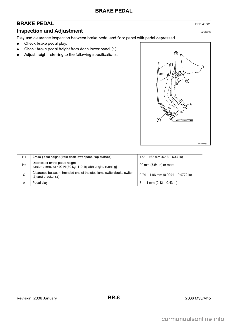
Play and clearance inspection between brake pedal and floor panel with pedal depressed.
Check brake pedal play.
Check brake pedal height from dash lower panel (1).
Adjust height referring to the following specifications.
SFIA2743J
H1Brake pedal height (from dash lower panel top surface) 157 167 mm (6.18 6.57 in)
H
2Depressed brake pedal height
[under a force of 490 N (50 kg, 110 lb) with engine running]90 mm (3.54 in) or more
CClearance between threaded end of the stop lamp switch/brake switch
(2) and bracket (3)0.74
1.96 mm (0.0291 0.0772 in)
A Pedal play 3
11 mm (0.12 0.43 in)
Page 1282 of 5621
BRAKE PEDAL
BR-7
C
D
E
G
H
I
J
K
L
MA
B
BR
Revision: 2006 January2006 M35/M45
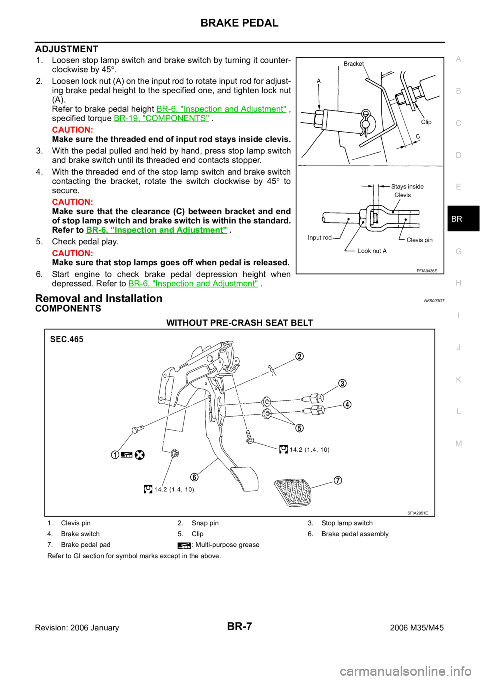
ADJUSTMENT
1. Loosen stop lamp switch and brake switch by turning it counter-
clockwise by 45
.
2. Loosen lock nut (A) on the input rod to rotate input rod for adjust-
ing brake pedal height to the specified one, and tighten lock nut
(A).
Refer to brake pedal height BR-6, "
Inspection and Adjustment" ,
specified torque BR-19, "
COMPONENTS" .
CAUTION:
Make sure the threaded end of input rod stays inside clevis.
3. With the pedal pulled and held by hand, press stop lamp switch
and brake switch until its threaded end contacts stopper.
4. With the threaded end of the stop lamp switch and brake switch
contacting the bracket, rotate the switch clockwise by 45
to
secure.
CAUTION:
Make sure that the clearance (C) between bracket and end
of stop lamp switch and brake switch is within the standard.
Refer to BR-6, "
Inspection and Adjustment" .
5. Check pedal play.
CAUTION:
Make sure that stop lamps goes off when pedal is released.
6. Start engine to check brake pedal depression height when
depressed. Refer to BR-6, "
Inspection and Adjustment" .
Removal and InstallationNFS000OT
COMPONENTS
WITHOUT PRE-CRASH SEAT BELT
PFIA0436E
SFIA2951E
1. Clevis pin 2. Snap pin 3. Stop lamp switch
4. Brake switch 5. Clip 6. Brake pedal assembly
7. Brake pedal pad : Multi-purpose grease
Refer to GI section for symbol marks except in the above.
Page 1284 of 5621
BRAKE PEDAL
BR-9
C
D
E
G
H
I
J
K
L
MA
B
BR
Revision: 2006 January2006 M35/M45
INSTALLATION
Installation is the reverse order of removal. Tightening torques for brake pedal assembly mounting nuts and
bolt are referred to BR-7, "
COMPONENTS" . Tightening torque for lock nut is referred to BR-19, "COMPO-
NENTS" .
Adjust brake pedal height after installing brake pedal assembly to vehicle. Refer to BR-6, "Inspection and
Adjustment" .
CAUTION:
Do not reuse clevis pin.
Page 1295 of 5621
BR-20
BRAKE BOOSTER
Revision: 2006 January2006 M35/M45
4. Install brake pedal bracket mounting nuts and bolt, and tighten them to the specified torque. Refer to BR-
7, "COMPONENTS" .
5. Install vacuum hose into brake booster. Refer to BR-22, "
Removal and Installation" .
6. Install master cylinder to booster assembly. Refer to BR-15, "
Removal and Installation" .
7. Adjust the brake pedal height and the play of the brake pedal. Refer to BR-7, "
ADJUSTMENT" .
8. Tighten lock nut of input rod to the specified torque. Refer to BR-19, "
COMPONENTS" .
9. Connect front left brake tube to ABS actuator and electric unit (control unit). Refer to BR-12, "
Hydraulic
Circuit" .
10. Install cowl top. Refer to EI-18, "
Removal and Installation" .
11. Refill new brake fluid and bleed air. Refer to BR-11, "
Bleeding Brake System" .
Page 1435 of 5621
DI-2Revision: 2006 January2006 M35/M45 A/T INDICATOR ........................................................ 56
System Description ................................................. 56
MANUAL MODE .................................................. 56
NOT MANUAL MODE ......................................... 56
Wiring Diagram — AT/IND — ................................. 57
A/T Indicator Is Malfunction .................................... 59
WARNING CHIME .................................................. ... 60
System Description ................................................. 60
POWER SUPPLY AND GROUND CIRCUIT ....... 60
IGNITION KEY WARNING CHIME (WITH INTEL-
LIGENT KEY) ...................................................... 61
LIGHT WARNING CHIME ................................... 61
SEAT BELT WARNING CHIME ........................... 61
Component Parts and Harness Connector Location ... 62
Schematic ............................................................... 63
Wiring Diagram — CHIME — ................................. 64
Terminals and Reference Value for Combination
Meter ...................................................................... 67
Terminals and Reference Value for Unified Meter
and A/C Amp. ......................................................... 67
Terminals and Reference Value for BCM ................ 68
CONSULT-II Function (BCM) .................................. 69
CONSULT-II BASIC OPERATION ....................... 69
DATA MONITOR .................................................. 70
ACTIVE TEST ..................................................... 71
SELF-DIAG RESULTS ........................................ 71
CONSULT-II Function (METER A/C AMP) ............. 71
Trouble Diagnosis ................................................... 71
HOW TO PERFORM TROUBLE DIAGNOSIS .... 71
PRELIMINARY INSPECTION ............................. 71
SYMPTOM CHART ............................................. 72
Meter Buzzer Circuit Inspection .............................. 72
Lighting Switch Signal Inspection ........................... 73
Front Door Switch (Driver Side) Signal Inspection ... 73
Seat Belt Buckle Switch Signal Inspection ............. 74
Electrical Component Inspection ............................ 76
FRONT DOOR SWITCH (DRIVER SIDE) ........... 76
SEAT BELT BUCKLE SWITCH (DRIVER SIDE) ... 76
CAN COMMUNICATION ........................................... 77
System Description ................................................. 77
CAN Communication Unit ....................................... 77
LANE DEPARTURE WARNING SYSTEM ................ 78
Precautions for Lane Departure Warning (LDW)
system .................................................................... 78
System Description ................................................. 78
LDW SYSTEM OPERATION ............................... 78
POWER SUPPLY AND GROUND CIRCUIT ....... 80
Action Test ...........................................................
... 80
LDW SYSTEM RUNNING TEST ......................... 80
Camera Aiming Adjustment .................................... 81
OUTLINE ............................................................. 81
PREPARATION ................................................... 81TARGET SETTING .............................................. 81
VEHICLE HEIGHT CHECK ................................. 84
AIMING ADJUSTMENT ....................................... 84
Component Parts and Harness Connector Location ... 88
Wiring Diagram — LDW — ..................................... 89
Terminals and Reference Value for LDW Camera
Unit .......................................................................... 91
CONSULT-II Function (LDW) .................................. 91
DESCRIPTION .................................................... 91
CONSULT-II BASIC OPERATION ....................... 91
WORK SUPPORT ............................................... 92
SELF-DIAG RESULTS ......................................... 92
DATA MONITOR .................................................. 93
ACTIVE TEST ...................................................... 94
Trouble Diagnosis ................................................... 95
HOW TO PERFORM TROUBLE DIAGNOSIS .... 95
PRELIMINARY INSPECTION .............................. 95
SYMPTOM CHART .............................................. 96
Power Supply and Ground Circuit Inspection ......... 96
DTC [C1B00] CAMERA UNIT MALF ...................... 97
DTC [C1B01] CAM AIMING INCMP ....................... 97
DTC [C1B02] VHCL SPD DATA MALF ................... 97
DTC [C1B03] ABNRML TEMP DETECT ................ 97
DTC [U1000] CAN COMM CIRCUIT ...................... 98
DTC [U1010] CONTROL UNIT (CAN) .................... 98
LDW Chime Circuit Inspection ................................ 98
LDW Switch Circuit Inspection ................................ 99
LDW Indicator Lamp Circuit Inspection .................102
Turn Signal Input Inspection .................................103
Electrical Component Inspection ..........................103
LDW SWITCH ....................................................103
Removal and Installation for LDW Camera Unit ...103
REMOVAL ..........................................................103
INSTALLATION ..................................................103
Removal and Installation for LDW Chime .............104
REMOVAL ..........................................................104
INSTALLATION ..................................................104
Removal and Installation for LDW Switch .............104
COMPASS ...............................................................105
System Description ...............................................105
DIRECTION DISPLAY .......................................105
Zone Variation Change Procedure ........................105
Correction Functions of the Compass Display ......105
AUTOMATIC CORRECTION .............................105
MANUAL CORRECTION PROCEDURE ...........105
Wiring Diagram – COMPAS – ...............................106
Removal and Installation of Compass ...................107
CLOCK ....................................................................108
Wiring Diagram — CLOCK — ...............................108
Removal and Installation of Clock .........................109
REMOVAL ..........................................................109
INSTALLATION ..................................................109
Page 1517 of 5621
DI-84
LANE DEPARTURE WARNING SYSTEM
Revision: 2006 January2006 M35/M45
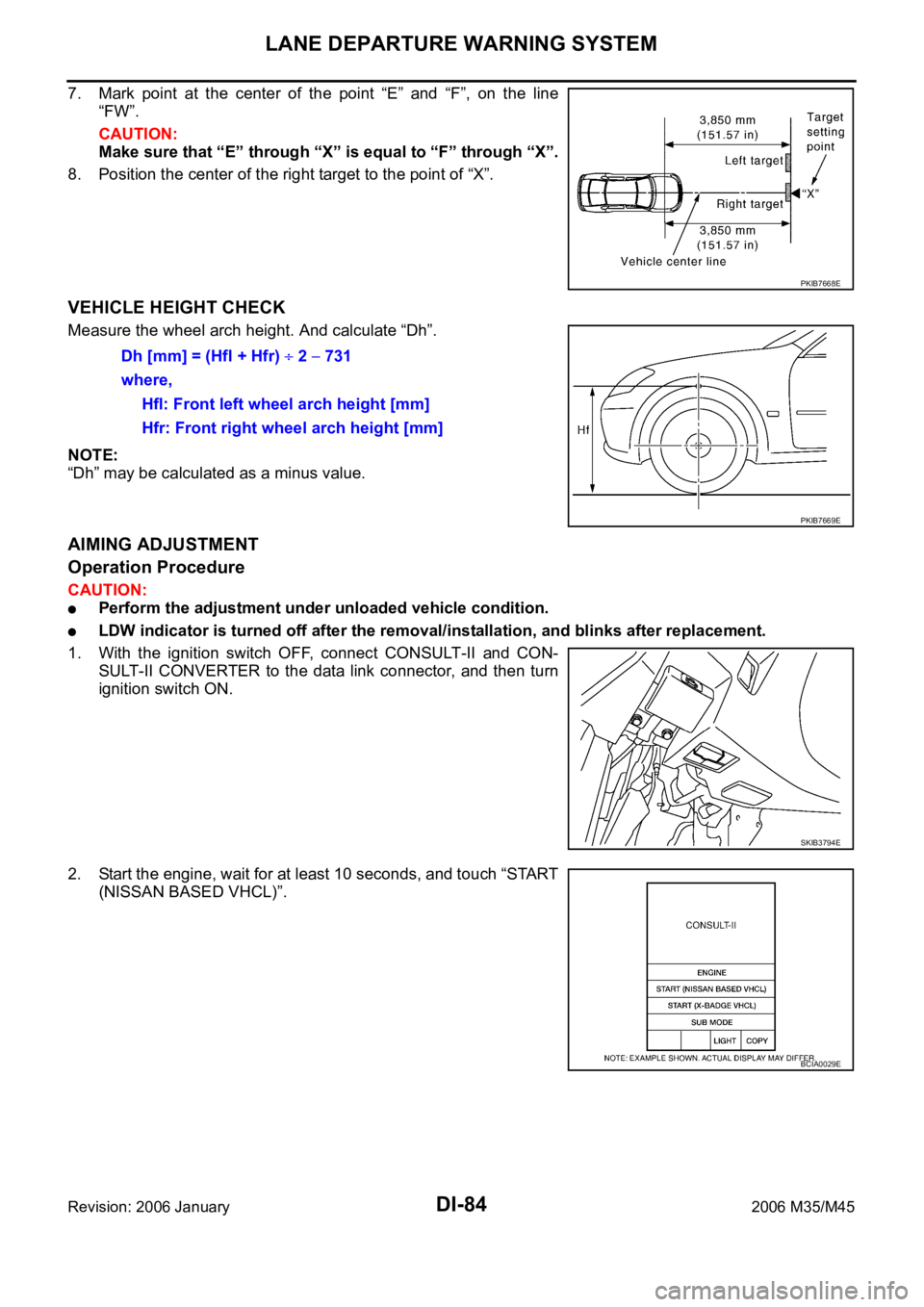
7. Mark point at the center of the point “E” and “F”, on the line
“FW”.
CAUTION:
Make sure that “E” through “X” is equal to “F” through “X”.
8. Position the center of the right target to the point of “X”.
VEHICLE HEIGHT CHECK
Measure the wheel arch height. And calculate “Dh”.
NOTE:
“Dh” may be calculated as a minus value.
AIMING ADJUSTMENT
Operation Procedure
CAUTION:
Perform the adjustment under unloaded vehicle condition.
LDW indicator is turned off after the removal/installation, and blinks after replacement.
1. With the ignition switch OFF, connect CONSULT-II and CON-
SULT-II CONVERTER to the data link connector, and then turn
ignition switch ON.
2. Start the engine, wait for at least 10 seconds, and touch “START
(NISSAN BASED VHCL)”.
PKIB7668E
Dh [mm] = (Hfl + Hfr) 2 731
where,
Hfl: Front left wheel arch height [mm]
Hfr: Front right wheel arch height [mm]
PKIB7669E
SKIB3794E
BCIA0029E
Page 3066 of 5621
EM-3
C
D
E
F
G
H
I
J
K
L
M
EMA
Revision: 2006 January2006 M35/M45 ANCE ................................................................146
MAIN BEARING OIL CLEARANCE ..................147
MAIN BEARING CRUSH HEIGHT ....................148
CONNECTING ROD BEARING CRUSH
HEIGHT .............................................................148
MAIN BEARING CAP BOLT OUTER DIAMETER .148
CONNECTING ROD BOLT OUTER DIAMETER .149
DRIVE PLATE ...................................................149
OIL JET .............................................................149
OIL JET RELIEF VALVE ...................................149
SERVICE DATA AND SPECIFICATIONS (SDS) ....150
Standard and Limit ...............................................150
GENERAL SPECIFICATIONS ..........................150
DRIVE BELT .....................................................151
INTAKE MANIFOLD COLLECTOR, INTAKE
MANIFOLD AND EXHAUST MANIFOLD .........151
SPARK PLUG ...................................................151
CAMSHAFT AND CAMSHAFT BEARING ........152
CYLINDER HEAD .............................................154
CYLINDER BLOCK ...........................................157
PISTON, PISTON RING AND PISTON PIN ......158
CONNECTING ROD .........................................159
CRANKSHAFT ..................................................160
MAIN BEARING ................................................161
CONNECTING ROD BEARING ........................162
VK45DE
PRECAUTIONS ......................................................163
Precautions for Procedures without Cowl Top Cover .163
Precautions Necessary for Steering Wheel Rotation
After Battery Disconnect ......................................163
OPERATION PROCEDURE .............................163
Precautions for Drain Engine Coolant and Engine
Oil .........................................................................163
Precautions for Disconnecting Fuel Piping ..........163
Precautions for Removal and Disassembly .........163
Precautions for Inspection, Repair and Replace-
ment .....................................................................164
Precautions for Assembly and Installation ...........164
Parts Requiring Angle Tightening .........................164
Precautions for Liquid Gasket ..............................164
REMOVAL OF LIQUID GASKET SEALING ......164
LIQUID GASKET APPLICATION PROCEDURE .165
PREPARATION .......................................................166
Special Service Tools ...........................................166
Commercial Service Tools ....................................169
NOISE, VIBRATION AND HARSHNESS (NVH)
TROUBLESHOOTING ............................................171
NVH Troubleshooting — Engine Noise ................171
Use the Chart Below to Help You Find the Cause
of the Symptom. ...................................................172
ENGINE ROOM COVER ........................................173
Components .........................................................173
Removal and Installation ......................................173
REMOVAL ........................................................
.173
INSTALLATION .................................................173DRIVE BELTS .........................................................174
Components .........................................................174
Checking Drive Belts ............................................174
Tension Adjustment .............................................
.174
Removal and Installation ......................................174
REMOVAL ........................................................
.174
INSTALLATION .................................................175
Components .........................................................176
Drive Belt Auto Tensioner and Idler Pulley ...........176
REMOVAL ........................................................
.176
INSTALLATION .................................................176
AIR CLEANER AND AIR DUCT .............................177
Components .........................................................177
Removal and Installation ......................................177
REMOVAL ........................................................
.177
INSPECTION AFTER REMOVAL .....................178
INSTALLATION .................................................178
Changing Air Cleaner Filter ..................................178
REMOVAL ........................................................
.178
INSTALLATION .................................................178
INTAKE MANIFOLD ..............................................
.179
Components .........................................................179
Removal and Installation ......................................180
REMOVAL ........................................................
.180
INSPECTION AFTER REMOVAL .....................182
INSTALLATION .................................................182
INSPECTION AFTER INSTALLATION ..............182
EXHAUST MANIFOLD AND THREE WAY CATA-
LYST ........................................................................183
Components .........................................................183
Removal and Installation ......................................183
REMOVAL ........................................................
.183
INSPECTION AFTER REMOVAL .....................185
INSTALLATION .................................................185
OIL PAN AND OIL STRAINER ...............................187
Components .........................................................187
Removal and Installation ......................................187
REMOVAL ........................................................
.187
INSPECTION AFTER REMOVAL .....................188
INSTALLATION .................................................188
INSPECTION AFTER INSTALLATION ..............189
IGNITION COIL .......................................................190
Components .........................................................190
Removal and Installation ......................................190
REMOVAL ........................................................
.190
INSTALLATION .................................................190
SPARK PLUG (PLATINUM-TIPPED TYPE) ...........191
Components .........................................................191
Removal and Installation ......................................191
REMOVAL ........................................................
.191
INSPECTION AFTER REMOVAL .....................191
INSTALLATION .................................................192
FUEL INJECTOR AND FUEL TUBE ......................193
Components .........................................................193
Removal and Installation ......................................193
REMOVAL ........................................................
.193
INSTALLATION .................................................195
INSPECTION AFTER INSTALLATION ..............197
Page 3067 of 5621
EM-4Revision: 2006 January2006 M35/M45 ROCKER COVER ...................................................199
Components .........................................................199
Removal and Installation ......................................199
REMOVAL ........................................................
.199
INSTALLATION ..................................................201
TIMING CHAIN ........................................................203
Components .........................................................203
Removal and Installation ......................................204
REMOVAL ........................................................
.204
INSPECTION AFTER REMOVAL ......................208
INSTALLATION ..................................................208
INSPECTION AFTER INSTALLATION ..............214
CAMSHAFT .............................................................215
Components .........................................................215
Removal and Installation ......................................215
REMOVAL ........................................................
.215
INSPECTION AFTER REMOVAL ......................216
INSTALLATION ..................................................219
INSPECTION AFTER INSTALLATION ..............221
INSPECTION AFTER INSTALLATION ..............222
Valve Clearance ....................................................222
INSPECTION .....................................................222
ADJUSTMENT ..................................................225
OIL SEAL ................................................................229
Removal and Installation of Valve Oil Seal ...........229
REMOVAL ........................................................
.229
INSTALLATION ..................................................229
Removal and Installation of Front Oil Seal ...........230
REMOVAL ........................................................
.230
INSTALLATION ..................................................230
Removal and Installation of Rear Oil Seal ............231
REMOVAL ........................................................
.231
INSTALLATION ..................................................231
CYLINDER HEAD .................................................. .233
On-Vehicle Service ...............................................233
CHECKING COMPRESSION PRESSURE .......233
Components .........................................................234
Removal and Installation ......................................234
REMOVAL ........................................................
.234
INSPECTION AFTER REMOVAL ......................235
INSTALLATION ..................................................235
Disassembly and Assembly ..................................237
COMPONENTS .................................................237
DISASSEMBLY .................................................237
ASSEMBLY ......................................................
.238
Inspection after Disassembly ................................239
VALVE DIMENSIONS ........................................239
VALVE GUIDE CLEARANCE ............................240
VALVE GUIDE REPLACEMENT .......................240
VALVE SEAT CONTACT ...................................242
VALVE SEAT REPLACEMENT .........................242
VALVE SPRING SQUARENESS .......................243
VALVE SPRING DIMENSIONS AND VALVE
SPRING PRESSURE LOAD .............................243ENGINE ASSEMBLY ...............................................244
Components ..........................................................244
Removal and Installation .......................................244
REMOVAL ..........................................................245
INSTALLATION ..................................................247
INSPECTION AFTER INSTALLATION ..............247
CYLINDER BLOCK .................................................249
Components ..........................................................249
Disassembly and Assembly ..................................250
DISASSEMBLY ..................................................250
ASSEMBLY ........................................................254
How to Select Piston and Bearing ........................259
DESCRIPTION ..................................................259
HOW TO SELECT PISTON ...............................260
HOW TO SELECT CONNECTING ROD BEAR-
ING .....................................................................261
HOW TO SELECT MAIN BEARING ..................262
Inspection after Disassembly ................................266
CRANKSHAFT END PLAY ................................266
CONNECTING ROD SIDE CLEARANCE .........266
PISTON TO PISTON PIN OIL CLEARANCE .....266
PISTON RING SIDE CLEARANCE ...................267
PISTON RING END GAP ..................................267
CONNECTING ROD BEND AND TORSION .....268
CONNECTING ROD BIG END DIAMETER ......268
CONNECTING ROD BUSHING OIL CLEAR-
ANCE .................................................................268
CYLINDER BLOCK DISTORTION ....................269
MAIN BEARING HOUSING INNER DIAMETER .270
PISTON TO CYLINDER BORE CLEARANCE ..270
CRANKSHAFT MAIN JOURNAL DIAMETER ...271
CRANKSHAFT PIN JOURNAL DIAMETER ......272
CRANKSHAFT OUT-OF-ROUND AND TAPER .272
CRANKSHAFT RUNOUT ..................................272
CONNECTING ROD BEARING OIL CLEAR-
ANCE .................................................................273
MAIN BEARING OIL CLEARANCE ...................274
CRUSH HEIGHT OF MAIN BEARING ..............275
CRUSH HEIGHT OF CONNECTING ROD
BEARING ...........................................................275
DRIVE PLATE ....................................................275
SERVICE DATA AND SPECIFICATIONS (SDS) ....276
Standard and Limit ................................................276
GENERAL SPECIFICATIONS ...........................276
DRIVE BELTS ....................................................276
INTAKE MANIFOLD AND EXHAUST MANI-
FOLD .................................................................276
SPARK PLUG ....................................................277
CAMSHAFT AND CAMSHAFT BEARING .........277
CYLINDER HEAD ..............................................279
CYLINDER BLOCK ............................................282
PISTON, PISTON RING AND PISTON PIN ......283
CONNECTING ROD ..........................................284
CRANKSHAFT ...................................................285
MAIN BEARING .................................................287
CONNECTING ROD BEARING .........................288