Page 1143 of 5621

BL-204
TRUNK LID
Revision: 2006 January2006 M35/M45
Loosen the striker mounting bolts.
Lift up the trunk lid approx. 100 - 150 mm (3.94 - 5.91 in) height then close it lightly and make sure it
engaged firmly with the trunk lid closed.
Check the clearance and evenness.
Finally tighten the trunk lid striker.
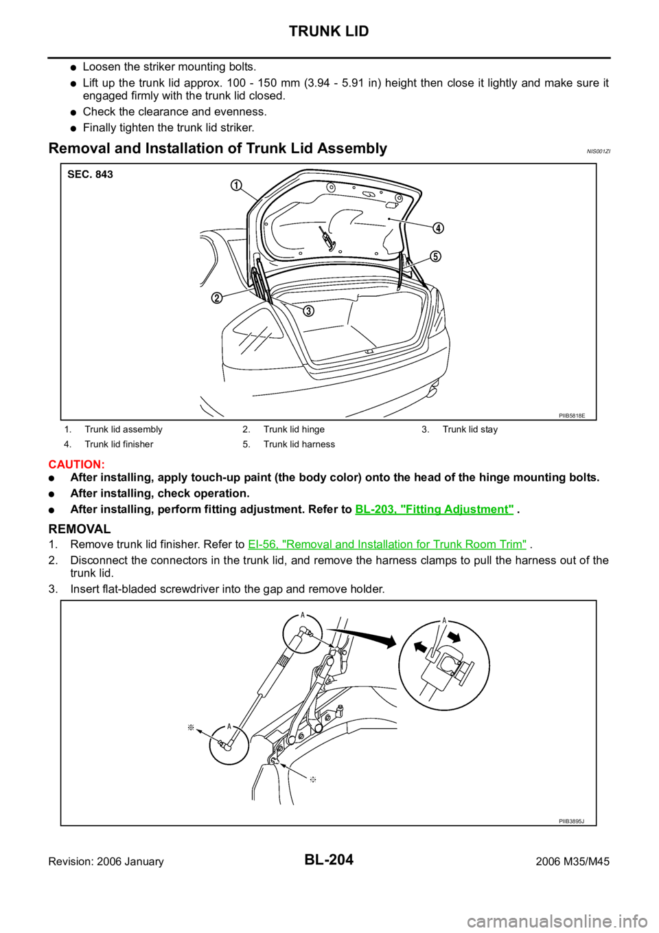
Removal and Installation of Trunk Lid AssemblyNIS001ZI
CAUTION:
After installing, apply touch-up paint (the body color) onto the head of the hinge mounting bolts.
After installing, check operation.
After installing, perform fitting adjustment. Refer to BL-203, "Fitting Adjustment" .
REMOVAL
1. Remove trunk lid finisher. Refer to EI-56, "Removal and Installation for Trunk Room Trim" .
2. Disconnect the connectors in the trunk lid, and remove the harness clamps to pull the harness out of the
trunk lid.
3. Insert flat-bladed screwdriver into the gap and remove holder.
1. Trunk lid assembly 2. Trunk lid hinge 3. Trunk lid stay
4. Trunk lid finisher 5. Trunk lid harness
PIIB5818E
PIIB3895J
Page 1145 of 5621
BL-206
TRUNK LID
Revision: 2006 January2006 M35/M45
Removal and Installation of Trunk Lid LockNIS001ZK
REMOVAL
1. Remove the trunk lid finisher. Refer to EI-56, "Removal and Installation for Trunk Room Trim" .
2. Remove the trunk lid emergency opener lever.
3. Disconnect the trunk lid opener cable.
4. Disconnect the trunk lid.
5. Remove the mounting bolts, and remove the trunk lid lock.
INSTALLATION
1. Install in the reverse order of removal.
2. After installing, close the trunk lid height. Perform the lock and surface height adjustment. Refer to BL-
203, "Fitting Adjustment" .
3. After installing, check the operation.
1. Trunk lid lock 2. Trunk lid opener cable 3. Trunk lid key cylinder
4. Trunk lid opener switch 5. Trunk lid emergency opener lever
PIIB5819E
PIIB5820E
Page 1146 of 5621
TRUNK LID
BL-207
C
D
E
F
G
H
J
K
L
MA
B
BL
Revision: 2006 January2006 M35/M45
Removal and Installation of Trunk Lid StrikerNIS001ZL
REMOVAL
1. Remove the trunk rear plate and trunk rear finisher. Refer to EI-
56, "Removal and Installation for Trunk Room Trim" .
2. Remove the mounting bolts, and remove the striker from the
trunk lock support.
INSTALLATION
1. Install in the reverse order of removal.
2. After installing, close the trunk lid height. Perform the lock and surface height adjustment. Refer to BL-
203, "Fitting Adjustment" .
3. After installing, check the operation.
PIIB3914J
Page 1281 of 5621
BR-6
BRAKE PEDAL
Revision: 2006 January2006 M35/M45
BRAKE PEDALPFP:46501
Inspection and AdjustmentNFS000OS
Play and clearance inspection between brake pedal and floor panel with pedal depressed.
Check brake pedal play.
Check brake pedal height from dash lower panel (1).
Adjust height referring to the following specifications.
SFIA2743J
H1Brake pedal height (from dash lower panel top surface) 157 167 mm (6.18 6.57 in)
H
2Depressed brake pedal height
[under a force of 490 N (50 kg, 110 lb) with engine running]90 mm (3.54 in) or more
CClearance between threaded end of the stop lamp switch/brake switch
(2) and bracket (3)0.74
1.96 mm (0.0291 0.0772 in)
A Pedal play 3
11 mm (0.12 0.43 in)
Page 1282 of 5621

BRAKE PEDAL
BR-7
C
D
E
G
H
I
J
K
L
MA
B
BR
Revision: 2006 January2006 M35/M45
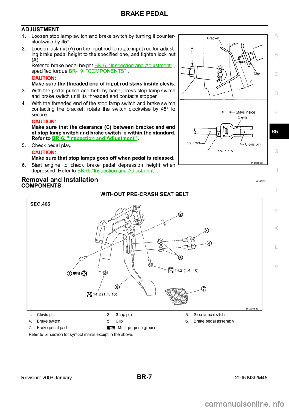
ADJUSTMENT
1. Loosen stop lamp switch and brake switch by turning it counter-
clockwise by 45
.
2. Loosen lock nut (A) on the input rod to rotate input rod for adjust-
ing brake pedal height to the specified one, and tighten lock nut
(A).
Refer to brake pedal height BR-6, "
Inspection and Adjustment" ,
specified torque BR-19, "
COMPONENTS" .
CAUTION:
Make sure the threaded end of input rod stays inside clevis.
3. With the pedal pulled and held by hand, press stop lamp switch
and brake switch until its threaded end contacts stopper.
4. With the threaded end of the stop lamp switch and brake switch
contacting the bracket, rotate the switch clockwise by 45
to
secure.
CAUTION:
Make sure that the clearance (C) between bracket and end
of stop lamp switch and brake switch is within the standard.
Refer to BR-6, "
Inspection and Adjustment" .
5. Check pedal play.
CAUTION:
Make sure that stop lamps goes off when pedal is released.
6. Start engine to check brake pedal depression height when
depressed. Refer to BR-6, "
Inspection and Adjustment" .
Removal and InstallationNFS000OT
COMPONENTS
WITHOUT PRE-CRASH SEAT BELT
PFIA0436E
SFIA2951E
1. Clevis pin 2. Snap pin 3. Stop lamp switch
4. Brake switch 5. Clip 6. Brake pedal assembly
7. Brake pedal pad : Multi-purpose grease
Refer to GI section for symbol marks except in the above.
Page 1284 of 5621
BRAKE PEDAL
BR-9
C
D
E
G
H
I
J
K
L
MA
B
BR
Revision: 2006 January2006 M35/M45
INSTALLATION
Installation is the reverse order of removal. Tightening torques for brake pedal assembly mounting nuts and
bolt are referred to BR-7, "
COMPONENTS" . Tightening torque for lock nut is referred to BR-19, "COMPO-
NENTS" .
Adjust brake pedal height after installing brake pedal assembly to vehicle. Refer to BR-6, "Inspection and
Adjustment" .
CAUTION:
Do not reuse clevis pin.
Page 1295 of 5621
BR-20
BRAKE BOOSTER
Revision: 2006 January2006 M35/M45
4. Install brake pedal bracket mounting nuts and bolt, and tighten them to the specified torque. Refer to BR-
7, "COMPONENTS" .
5. Install vacuum hose into brake booster. Refer to BR-22, "
Removal and Installation" .
6. Install master cylinder to booster assembly. Refer to BR-15, "
Removal and Installation" .
7. Adjust the brake pedal height and the play of the brake pedal. Refer to BR-7, "
ADJUSTMENT" .
8. Tighten lock nut of input rod to the specified torque. Refer to BR-19, "
COMPONENTS" .
9. Connect front left brake tube to ABS actuator and electric unit (control unit). Refer to BR-12, "
Hydraulic
Circuit" .
10. Install cowl top. Refer to EI-18, "
Removal and Installation" .
11. Refill new brake fluid and bleed air. Refer to BR-11, "
Bleeding Brake System" .
Page 1310 of 5621

SERVICE DATA AND SPECIFICATIONS (SDS)
BR-35
C
D
E
G
H
I
J
K
L
MA
B
BR
Revision: 2006 January2006 M35/M45
SERVICE DATA AND SPECIFICATIONS (SDS)PFP:00030
General SpecificationsNFS000PL
Unit: mm (in)
Brake PedalNFS000PM
Brake BoosterNFS000PN
Va c u u m t y p e
Check ValveNFS000PO
Front Disc BrakeNFS000PP
Front brake Brake model CLZ31VD, CLZ31VB
Cylinder bore diameter 45 (1.772)
2
Pad length
width thickness 132 50 11 (5.20 1.969 0.433)
Rotor outer diameter
thickness 320 28 (12.60 1.10)
Rear brake Brake model AD14VF, AD14VE
Cylinder bore diameter 42.86 (1.687)
Pad length
width thickness 83.0 31.9 8.5 (3.268 1.256 0.335)
Rotor outer diameter
thickness 308 16 (12.13 0.63)
Master cylinder Cylinder bore diameter 25.4 (1)
Control valve Valve model Electric brake force distribution
Brake boosterBooster model N255
Diaphragm diameter 255 (10)
Recommended brake fluid DOT 3
Brake pedal height (from dash lower panel top surface) 157 167 mm (6.18 6.57 in)
Depressed pedal height
[under a force of 490 N (50 kg, 110 lb) with engine running]90 mm (3.54 in) or more
Clearance between threaded end of the stop lamp switch/brake switch
and bracket 0.74 - 1.96 mm (0.0291 - 0.0772 in)
Pedal play3 - 11 mm (0.12 - 0.43 in)
Input rod installation standard dimension 125 mm (4.92 in)
Vacuum leakage
[at vacuum of – 66.7 kPa (– 500 mmHg, – 19.69 inHg)]Within 1.3 kPa (10 mmHg, 0.39 inHg) of vacuum for 15 seconds
Brake modelCLZ31VD, CLZ31VB
Brake padStandard thickness 11.0 mm (0.433 in)
Repair limit thickness 2.0 mm (0.079 in)
Disc rotorStandard thickness 28.0 mm (1.102 in)
Wear limit 26.0 mm (1.024 in)
Thickness variation (measured at 8 positions) 0.015 mm (0.0006 in)
Runout limit (with it attached to the vehicle) 0.035 mm (0.0014 in)