Page 5099 of 5621

RSU-18
SERVICE DATA
Revision: 2006 January2006 M35/M45
SERVICE DATAPFP:00030
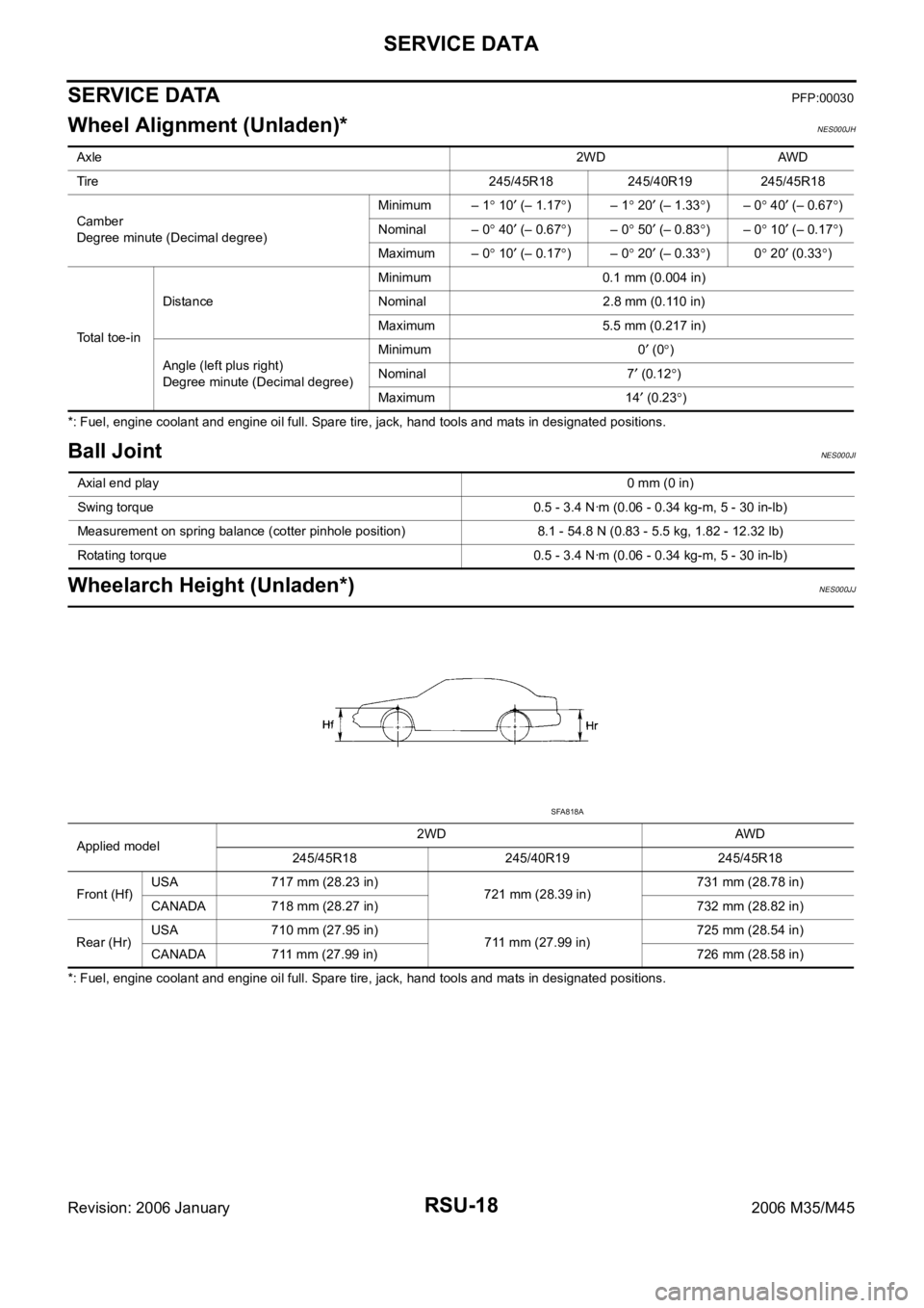
Wheel Alignment (Unladen)*NES000JH
*: Fuel, engine coolant and engine oil full. Spare tire, jack, hand tools and mats in designated positions.
Ball JointNES000JI
Wheelarch Height (Unladen*)NES000JJ
*: Fuel, engine coolant and engine oil full. Spare tire, jack, hand tools and mats in designated positions. Axle2WD AWD
Tire 245/45R18 245/40R19 245/45R18
Camber
Degree minute (Decimal degree)Minimum – 1
10 (– 1.17)– 1 20 (– 1.33)– 0 40 (– 0.67)
Nominal – 0
40 (– 0.67)– 0 50 (– 0.83)– 0 10 (– 0.17)
Maximum – 0
10 (– 0.17)– 0 20 (– 0.33)0 20 (0.33)
Total toe-inDistanceMinimum 0.1 mm (0.004 in)
Nominal 2.8 mm (0.110 in)
Maximum 5.5 mm (0.217 in)
Angle (left plus right)
Degree minute (Decimal degree)Minimum 0
(0)
Nominal 7
(0.12)
Maximum 14
(0.23)
Axial end play0 mm (0 in)
Swing torque 0.5 - 3.4 Nꞏm (0.06 - 0.34 kg-m, 5 - 30 in-lb)
Measurement on spring balance (cotter pinhole position) 8.1 - 54.8 N (0.83 - 5.5 kg, 1.82 - 12.32 lb)
Rotating torque 0.5 - 3.4 Nꞏm (0.06 - 0.34 kg-m, 5 - 30 in-lb)
Applied model2WD AWD
245/45R18 245/40R19 245/45R18
Front (Hf)USA 717 mm (28.23 in)
721 mm (28.39 in)731 mm (28.78 in)
CANADA 718 mm (28.27 in) 732 mm (28.82 in)
Rear (Hr)USA 710 mm (27.95 in)
711 mm (27.99 in)725 mm (28.54 in)
CANADA 711 mm (27.99 in) 726 mm (28.58 in)
SFA818A
Page 5132 of 5621

SEAT BELTS
SB-33
C
D
E
F
G
I
J
K
L
MA
B
SB
Revision: 2006 January2006 M35/M45
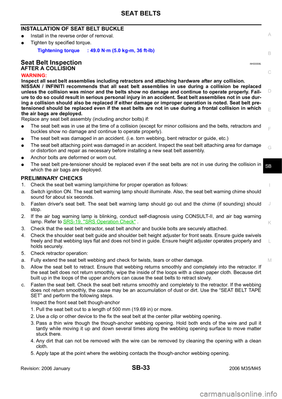
INSTALLATION OF SEAT BELT BUCKLE
Install in the reverse order of removal.
Tighten by specified torque.
Seat Belt InspectionNHS0008L
AFTER A COLLISION
WAR NING :
Inspect all seat belt assemblies including retractors and attaching hardware after any collision.
NISSAN / INFINITI recommends that all seat belt assemblies in use during a collision be replaced
unless the collision was minor and the belts show no damage and continue to operate properly. Fail-
ure to do so could result in serious personal injury in an accident. Seat belt assemblies not in use dur-
ing a collision should also be replaced if either damage or improper operation is noted. Seat belt pre-
tensioned should be replaced even if the seat belts are not in use during a frontal collision in which
the air bags are deployed.
Replace any seat belt assembly (including anchor bolts) if:
The seat belt was in use at the time of a collision (except for minor collisions and the belts, retractors and
buckles show no damage and continue to operate properly).
The seat belt was damaged in an accident. (i.e. torn webbing, bent retractor or guide, etc.)
The seat belt attaching point was damaged in an accident. Inspect the seat belt attaching area for damage
or distortion and repair as necessary before installing a new seat belt assembly.
Anchor bolts are deformed or worn out.
The seat belt pre-tensioner should be replaced even if the seat belts are not in use during the collision in
which the air bags are deployed.
PRELIMINARY CHECKS
1. Check the seat belt warning lamp/chime for proper operation as follows:
a. Switch ignition ON. The seat belt warning lamp should illuminate. Also, the seat belt warning chime should
sound for about six seconds.
b. Fasten driver's seat belt. The seat belt warning lamp should go out and the chime (if sounding) should
stop.
2. If the air bag warning lamp is blinking, conduct self-diagnosis using CONSULT-II, and air bag warning
lamp. Refer to SRS-19, "
SRS Operation Check" .
3. Check that the seat belt retractor, seat belt anchor and buckle bolts are securely attached.
4. Check the shoulder seat belt guide and shoulder belt height adjuster for front seats. Ensure guide swivels
freely and that webbing lays flat and does not bind in guide. Ensure height adjuster operates properly and
holds securely.
5. Check retractor operation:
a. Fully extend the seat belt webbing and check for twists, tears or other damage.
b. Allow the seat belt to retract. Ensure that webbing returns smoothly and completely into the retractor. If
the seat belt does not return smoothly, wipe the inside of the loops with a clean paper cloth. Because dirt
built up in the loops of the upper anchors can cause the seat belts to retract slowly.
c. Fasten the seat belt. Check the seat belt returns smoothly and completely to the retractor. If the webbing
does not return smoothly, the cause may be an accumulation of dust or dirt. Use the “SEAT BELT TAPE
SET” and perform the following steps.
Inspect the front seat belt though-anchor
1. Pull the seat belt out to a length of 500 mm (19.69 in) or more.
2. Use a clip or other device to the fix the seat belt at the center pillar webbing opening.
3. Pass a thin wire though the though-anchor webbing opening. Hold both ends of the wire and pull it
tantly while moving it up and down several times along the webbing opening surface to move matter
stuck there.
4. Any dirt that can not be removed with the wire can be removed by cleaning the opening with a clean
cloth.
5. Apply tape at the point where the webbing contacts the though-anchor webbing opening. Tightening torque : 49.0 Nꞏm (5.0 kg-m, 36 ft-lb)
Page 5611 of 5621

WW-44
FRONT WIPER AND WASHER SYSTEM
Revision: 2006 January2006 M35/M45
DISASSEMBLY
1. Remove wiper linkage from wiper motor and motor frame.
2. Remove wiper motor mounting bolts (3), and remove wiper motor from wiper frame.
CAUTION:
Be careful not to bend linkage and not to damage the resin part of ball joint when removing wiper link-
age.
ASSEMBLY
1. Connect wiper motor connector. Turn wiper switch ON to operate wiper motor, and then turn wiper switch
OFF (auto stop).
2. Disconnect wiper motor connector.
3. Install wiper motor to wiper frame.
4. Install wiper linkage to wiper frame and wiper motor.
CAUTION:
Never drop the wiper motor or cause it to contact other parts.
Check grease conditions of the motor arm and wiper linkage joint (at retainer). Apply grease if
necessary.
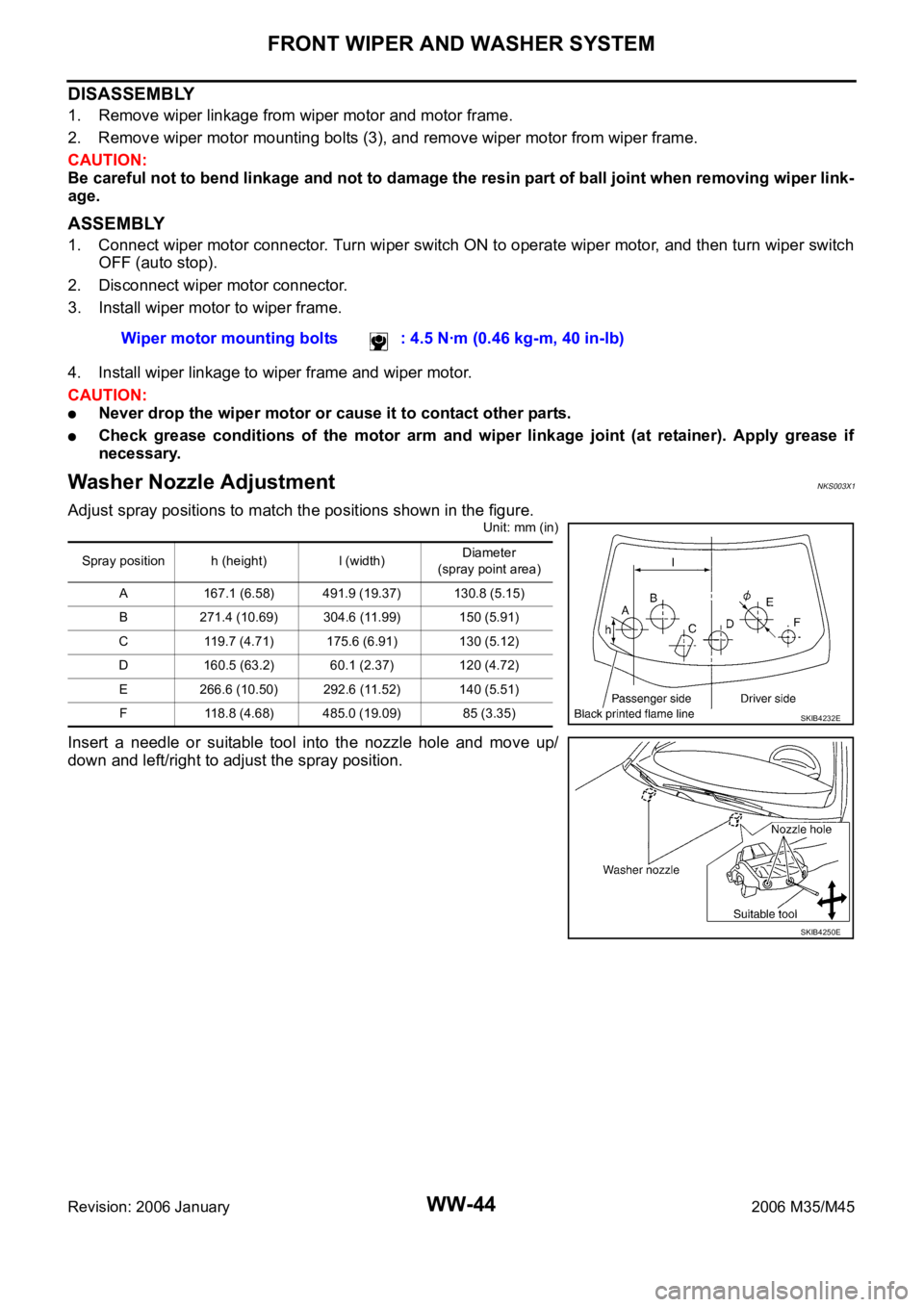
Washer Nozzle AdjustmentNKS003X1
Adjust spray positions to match the positions shown in the figure.
Unit: mm (in)
Insert a needle or suitable tool into the nozzle hole and move up/
down and left/right to adjust the spray position.Wiper motor mounting bolts : 4.5 Nꞏm (0.46 kg-m, 40 in-lb)
Spray position h (height) l (width)Diameter
(spray point area)
A 167.1 (6.58) 491.9 (19.37) 130.8 (5.15)
B 271.4 (10.69) 304.6 (11.99) 150 (5.91)
C 119.7 (4.71) 175.6 (6.91) 130 (5.12)
D 160.5 (63.2) 60.1 (2.37) 120 (4.72)
E 266.6 (10.50) 292.6 (11.52) 140 (5.51)
F 118.8 (4.68) 485.0 (19.09) 85 (3.35)
SKIB4232E
SKIB4250E