2006 INFINITI M35 height
[x] Cancel search: heightPage 4611 of 5621
LT-184
ACTIVE AFS
Revision: 2006 January2006 M35/M45
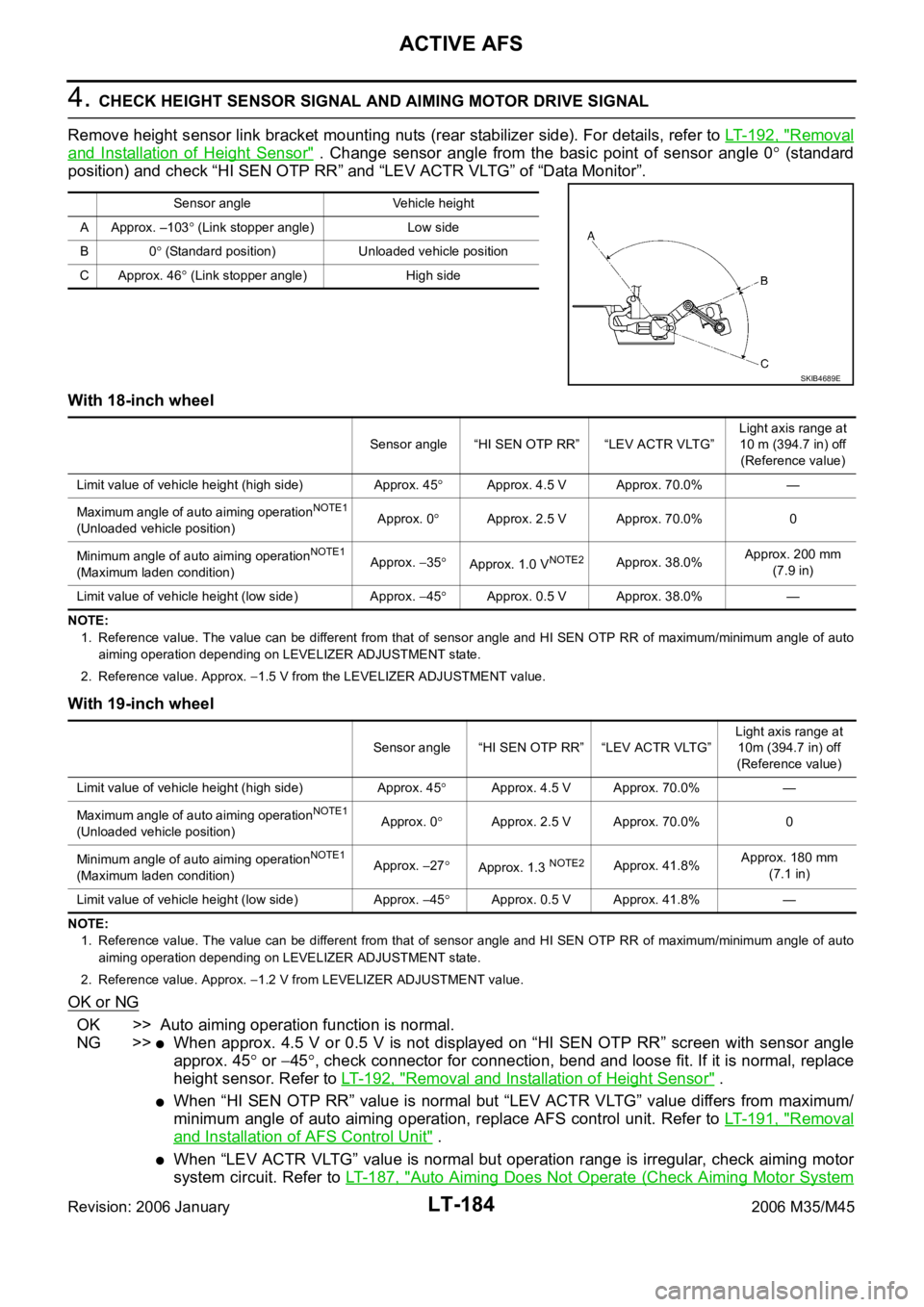
4. CHECK HEIGHT SENSOR SIGNAL AND AIMING MOTOR DRIVE SIGNAL
Remove height sensor link bracket mounting nuts (rear stabilizer side). For details, refer to LT- 1 9 2 , "
Removal
and Installation of Height Sensor" . Change sensor angle from the basic point of sensor angle 0 (standard
position) and check “HI SEN OTP RR” and “LEV ACTR VLTG” of “Data Monitor”.
With 18-inch wheel
NOTE:
1. Reference value. The value can be different from that of sensor angle and HI SEN OTP RR of maximum/minimum angle of auto
aiming operation depending on LEVELIZER ADJUSTMENT state.
2. Reference value. Approx.
1.5 V from the LEVELIZER ADJUSTMENT value.
With 19-inch wheel
NOTE:
1. Reference value. The value can be different from that of sensor angle and HI SEN OTP RR of maximum/minimum angle of auto
aiming operation depending on LEVELIZER ADJUSTMENT state.
2. Reference value. Approx.
1.2 V from LEVELIZER ADJUSTMENT value.
OK or NG
OK >> Auto aiming operation function is normal.
NG >>
When approx. 4.5 V or 0.5 V is not displayed on “HI SEN OTP RR” screen with sensor angle
approx. 45
or 45, check connector for connection, bend and loose fit. If it is normal, replace
height sensor. Refer to LT- 1 9 2 , "
Removal and Installation of Height Sensor" .
When “HI SEN OTP RR” value is normal but “LEV ACTR VLTG” value differs from maximum/
minimum angle of auto aiming operation, replace AFS control unit. Refer to LT- 1 9 1 , "
Removal
and Installation of AFS Control Unit" .
When “LEV ACTR VLTG” value is normal but operation range is irregular, check aiming motor
system circuit. Refer to LT- 1 8 7 , "
Auto Aiming Does Not Operate (Check Aiming Motor System
Sensor angle Vehicle height
A Approx. –103
(Link stopper angle) Low side
B0
(Standard position) Unloaded vehicle position
C Approx. 46
(Link stopper angle) High side
SKIB4689E
Sensor angle “HI SEN OTP RR” “LEV ACTR VLTG”Light axis range at
10 m (394.7 in) off
(Reference value)
Limit value of vehicle height (high side) Approx. 45
Approx. 4.5 V Approx. 70.0% —
Maximum angle of auto aiming operation
NOTE1
(Unloaded vehicle position)Approx. 0Approx. 2.5 V Approx. 70.0% 0
Minimum angle of auto aiming operation
NOTE1
(Maximum laden condition)Approx. 35Approx. 1.0 VNOTE2Approx. 38.0%Approx. 200 mm
(7.9 in)
Limit value of vehicle height (low side) Approx.
45Approx. 0.5 V Approx. 38.0% —
Sensor angle “HI SEN OTP RR” “LEV ACTR VLTG”Light axis range at
10m (394.7 in) off
(Reference value)
Limit value of vehicle height (high side) Approx. 45
Approx. 4.5 V Approx. 70.0% —
Maximum angle of auto aiming operation
NOTE1
(Unloaded vehicle position)Approx. 0Approx. 2.5 V Approx. 70.0% 0
Minimum angle of auto aiming operation
NOTE1
(Maximum laden condition)Approx. 27Approx. 1.3 NOTE2Approx. 41.8%Approx. 180 mm
(7.1 in)
Limit value of vehicle height (low side) Approx.
45Approx. 0.5 V Approx. 41.8% —
Page 4619 of 5621
LT-192
ACTIVE AFS
Revision: 2006 January2006 M35/M45
Removal and Installation of Height SensorNKS003R1
REMOVAL
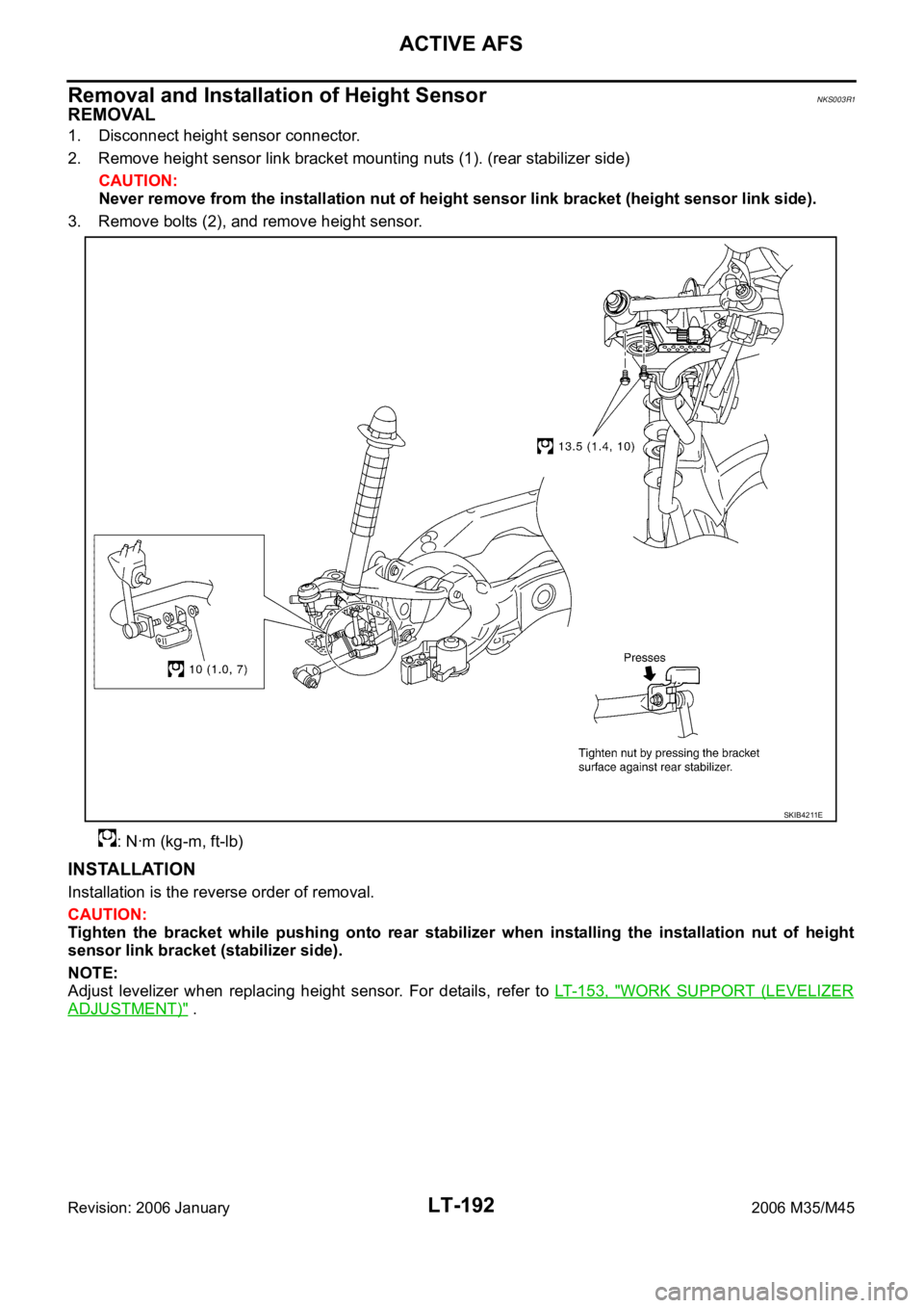
1. Disconnect height sensor connector.
2. Remove height sensor link bracket mounting nuts (1). (rear stabilizer side)
CAUTION:
Never remove from the installation nut of height sensor link bracket (height sensor link side).
3. Remove bolts (2), and remove height sensor.
: Nꞏm (kg-m, ft-lb)
INSTALLATION
Installation is the reverse order of removal.
CAUTION:
Tighten the bracket while pushing onto rear stabilizer when installing the installation nut of height
sensor link bracket (stabilizer side).
NOTE:
Adjust levelizer when replacing height sensor. For details, refer to LT- 1 5 3 , "
WORK SUPPORT (LEVELIZER
ADJUSTMENT)" .
SKIB4211E
Page 4974 of 5621
POWER STEERING GEAR
PS-21
C
D
E
F
H
I
J
K
L
MA
B
PS
Revision: 2006 January2006 M35/M45
DISASSEMBLY
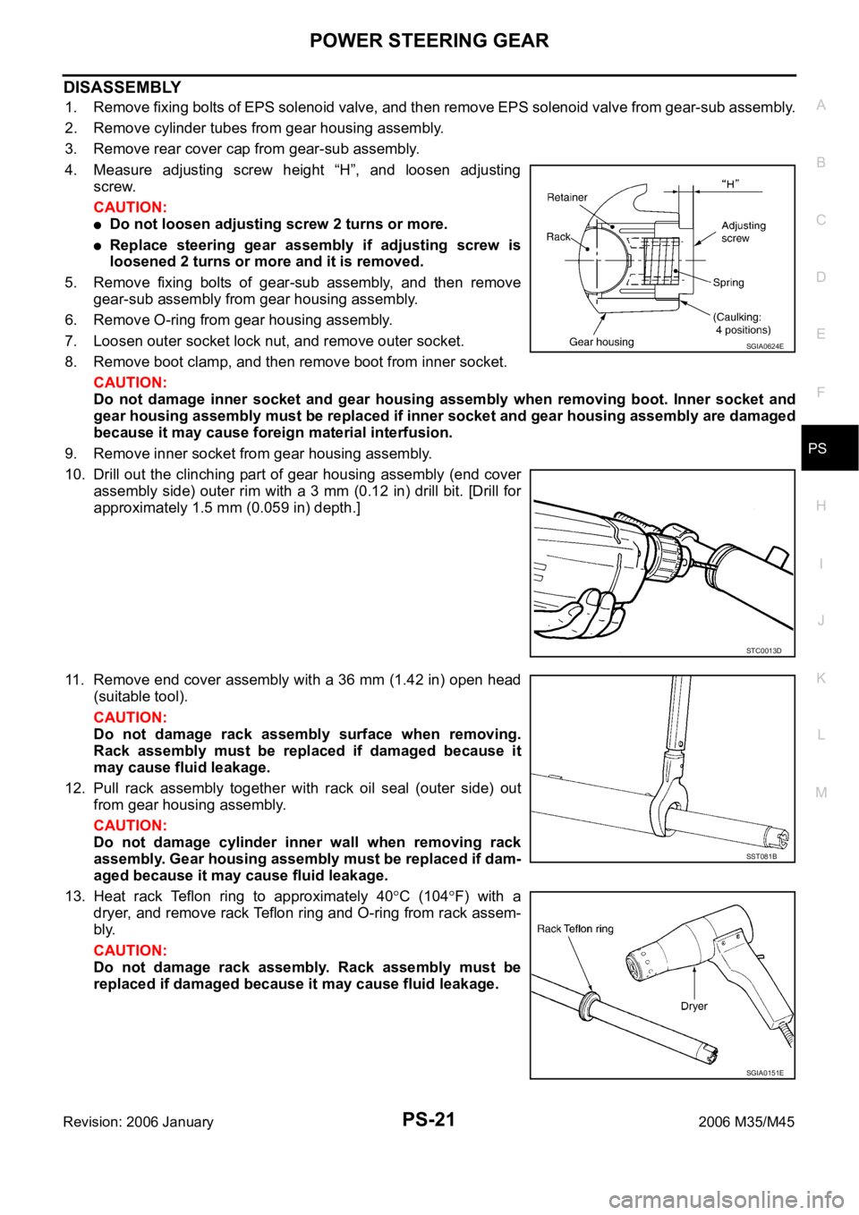
1. Remove fixing bolts of EPS solenoid valve, and then remove EPS solenoid valve from gear-sub assembly.
2. Remove cylinder tubes from gear housing assembly.
3. Remove rear cover cap from gear-sub assembly.
4. Measure adjusting screw height “H”, and loosen adjusting
screw.
CAUTION:
Do not loosen adjusting screw 2 turns or more.
Replace steering gear assembly if adjusting screw is
loosened 2 turns or more and it is removed.
5. Remove fixing bolts of gear-sub assembly, and then remove
gear-sub assembly from gear housing assembly.
6. Remove O-ring from gear housing assembly.
7. Loosen outer socket lock nut, and remove outer socket.
8. Remove boot clamp, and then remove boot from inner socket.
CAUTION:
Do not damage inner socket and gear housing assembly when removing boot. Inner socket and
gear housing assembly must be replaced if inner socket and gear housing assembly are damaged
because it may cause foreign material interfusion.
9. Remove inner socket from gear housing assembly.
10. Drill out the clinching part of gear housing assembly (end cover
assembly side) outer rim with a 3 mm (0.12 in) drill bit. [Drill for
approximately 1.5 mm (0.059 in) depth.]
11. Remove end cover assembly with a 36 mm (1.42 in) open head
(suitable tool).
CAUTION:
Do not damage rack assembly surface when removing.
Rack assembly must be replaced if damaged because it
may cause fluid leakage.
12. Pull rack assembly together with rack oil seal (outer side) out
from gear housing assembly.
CAUTION:
Do not damage cylinder inner wall when removing rack
assembly. Gear housing assembly must be replaced if dam-
aged because it may cause fluid leakage.
13. Heat rack Teflon ring to approximately 40
C (104F) with a
dryer, and remove rack Teflon ring and O-ring from rack assem-
bly.
CAUTION:
Do not damage rack assembly. Rack assembly must be
replaced if damaged because it may cause fluid leakage.
SGIA0624E
STC0013D
SST081B
SGIA0151E
Page 4979 of 5621
PS-26
POWER STEERING GEAR
Revision: 2006 January2006 M35/M45
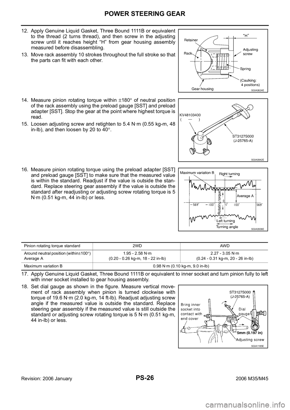
1 2 . A p p l y G e n u i n e L i q u i d G a s k e t , T h r e e B o u n d 1111 B o r e q u i v a l e n t
to the thread (2 turns thread), and then screw in the adjusting
screw until it reaches height “H” from gear housing assembly
measured before disassembling.
13. Move rack assembly 10 strokes throughout the full stroke so that
the parts can fit with each other.
14. Measure pinion rotating torque within
180 of neutral position
of the rack assembly using the preload gauge [SST] and preload
adapter [SST]. Stop the gear at the point where highest torque is
read.
15. Loosen adjusting screw and retighten to 5.4 Nꞏm (0.55 kg-m, 48
in-lb), and then loosen by 20 to 40
.
16. Measure pinion rotating torque using the preload adapter [SST]
and preload gauge [SST] to make sure that the measured value
is within the standard. Readjust if the value is outside the stan-
dard. Replace steering gear assembly if the value is outside the
standard after readjusting or adjusting screw rotating torque is 5
Nꞏm (0.51 kg-m, 44 in-lb) or less.
17. Apply Genuine Liquid Gasket, Three Bound 1111B or equivalent to inner socket and turn pinion fully to left
with inner socket installed to gear housing assembly.
18. Set dial gauge as shown in the figure. Measure vertical move-
ment of rack assembly when pinion is turned clockwise with
torque of 19.6 Nꞏm (2.0 kg-m, 14 ft-lb). Readjust adjusting screw
angle if the measured value is outside the standard. Replace
steering gear assembly if the measured value is still outside the
standard or adjusting screw rotating torque is 5 Nꞏm (0.51 kg-m,
44 in-lb) or less.
SGIA0624E
SGIA0942E
SGIA0936E
Pinion rotating torque standard 2WD AWD
Around neutral position (within
100)
Average A1.95 - 2.58 Nꞏm
(0.20 - 0.26 kg-m, 18 - 22 in-lb)2.27 - 3.05 Nꞏm
(0.24 - 0.31 kg-m, 20 - 26 in-lb)
Maximum variation B 0.98 Nꞏm (0.10 kg-m, 9.0 in-lb)
SGIA1185E
Page 5048 of 5621
PREPARATION
RFD-5
C
E
F
G
H
I
J
K
L
MA
B
RFD
Revision: 2006 January2006 M35/M45
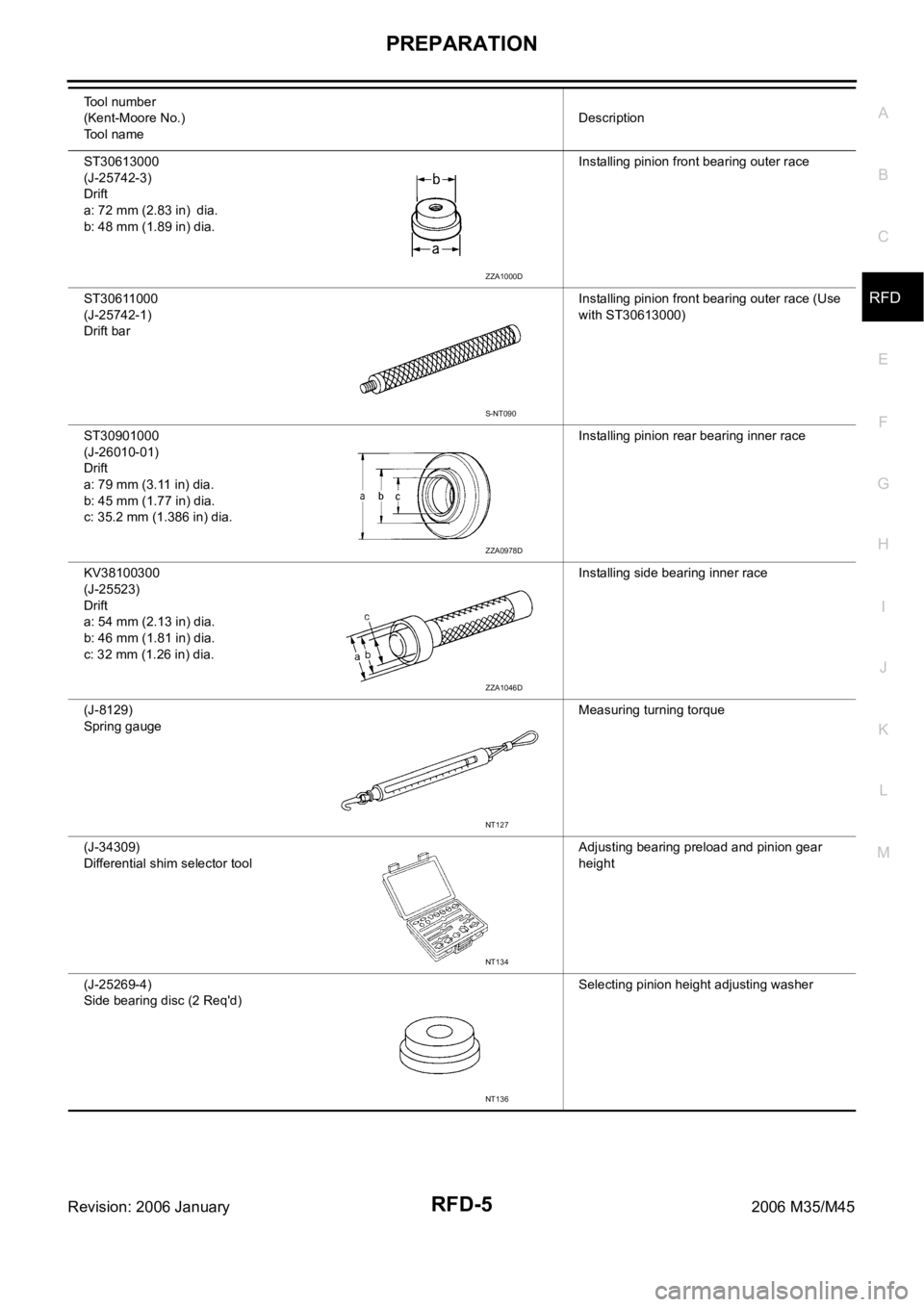
ST30613000
(J-25742-3)
Drift
a: 72 mm (2.83 in) dia.
b: 48 mm (1.89 in) dia.Installing pinion front bearing outer race
ST30611000
(J-25742-1)
Drift barInstalling pinion front bearing outer race (Use
with ST30613000)
ST30901000
(J-26010-01)
Drift
a: 79 mm (3.11 in) dia.
b: 45 mm (1.77 in) dia.
c: 35.2 mm (1.386 in) dia.Installing pinion rear bearing inner race
KV38100300
(J-25523)
Drift
a: 54 mm (2.13 in) dia.
b: 46 mm (1.81 in) dia.
c: 32 mm (1.26 in) dia.Installing side bearing inner race
(J-8129)
Spring gaugeMeasuring turning torque
(J-34309)
Differential shim selector toolAdjusting bearing preload and pinion gear
height
(J-25269-4)
Side bearing disc (2 Req'd) Selecting pinion height adjusting washer Tool number
(Kent-Moore No.)
Tool nameDescription
ZZA1000D
S-NT090
ZZA0978D
ZZA1046D
NT127
NT134
NT136
Page 5061 of 5621
RFD-18
REAR FINAL DRIVE ASSEMBLY
Revision: 2006 January2006 M35/M45
Disassembly and AssemblyNDS000F8
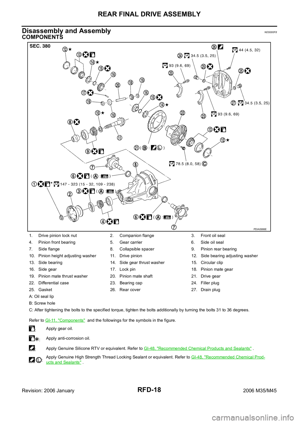
COMPONENTS
1. Drive pinion lock nut 2. Companion flange 3. Front oil seal
4. Pinion front bearing 5. Gear carrier 6. Side oil seal
7. Side flange 8. Collapsible spacer 9. Pinion rear bearing
10. Pinion height adjusting washer 11. Drive pinion 12. Side bearing adjusting washer
13. Side bearing 14. Side gear thrust washer 15. Circular clip
16. Side gear 17. Lock pin 18. Pinion mate gear
19. Pinion mate thrust washer 20. Pinion mate shaft 21. Drive gear
22. Differential case 23. Bearing cap 24. Filler plug
25. Gasket 26. Rear cover 27. Drain plug
A: Oil seal lip
B: Screw hole
C: After tightening the bolts to the specified torque, tighten the bolts additionally by turning the bolts 31 to 36 degrees.
Refer to GI-11, "
Components" and the followings for the symbols in the figure.
:Apply gear oil.
:Apply anti-corrosion oil.
:Apply Genuine Silicone RTV or equivalent. Refer to GI-48, "
Recommended Chemical Products and Sealants" .
:Apply Genuine High Strength Thread Locking Sealant or equivalent. Refer to GI-48, "
Recommended Chemical Prod-
ucts and Sealants" .
PDIA0986E
Page 5064 of 5621
REAR FINAL DRIVE ASSEMBLY
RFD-21
C
E
F
G
H
I
J
K
L
MA
B
RFD
Revision: 2006 January2006 M35/M45
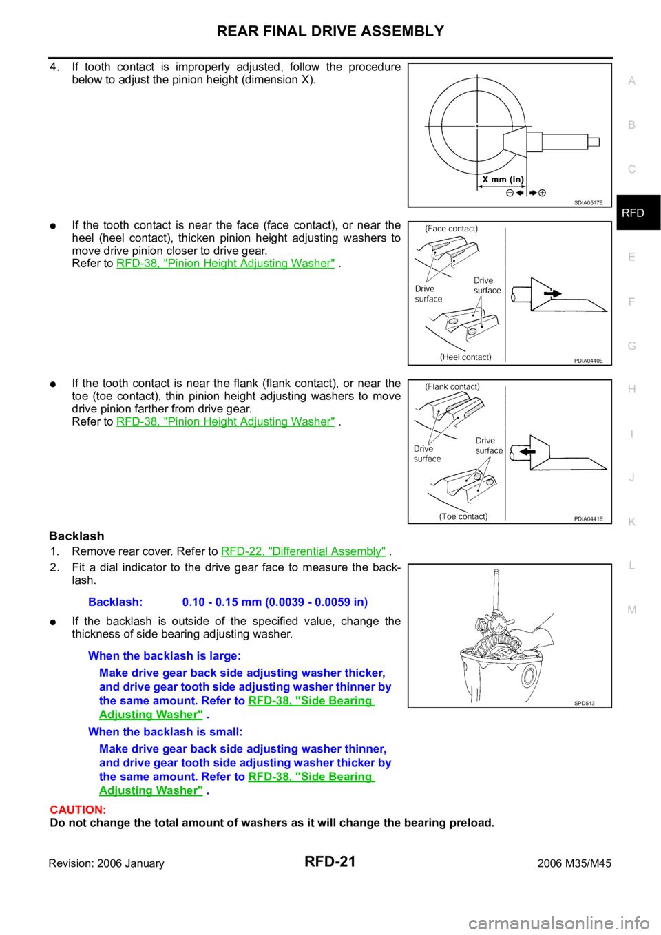
4. If tooth contact is improperly adjusted, follow the procedure
below to adjust the pinion height (dimension X).
If the tooth contact is near the face (face contact), or near the
heel (heel contact), thicken pinion height adjusting washers to
move drive pinion closer to drive gear.
Refer to RFD-38, "
Pinion Height Adjusting Washer" .
If the tooth contact is near the flank (flank contact), or near the
toe (toe contact), thin pinion height adjusting washers to move
drive pinion farther from drive gear.
Refer to RFD-38, "
Pinion Height Adjusting Washer" .
Backlash
1. Remove rear cover. Refer to RFD-22, "Differential Assembly" .
2. Fit a dial indicator to the drive gear face to measure the back-
lash.
If the backlash is outside of the specified value, change the
thickness of side bearing adjusting washer.
CAUTION:
Do not change the total amount of washers as it will change the bearing preload.
SDIA0517E
PDIA0440E
PDIA0441E
Backlash: 0.10 - 0.15 mm (0.0039 - 0.0059 in)
When the backlash is large:
Make drive gear back side adjusting washer thicker,
and drive gear tooth side adjusting washer thinner by
the same amount. Refer to RFD-38, "
Side Bearing
Adjusting Washer" .
When the backlash is small:
Make drive gear back side adjusting washer thinner,
and drive gear tooth side adjusting washer thicker by
the same amount. Refer to RFD-38, "
Side Bearing
Adjusting Washer" .
SPD513
Page 5068 of 5621
REAR FINAL DRIVE ASSEMBLY
RFD-25
C
E
F
G
H
I
J
K
L
MA
B
RFD
Revision: 2006 January2006 M35/M45
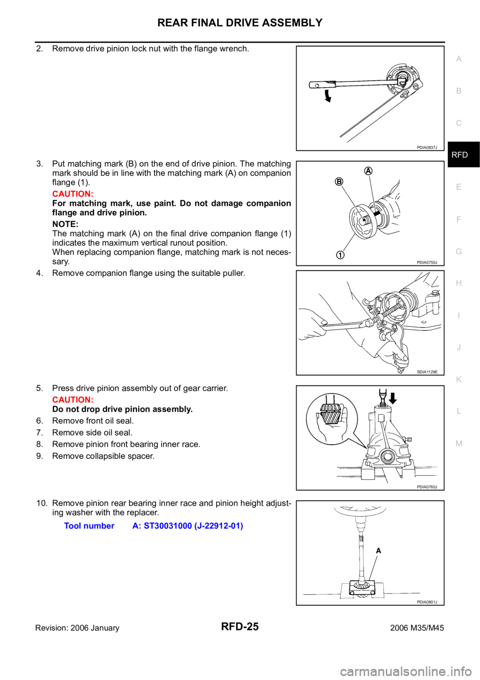
2. Remove drive pinion lock nut with the flange wrench.
3. Put matching mark (B) on the end of drive pinion. The matching
mark should be in line with the matching mark (A) on companion
flange (1).
CAUTION:
For matching mark, use paint. Do not damage companion
flange and drive pinion.
NOTE:
The matching mark (A) on the final drive companion flange (1)
indicates the maximum vertical runout position.
When replacing companion flange, matching mark is not neces-
sary.
4. Remove companion flange using the suitable puller.
5. Press drive pinion assembly out of gear carrier.
CAUTION:
Do not drop drive pinion assembly.
6. Remove front oil seal.
7. Remove side oil seal.
8. Remove pinion front bearing inner race.
9. Remove collapsible spacer.
10. Remove pinion rear bearing inner race and pinion height adjust-
ing washer with the replacer.
PDIA0837J
PDIA0750J
SDIA1129E
PDIA0760J
Tool number A: ST30031000 (J-22912-01)
PDIA0801J