2006 INFINITI M35 coolant temperature
[x] Cancel search: coolant temperaturePage 1416 of 5621
![INFINITI M35 2006 Factory Service Manual ENGINE COOLANT
CO-41
[VK45DE]
C
D
E
F
G
H
I
J
K
L
MA
CO
Revision: 2006 January2006 M35/M45
5. Check drained engine coolant for contaminants such as rust, corrosion or discoloration.
If contaminated, f INFINITI M35 2006 Factory Service Manual ENGINE COOLANT
CO-41
[VK45DE]
C
D
E
F
G
H
I
J
K
L
MA
CO
Revision: 2006 January2006 M35/M45
5. Check drained engine coolant for contaminants such as rust, corrosion or discoloration.
If contaminated, f](/manual-img/42/57023/w960_57023-1415.png)
ENGINE COOLANT
CO-41
[VK45DE]
C
D
E
F
G
H
I
J
K
L
MA
CO
Revision: 2006 January2006 M35/M45
5. Check drained engine coolant for contaminants such as rust, corrosion or discoloration.
If contaminated, flush the engine cooling system. Refer to CO-42, "
FLUSHING COOLING SYSTEM" .
REFILLING ENGINE COOLANT
1. Install reservoir tank if removed, and radiator drain plug.
CAUTION:
Be sure to clean radiator drain plug and install with new O-ring.
If water drain plugs on cylinder block are removed, close and tighten them. Refer to EM-254,
"ASSEMBLY" .
2. Make sure that each hose clamp has been firmly tightened.
3. Remove air relief plug (1) on heater hose.
4. Fill thermostat housing and reservoir tank to specified level.
Refill engine coolant up to filler neck of thermostat housing.
Pour engine coolant through engine coolant filler neck slowly of less than 2 (2-1/8 US qt, 1-3/4
Imp qt) a minute to allow air in system to escape.
Use Genuine Nissan Long Life Antifreeze/Coolant or equivalent mixed with water (distilled or
demineralized). Refer to MA-12, "
RECOMMENDED FLUIDS AND LUBRICANTS" .
When engine coolant overflows air relief hole on heater hose,
install air relief plug.
5. Install radiator cap.
6. Warm up until opening thermostat. Standard for warming-up time is approximately 10 minutes at 3,000
rpm.
Make sure thermostat opening condition by touching radiator hose (lower) to see a flow of warm water.
CAUTION:
Watch water temperature gauge so as not to overheat engine.
7. Stop engine and cool down to less than approximately 50
C (122F).
Cool down using a fan to reduce the time.Radiator drain plug:
: 1.2 Nꞏm (0.12 kg-m, 11 in-lb)
: Engine front
PBIC3394E
Engine coolant capacity
(With reservoir tank at “MAX” level):
Approx. 10.4 (11 US qt, 9-1/8 Imp qt)
Reservoir tank engine coolant capacity
(At “MAX” level):
0.6 (5/8 US qt, 1/2 lmp qt)
Air relief plug:
: 1.2 Nꞏm (0.12 kg-m, 11 in-lb)
SMA412B
Page 1417 of 5621
![INFINITI M35 2006 Factory Service Manual CO-42
[VK45DE]
ENGINE COOLANT
Revision: 2006 January2006 M35/M45
If necessary, refill engine coolant up to filler neck of thermostat housing.
8. Refill reservoir tank to “MAX” level line with engi INFINITI M35 2006 Factory Service Manual CO-42
[VK45DE]
ENGINE COOLANT
Revision: 2006 January2006 M35/M45
If necessary, refill engine coolant up to filler neck of thermostat housing.
8. Refill reservoir tank to “MAX” level line with engi](/manual-img/42/57023/w960_57023-1416.png)
CO-42
[VK45DE]
ENGINE COOLANT
Revision: 2006 January2006 M35/M45
If necessary, refill engine coolant up to filler neck of thermostat housing.
8. Refill reservoir tank to “MAX” level line with engine coolant.
9. Repeat steps 4 through 7 two or more times with radiator cap installed until engine coolant level no longer
drops.
10. Check cooling system for leaks with engine running.
11. Warm up engine, and check for sound of engine coolant flow while running engine from idle up to 3,000
rpm with heater temperature controller set at several position between “COOL” and “WARM”.
Sound may be noticeable at heater unit.
12. Repeat step 11 three times.
13. If sound is heard, bleed air from cooling system by repeating steps 4 through 7 until engine coolant level
no longer drops.
FLUSHING COOLING SYSTEM
1. Install reservoir tank, and radiator drain plug.
CAUTION:
Be sure to clean drain plug and install with new O-ring.
If water drain plugs on cylinder block are removed, close and tighten them. Refer to EM-254,
"ASSEMBLY" .
2. Remove air relief plug (1) on heater hose.
3. Fill thermostat housing with water until water spills from the air relief hole, then close air relief plug. Fill
thermostat housing and reservoir tank with water and reinstall radiator cap.
4. Run engine and warm it up to normal operating temperature.
5. Rev engine two or three times under no-load.
6. Stop engine and wait until it cools down.
7. Drain water from the system. Refer to CO-40, "
DRAINING ENGINE COOLANT" .
8. Repeat steps 1 through 7 until clear water begins to drain from radiator. Radiator drain plug:
: 1.2 Nꞏm (0.12 kg-m, 11 in-lb)
: Engine front
PBIC3394E
Air relief plug:
: 1.2 Nꞏm (0.12 kg-m, 11 in-lb)
Page 1431 of 5621
![INFINITI M35 2006 Factory Service Manual CO-56
[VK45DE]
THERMOSTAT AND WATER CONTROL VALVE
Revision: 2006 January2006 M35/M45
5. Disconnect water suction hose from water inlet.
6. Remove water inlet and thermostat.
CAUTION:
Do not disassembl INFINITI M35 2006 Factory Service Manual CO-56
[VK45DE]
THERMOSTAT AND WATER CONTROL VALVE
Revision: 2006 January2006 M35/M45
5. Disconnect water suction hose from water inlet.
6. Remove water inlet and thermostat.
CAUTION:
Do not disassembl](/manual-img/42/57023/w960_57023-1430.png)
CO-56
[VK45DE]
THERMOSTAT AND WATER CONTROL VALVE
Revision: 2006 January2006 M35/M45
5. Disconnect water suction hose from water inlet.
6. Remove water inlet and thermostat.
CAUTION:
Do not disassemble thermostat.
7. Remove intake manifolds (upper and lower). Refer to EM-179, "
INTAKE MANIFOLD" .
8. Disconnect radiator hose (upper) from thermostat housing.
9. Disconnect heater hoses from water outlet and heater pipe.
10. Remove thermostat housing, water outlet pipe, water connector, water control valve, water outlet and
heater pipe.
CAUTION:
Do not disassemble water control valve.
INSPECTION AFTER REMOVAL
Make sure that valves both in thermostat and water control valve are completely closing at normal tempar-
ature.
Place a thread so that it is caught in the valves of the thermostat
and water control valve. Immerse fully in a container filled with
water. Heat while stirring. (The example in the figure shows ther-
mostat.)
The valve opening temperature is the temperature at which the
valve opens and falls from the thread.
Continue heating. Check the maximum valve lift.
NOTE:
The maximum valve lift standard temperature for water control
valve is the reference value.
After checking the maximum valve lift, lower the water tempera-
ture and check the valve closing temperature.
Standard values:
If the malfunctioning condition, when closing valve at normal temperature, or measured values are out of
the standard, replace thermostat and/or water control valve.
INSTALLATION
Note the following, and install in the reverse order of removal.
CAUTION:
Be careful not to spill engine coolant over engine room. Use rag to absorb engine coolant.
Thermostat and Water Control Valve
Install thermostat and water control valve with the whole circum-
ference of each flange part fit securely inside rubber ring. (The
example in the figure shows thermostat.)
SLC252B
Thermostat Water control valve
Valve opening temperature 80 - 84
C (176 - 183F) 93.5 - 96.5C (200 - 206F)
Maximum valve liftMore than 10 mm/ 95
C
(0.39 in/ 203
F)More than 8 mm/ 108
C
(0.315 in/ 226
F)
Valve closing temperature 77
C (171F) 90C (194F)
PBIC0157E
Page 1433 of 5621
![INFINITI M35 2006 Factory Service Manual CO-58
[VK45DE]
SERVICE DATA AND SPECIFICATIONS (SDS)
Revision: 2006 January2006 M35/M45
SERVICE DATA AND SPECIFICATIONS (SDS)PFP:00030
Standard and LimitNBS004RT
ENGINE COOLANT CAPACITY (APPROXIMATE)
INFINITI M35 2006 Factory Service Manual CO-58
[VK45DE]
SERVICE DATA AND SPECIFICATIONS (SDS)
Revision: 2006 January2006 M35/M45
SERVICE DATA AND SPECIFICATIONS (SDS)PFP:00030
Standard and LimitNBS004RT
ENGINE COOLANT CAPACITY (APPROXIMATE)](/manual-img/42/57023/w960_57023-1432.png)
CO-58
[VK45DE]
SERVICE DATA AND SPECIFICATIONS (SDS)
Revision: 2006 January2006 M35/M45
SERVICE DATA AND SPECIFICATIONS (SDS)PFP:00030
Standard and LimitNBS004RT
ENGINE COOLANT CAPACITY (APPROXIMATE)
Unit: (US qt, Imp qt)
RADIATOR
Unit: kPa (kg/cm2 , psi)
THERMOSTAT
WATER CONTROL VALVE
Engine coolant capacity (With reservoir tank at “MAX” level) 10.4 (11, 9-1/8)
Reservoir tank engine coolant capacity (at “MAX” level) 0.6 (5/8, 1/2)
Radiator cap relief pressureStandard 78 - 98 (0.8 - 1.0, 11 - 14)
Limit 59 (0.6, 9)
Leakage testing pressure 157 (1.6, 23)
ThermostatStandard
Valve opening temperature 80 - 84
C (176 - 183F)
Maximum valve lift More than 10 mm/ 95
C (0.39 in/ 203F)
Valve closing temperature 77
C (171F)
Water control valveStandard
Valve opening temperature 93.5 - 96.5
C (200 - 206F)
Maximum valve lift More than 8 mm/ 108
C (0.315 in/ 226F)
Valve closing temperature 90
C (194F)
Page 1434 of 5621

DI-1
DRIVER INFORMATION SYSTEM
K ELECTRICAL
CONTENTS
C
D
E
F
G
H
I
J
L
M
SECTION DI
A
B
DI
Revision: 2006 January2006 M35/M45
DRIVER INFORMATION SYSTEM
PRECAUTION ............................................................ 3
Precautions for Supplemental Restraint System
(SRS) “AIR BAG” and “SEAT BELT PRE-TEN-
SIONER” .................................................................. 3
PREPARATION ........................................................... 4
Commercial Service Tools ........................................ 4
COMBINATION METERS ........................................... 5
System Description .................................................. 5
UNIFIED METER CONTROL UNIT ...................... 5
UNIFIED METER AND A/C AMP. ......................... 5
POWER SUPPLY AND GROUND CIRCUIT ........ 5
SPEEDOMETER ................................................... 6
TACHOMETER ..................................................... 6
WATER TEMPERATURE GAUGE ........................ 6
FUEL GAUGE ....................................................... 7
ODO/TRIP METER ............................................... 7
METER ILLUMINATION CONTROL ..................... 8
FAIL-SAFE ............................................................ 9
Arrangement of Combination Meter ....................... 10
Component Parts and Harness Connector Location .... 11
Internal Circuit ........................................................ 12
Wiring Diagram — METER — ................................ 13
Terminals and Reference Value for Combination
Meter ...................................................................... 15
Terminals and Reference Value for Unified Meter
and A/C Amp. ......................................................... 16
Self-Diagnosis Mode of Combination Meter ........... 17
SELF-DIAGNOSIS FUNCTION .......................... 17
OPERATION PROCEDURE ............................... 17
CONSULT-II Function (METER A/C AMP) ............. 18
Trouble Diagnosis .................................................. 18
HOW TO PERFORM TROUBLE DIAGNOSIS ... 18
PRELIMINARY CHECK ...................................... 18
Symptom Chart ...................................................... 18
Power Supply and Ground Circuit Inspection ........ 19
Vehicle Speed Signal Inspection ............................ 20
Engine Speed Signal Inspection ............................ 21
Engine Coolant Temperature Signal Inspection ..... 22
Fuel Level Sensor Signal Inspection ...................... 22
Fuel Gauge Pointer Fluctuates, Indicator Wrong Value or Varies ....................................................... 25
Fuel Gauge Does Not Move to FULL Position ....... 25
Electrical Components Inspection .......................... 26
CHECK FUEL LEVEL SENSOR UNIT ................ 26
Removal and Installation of Combination Meter ..... 27
REMOVAL ........................................................
... 27
INSTALLATION ................................................... 27
Disassembly and Assembly of Combination Meter ... 27
DISASSEMBLY ................................................... 27
ASSEMBLY ......................................................... 27
UNIFIED METER AND A/C AMP ...........................
... 28
System Description ................................................. 28
COMBINATION METER CONTROL FUNCTION ... 28
A/C AUTO AMP. FUNCTION ............................... 29
OTHER FUNCTIONS .......................................... 29
Schematic ............................................................... 30
CONSULT-II Function (METER A/C AMP) ............. 31
CONSULT-II BASIC OPERATION ....................... 31
SELF-DIAG RESULTS ........................................ 32
DATA MONITOR ................................................. 33
Power Supply and Ground Circuit Inspection ......... 35
DTC [U1000] CAN Communication Circuit ............. 36
DTC [B2202] Meter Communication Circuit ........... 36
DTC [B2205] Vehicle Speed Circuit ........................ 39
Removal and Installation of Unified Meter and A/C
Amp. ....................................................................... 39
REMOVAL ........................................................
... 39
INSTALLATION ................................................... 39
WARNING LAMPS .................................................... 40
System Description ................................................. 40
OIL PRESSURE WARNING LAMP ..................... 40
Component Parts and Harness Connector Location ... 41
Schematic ............................................................... 42
Wiring Diagram — WARN — .................................. 43
Oil Pressure Warning Lamp Stays Off (Ignition
Switch ON) ............................................................. 53
Oil Pressure Warning Lamp Does Not Turn Off (Oil
Pressure Is Normal) ................................................ 54
Electrical Component Inspection ............................ 55
OIL PRESSURE SWITCH ................................... 55
Page 1439 of 5621

DI-6
COMBINATION METERS
Revision: 2006 January2006 M35/M45
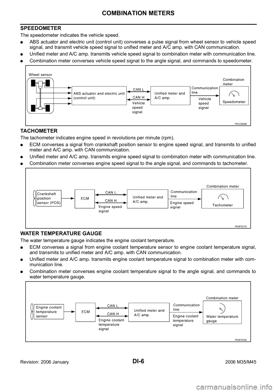
SPEEDOMETER
The speedometer indicates the vehicle speed.
ABS actuator and electric unit (control unit) converses a pulse signal from wheel sensor to vehicle speed
signal, and transmit vehicle speed signal to unified meter and A/C amp. with CAN communication.
Unified meter and A/C amp. transmits vehicle speed signal to combination meter with communication line.
Combination meter converses vehicle speed signal to the angle signal, and commands to speedometer.
TACHOMETER
The tachometer indicates engine speed in revolutions per minute (rpm).
ECM converses a signal from crankshaft position sensor to engine speed signal, and transmits to unified
meter and A/C amp. with CAN communication.
Unified meter and A/C amp. transmits engine speed signal to combination meter with communication line.
Combination meter converses engine speed signal to the angle signal, and commands to tachometer.
WATER TEMPERATURE GAUGE
The water temperature gauge indicates the engine coolant temperature.
ECM converses a signal from engine coolant temperature sensor to engine coolant temperature signal,
and transmits to unified meter and A/C amp. with CAN communication.
Unified meter and A/C amp. transmits engine coolant temperature signal to combination meter with com-
munication line.
Combination meter converses engine coolant temperature signal to the angle signal, and commands to
water temperature gauge.
PKIC0696E
PKIB7631E
PKIB7632E
Page 1451 of 5621

DI-18
COMBINATION METERS
Revision: 2006 January2006 M35/M45
CONSULT-II Function (METER A/C AMP)NKS003U3
Refer to DI-31, "CONSULT-II Function (METER A/C AMP)" in “UNIFIED METER AND A/C AMP”.
Trouble DiagnosisNKS003U4
HOW TO PERFORM TROUBLE DIAGNOSIS
1. Confirm the symptom or customer complaint.
2. Perform preliminary check. Refer to DI-18, "
PRELIMINARY CHECK" .
3. According to the symptom chart, make sure the cause of the symptom and repair or replace applicable
parts. Refer to DI-18, "
Symptom Chart" .
4. Does the meter operate normally? If yes, GO TO 5. If no, GO TO 2.
5. INSPECTION END
PRELIMINARY CHECK
1. CHECK OPERATION SELF-DIAGNOSIS MODE OF COMBINATION METER
Perform self-diagnosis mode of combination meter. Refer to DI-17, "
OPERATION PROCEDURE" .
Does self
-diagnosis mode operate?
YES >> GO TO 2.
NO >> GO TO 3.
2. CHECK UNIFIED METER AND A/C AMP. (CONSULT-II)
Perform self-diagnosis of unified meter and A/C amp. Refer to DI-31, "
CONSULT-II Function (METER A/C
AMP)" .
Self
-diagnostic results content
No malfunction detected>>INSPECTION END
Malfunction detected>>Check applicable parts, and repair or replace corresponding parts.
3. CHECK POWER SUPPLY AND GROUND CIRCUIT OF COMBINATION METER
Check power supply and ground circuit of combination meter. Refer to DI-19, "
Power Supply and Ground Cir-
cuit Inspection" .
OK or NG
OK >> Replace combination meter.
NG >> Repair power supply and ground circuit of combination meter.
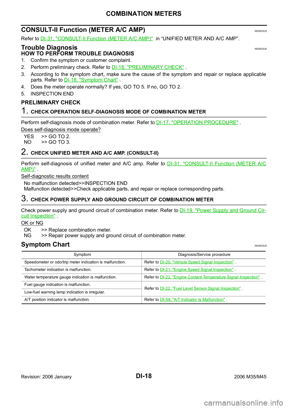
Symptom ChartNKS003U5
Symptom Diagnosis/Service procedure
Speedometer or odo/trip meter indication is malfunction. Refer to DI-20, "
Vehicle Speed Signal Inspection" .
Tachometer indication is malfunction. Refer to DI-21, "
Engine Speed Signal Inspection" .
Water temperature gauge indication is malfunction. Refer to DI-22, "
Engine Coolant Temperature Signal Inspection" .
Fuel gauge indication is malfunction.
Refer to DI-22, "
Fuel Level Sensor Signal Inspection" .
Low-fuel warning lamp indication is irregular.
A/T position indicator is malfunction. Refer to DI-59, "
A/T Indicator Is Malfunction" .
Page 1455 of 5621

DI-22
COMBINATION METERS
Revision: 2006 January2006 M35/M45
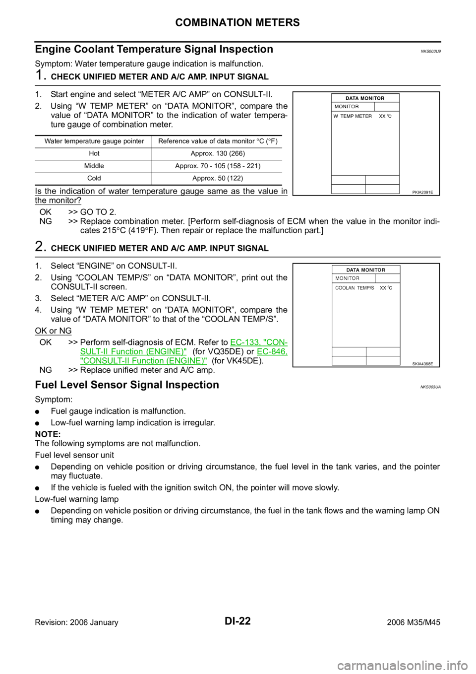
Engine Coolant Temperature Signal InspectionNKS003U9
Symptom: Water temperature gauge indication is malfunction.
1. CHECK UNIFIED METER AND A/C AMP. INPUT SIGNAL
1. Start engine and select “METER A/C AMP” on CONSULT-II.
2. Using “W TEMP METER” on “DATA MONITOR”, compare the
value of “DATA MONITOR” to the indication of water tempera-
ture gauge of combination meter.
Is the indication of water temperature gauge same as the value in
the monitor?
OK >> GO TO 2.
NG >> Replace combination meter. [Perform self-diagnosis of ECM when the value in the monitor indi-
cates 215
C (419F). Then repair or replace the malfunction part.]
2. CHECK UNIFIED METER AND A/C AMP. INPUT SIGNAL
1. Select “ENGINE” on CONSULT-II.
2. Using “COOLAN TEMP/S” on “DATA MONITOR”, print out the
CONSULT-II screen.
3. Select “METER A/C AMP” on CONSULT-II.
4. Using “W TEMP METER” on “DATA MONITOR”, compare the
value of “DATA MONITOR” to that of the “COOLAN TEMP/S”.
OK or NG
OK >> Perform self-diagnosis of ECM. Refer to EC-133, "CON-
SULT-II Function (ENGINE)" (for VQ35DE) or EC-846,
"CONSULT-II Function (ENGINE)" (for VK45DE).
NG >> Replace unified meter and A/C amp.
Fuel Level Sensor Signal InspectionNKS003UA
Symptom:
Fuel gauge indication is malfunction.
Low-fuel warning lamp indication is irregular.
NOTE:
The following symptoms are not malfunction.
Fuel level sensor unit
Depending on vehicle position or driving circumstance, the fuel level in the tank varies, and the pointer
may fluctuate.
If the vehicle is fueled with the ignition switch ON, the pointer will move slowly.
Low-fuel warning lamp
Depending on vehicle position or driving circumstance, the fuel in the tank flows and the warning lamp ON
timing may change.
Water temperature gauge pointer Reference value of data monitor C (F)
Hot Approx. 130 (266)
Middle Approx. 70 - 105 (158 - 221)
Cold Approx. 50 (122)
PKIA2091E
SKIA4368E