2006 INFINITI M35 torque
[x] Cancel search: torquePage 3334 of 5621
![INFINITI M35 2006 Factory Service Manual CYLINDER BLOCK
EM-271
[VK45DE]
C
D
E
F
G
H
I
J
K
L
MA
EM
Revision: 2006 January2006 M35/M45
Piston Skirt Diameter
Measure the outer diameter of piston skirt with micrometer.
Measure point “H” (Dis INFINITI M35 2006 Factory Service Manual CYLINDER BLOCK
EM-271
[VK45DE]
C
D
E
F
G
H
I
J
K
L
MA
EM
Revision: 2006 January2006 M35/M45
Piston Skirt Diameter
Measure the outer diameter of piston skirt with micrometer.
Measure point “H” (Dis](/manual-img/42/57023/w960_57023-3333.png)
CYLINDER BLOCK
EM-271
[VK45DE]
C
D
E
F
G
H
I
J
K
L
MA
EM
Revision: 2006 January2006 M35/M45
Piston Skirt Diameter
Measure the outer diameter of piston skirt with micrometer.
Measure point “H” (Distance from the top): 42 mm (1.65 in)
Piston to Cylinder Bore Clearance
Calculate by piston skirt diameter and cylinder bore inner diameter (direction “Y”, position “B”).
(Clearance) = (Cylinder bore inner diameter) – (Piston skirt diameter).
If the calculated value exceeds the limit, replace piston and piston pin assembly. Refer to EM-260, "HOW
TO SELECT PISTON" .
Re-boring Cylinder Bore
1. Cylinder bore size is determined by adding piston to cylinder bore clearance to piston skirt diameter.
2. Install main bearing caps and main bearing, and tighten to the specified torque. Otherwise, cylinder bores
may be distorted in final assembly.
3. Cut cylinder bores.
NOTE:
When any cylinder needs boring, all other cylinders must also be bored.
Do not cut too much out of cylinder bore at a time. Cut only 0.05 mm (0.0020 in) or so in diameter at a
time.
4. Hone cylinders to obtain the specified piston to cylinder bore clearance.
5. Measure finished cylinder bore for the out-of-round and taper.
NOTE:
Measurement should be done after cylinder bore cools down.
CRANKSHAFT MAIN JOURNAL DIAMETER
Measure the outer diameter of crankshaft main journals with micrometer. Standard
: 92.980 - 93.010 mm (3.6606 - 3.6618 in)
PBIC0125E
PBIC0126E
Standard : 0.010 - 0.030 mm (0.0004 - 0.0012 in)
Limit : 0.08 mm (0.0031 in)
Re-bored size calculation: D = A + B – C
where,
D: Bored diameter
A: Piston skirt diameter as measured
B: Piston to cylinder bore clearance (standard value)
C: Honing allowance 0.02 mm (0.0008 in)
Page 3336 of 5621
![INFINITI M35 2006 Factory Service Manual CYLINDER BLOCK
EM-273
[VK45DE]
C
D
E
F
G
H
I
J
K
L
MA
EM
Revision: 2006 January2006 M35/M45
CONNECTING ROD BEARING OIL CLEARANCE
Method by Calculation
Install connecting rod bearings to connectin INFINITI M35 2006 Factory Service Manual CYLINDER BLOCK
EM-273
[VK45DE]
C
D
E
F
G
H
I
J
K
L
MA
EM
Revision: 2006 January2006 M35/M45
CONNECTING ROD BEARING OIL CLEARANCE
Method by Calculation
Install connecting rod bearings to connectin](/manual-img/42/57023/w960_57023-3335.png)
CYLINDER BLOCK
EM-273
[VK45DE]
C
D
E
F
G
H
I
J
K
L
MA
EM
Revision: 2006 January2006 M35/M45
CONNECTING ROD BEARING OIL CLEARANCE
Method by Calculation
Install connecting rod bearings to connecting rod and cap, and
tighten connecting rod bolts to the specified torque. Refer to
EM-254, "
ASSEMBLY" for the tightening procedure.
Measure the inner diameter of connecting rod bearing with
inside micrometer.
(Bearing oil clearance) = (Connecting rod bearing inner diameter) –
(Crankshaft pin journal diameter)
If the calculated value exceeds the limit, select proper connecting rod bearing according to connecting rod
big end diameter and crankshaft pin journal diameter to obtain the specified bearing oil clearance. Refer
to EM-261, "
HOW TO SELECT CONNECTING ROD BEARING" .
Method of Using Plastigage
Remove oil and dust on crankshaft pin journal and the surfaces of each bearing completely.
Cut plastigage slightly shorter than the bearing width, and place it in crankshaft axial direction, avoiding oil
holes.
Install connecting rod bearings to connecting rod and cap, and tighten connecting rod bolts to the speci-
fied torque. Refer to EM-254, "
ASSEMBLY" for the tightening procedure.
CAUTION:
Do not rotate crankshaft.
Remove connecting rod bearing cap and bearing, and using
scale on plastigage bag, measure the plastigage width.
NOTE:
The procedure when the measured value exceeds the limit is
same as that described in the “Method by Calculation”.Standard : 0.020 - 0.045 mm (0.0008 - 0.0018 in)
(actual clearance)
Limit : 0.055 mm (0.0022 in)
PBIC1642E
PBIC1149E
Page 3337 of 5621
![INFINITI M35 2006 Factory Service Manual EM-274
[VK45DE]
CYLINDER BLOCK
Revision: 2006 January2006 M35/M45
MAIN BEARING OIL CLEARANCE
Method by Calculation
Install main bearings to cylinder block and main bearing caps,
and tighten INFINITI M35 2006 Factory Service Manual EM-274
[VK45DE]
CYLINDER BLOCK
Revision: 2006 January2006 M35/M45
MAIN BEARING OIL CLEARANCE
Method by Calculation
Install main bearings to cylinder block and main bearing caps,
and tighten](/manual-img/42/57023/w960_57023-3336.png)
EM-274
[VK45DE]
CYLINDER BLOCK
Revision: 2006 January2006 M35/M45
MAIN BEARING OIL CLEARANCE
Method by Calculation
Install main bearings to cylinder block and main bearing caps,
and tighten main bearing cap bolts with main bearing to the
specified torque. Refer to EM-254, "
ASSEMBLY" for the tighten-
ing procedure.
Measure the inner diameter of main bearing with bore gauge.
(Bearing clearance) = (Main bearing inner diameter) – (Crankshaft main journal diameter)
If the calculated value exceeds the limit, select proper main bearing according to main bearing inner diam-
eter and crankshaft main journal diameter to obtain the specified bearing oil clearance. Refer to EM-262,
"HOW TO SELECT MAIN BEARING" .
Method of Using Plastigage
Remove oil and dust on crankshaft main journal and the surfaces of each bearing completely.
Cut plastigage slightly shorter than the bearing width, and place it in crankshaft axial direction, avoiding oil
holes.
Install main bearings to cylinder block and main bearing caps, and tighten main bearing bolts with main
bearing to the specified torque. Refer to EM-254, "
ASSEMBLY" for the tightening procedure.
CAUTION:
Do not rotate crankshaft.
Remove main bearing caps and bearings, and using scale on
plastigage bag, measure the plastigage width.
NOTE:
The procedure when the measured value exceeds the limit is
same as that described in the “Method by Calculation”.
PBIC1644E
Standard
No . 1 and 5 journal : 0.001 - 0.011 mm (0.00004 - 0.0004 in)
No. 2, 3 and 4 journal : 0.007 - 0.017 mm (0.0003 - 0.0007 in)
Limit
No. 1 and 5 journal : 0.021 mm (0.0008 in)
No. 2, 3 and 4 journal : 0.027 mm (0.0011 in)
PBIC1149E
Page 3338 of 5621
![INFINITI M35 2006 Factory Service Manual CYLINDER BLOCK
EM-275
[VK45DE]
C
D
E
F
G
H
I
J
K
L
MA
EM
Revision: 2006 January2006 M35/M45
CRUSH HEIGHT OF MAIN BEARING
When main bearing cap is removed after being tightened to the
specified torq INFINITI M35 2006 Factory Service Manual CYLINDER BLOCK
EM-275
[VK45DE]
C
D
E
F
G
H
I
J
K
L
MA
EM
Revision: 2006 January2006 M35/M45
CRUSH HEIGHT OF MAIN BEARING
When main bearing cap is removed after being tightened to the
specified torq](/manual-img/42/57023/w960_57023-3337.png)
CYLINDER BLOCK
EM-275
[VK45DE]
C
D
E
F
G
H
I
J
K
L
MA
EM
Revision: 2006 January2006 M35/M45
CRUSH HEIGHT OF MAIN BEARING
When main bearing cap is removed after being tightened to the
specified torque with main bearings installed, the tip end of bear-
ing must protrude. Refer to EM-254, "
ASSEMBLY" for the tight-
ening procedure.
If the standard is not met, replace main bearings.
CRUSH HEIGHT OF CONNECTING ROD BEARING
When connecting rod bearing cap is removed after being tight-
ened to the specified torque with connecting rod bearings
installed, the tip end of bearing must protrude. Refer to EM-254,
"ASSEMBLY" for the tightening procedure.
If the standard is not met, replace connecting rod bearings.
DRIVE PLATE
Check drive plate and signal plate for deformation or cracks.
CAUTION:
Do not disassemble drive plate.
Do not place drive plate with signal plate facing down.
When handling signal plate, take care not to damage or
scratch it.
Handle signal plate in a manner that prevents it from
becoming magnetized.
If anything is found, replace drive plate.Standard : There must be crush height.
SEM502G
Standard : There must be crush height.
PBIC1646E
PBIC2367E
Page 3356 of 5621

EXHAUST SYSTEM
EX-5
C
D
E
F
G
H
I
J
K
L
MA
EX
Revision: 2006 January2006 M35/M45
Removal and InstallationNBS005RL
CAUTION:
Be sure to use genuine exhaust system parts or equivalents which are specially designed for heat
resistance, corrosion resistance, and shape.
Perform the operation with the exhaust system fully cooled down because the system will be hot
just after engine stops.
Be careful not to cut your hand on the heat insulator edge.
REMOVAL
Disconnect each joint and mounting using power tool.
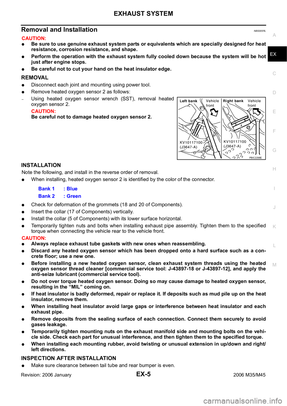
Remove heated oxygen sensor 2 as follows:
–Using heated oxygen sensor wrench (SST), removal heated
oxygen sensor 2.
CAUTION:
Be careful not to damage heated oxygen sensor 2.
INSTALLATION
Note the following, and install in the reverse order of removal.
When installing, heated oxygen sensor 2 is identified by the color of the connector.
Check for deformation of the grommets (18 and 20 of Components).
Insert the collar (17 of Components) vertically.
Install the collar (5 of Components) with its lower surface horizontal.
Temporarily tighten nuts and bolts when installing exhaust pipe assembly. Tighten them to the specified
torque when connecting the vehicle rear to the vehicle front.
CAUTION:
Always replace exhaust tube gaskets with new ones when reassembling.
Discard any heated oxygen sensor which has been dropped onto a hard surface such as a con-
crete floor; use a new one.
Before installing a new heated oxygen sensor, clean exhaust system threads using the heated
oxygen sensor thread cleaner [commercial service tool: J-43897-18 or J-43897-12], and apply the
anti-seize lubricant (commercial service tool).
Do not over torque heated oxygen sensor. Doing so may cause damage to heated oxygen sensor,
resulting in the “MIL” coming on.
If heat insulator is badly deformed, repair or replace it. If deposits such as mud pile up on the heat
insulator, remove them.
When installing heat insulator avoid large gaps or interference between heat insulator and each
exhaust pipe.
Remove deposits from the sealing surface of each connection. Connect them securely to avoid
gases leakage.
Temporarily tighten mounting nuts on the exhaust manifold side and mounting bolts on the vehi-
cle side. Check each part for unusual interference, and then tighten them to the specified torque.
When installing each mounting rubber, avoid twisting or unusual extension in up/down and right/
left directions.
INSPECTION AFTER INSTALLATION
Make sure clearance between tail tube and rear bumper is even.
PBIC2298E
Bank 1 : Blue
Bank 2 : Green
Page 3358 of 5621

EXHAUST SYSTEM
EX-7
C
D
E
F
G
H
I
J
K
L
MA
EX
Revision: 2006 January2006 M35/M45
Removal and installationNBS005RN
CAUTION:
Be sure to use genuine exhaust system parts or equivalents which are specially designed for heat
resistance, corrosion resistance, and shape.
Perform the operation with the exhaust system fully cooled down because the system will be hot
just after engine stops.
Be careful not to cut your hand on the heat insulator edge.
REMOVAL
Disconnect each joint and mounting using power tool.
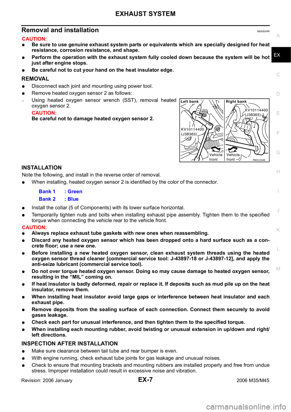
Remove heated oxygen sensor 2 as follows:
–Using heated oxygen sensor wrench (SST), removal heated
oxygen sensor 2.
CAUTION:
Be careful not to damage heated oxygen sensor 2.
INSTALLATION
Note the following, and install in the reverse order of removal.
When installing, heated oxygen sensor 2 is identified by the color of the connector.
Install the collar (5 of Components) with its lower surface horizontal.
Temporarily tighten nuts and bolts when installing exhaust pipe assembly. Tighten them to the specified
torque when connecting the vehicle rear to the vehicle front.
CAUTION:
Always replace exhaust tube gaskets with new ones when reassembling.
Discard any heated oxygen sensor which has been dropped onto a hard surface such as a con-
crete floor; use a new one.
Before installing a new heated oxygen sensor, clean exhaust system threads using the heated
oxygen sensor thread cleaner [commercial service tool: J-43897-18 or J-43897-12], and apply the
anti-seize lubricant (commercial service tool).
Do not over torque heated oxygen sensor. Doing so may cause damage to heated oxygen sensor,
resulting in the “MIL” coming on.
If heat insulator is badly deformed, repair or replace it. If deposits such as mud pile up on the heat
insulator, remove them.
When installing heat insulator avoid large gaps or interference between heat insulator and each
exhaust pipe.
Remove deposits from the sealing surface of each connection. Connect them securely to avoid
gases leakage.
Check each part for unusual interference, and then tighten them to the specified torque.
When installing each mounting rubber, avoid twisting or unusual extension in up/down and right/
left directions.
INSPECTION AFTER INSTALLATION
Make sure clearance between tail tube and rear bumper is even.
With engine running, check exhaust tube joints for gas leakage and unusual noises.
Check to ensure that mounting brackets and mounting rubbers are installed properly and free from undue
stress. Improper installation could result in excessive noise and vibration.
PBIC2334E
Bank 1 : Green
Bank 2 : Blue
Page 3362 of 5621
![INFINITI M35 2006 Factory Service Manual PREPARATION
FAX-3
C
E
F
G
H
I
J
K
L
MA
B
FA X
Revision: 2006 January2006 M35/M45
PREPARATIONPFP:00002
Special Service Tools [SST]NDS000FC
The actual shapes of Kent-Moore tools may differ from those of INFINITI M35 2006 Factory Service Manual PREPARATION
FAX-3
C
E
F
G
H
I
J
K
L
MA
B
FA X
Revision: 2006 January2006 M35/M45
PREPARATIONPFP:00002
Special Service Tools [SST]NDS000FC
The actual shapes of Kent-Moore tools may differ from those of](/manual-img/42/57023/w960_57023-3361.png)
PREPARATION
FAX-3
C
E
F
G
H
I
J
K
L
MA
B
FA X
Revision: 2006 January2006 M35/M45
PREPARATIONPFP:00002
Special Service Tools [SST]NDS000FC
The actual shapes of Kent-Moore tools may differ from those of special service tools illustrated here.
Commercial Service ToolsNDS000FD
Tool number
(Kent-Moore No.)
Tool nameDescription
KV40107300
(–)
Boot band crimping toolInstalling boot band
KV40107500
(–)
Drive shaft attachmentRemoving drive shaft
KV38107900
(–)
Protector
a: 32 mm (1.26 in) dia.Installing drive shaft
KV38100500
(–)
Drift
a: 80 mm (3.15 in) dia.
b: 60 mm (2.36 in) dia.Installing drive shaft plug
KV38102200
(–)
Drift
a: 90 mm (3.54 in) dia.
b: 31 mm (1.22 in) dia.Installing drive shaft plug
ZZA1229D
ZZA1230D
ZZA0835D
ZZA0701D
ZZA0920D
Tool name Description
Power tool
Removing wheel nuts
Removing torque member fixing bolts
Removing hub lock nut
PBIC0190E
Page 3364 of 5621

FRONT WHEEL HUB AND KNUCKLE
FAX-5
C
E
F
G
H
I
J
K
L
MA
B
FA X
Revision: 2006 January2006 M35/M45
FRONT WHEEL HUB AND KNUCKLEPFP:40202
On-Vehicle Inspection and ServiceNDS000FF
Make sure that the mounting conditions (looseness, backlash) of each component and component conditions
(wear, damage) are normal.
WHEEL BEARING INSPECTION
Move wheel hub and bearing assembly in the axial direction by hand. Make sure there is no looseness of
wheel bearing.
Rotate wheel hub and make sure that is no unusual noise or other irregular conditions. If there is any of
irregular conditions, replace wheel hub and bearing assembly
Removal and InstallationNDS000FG
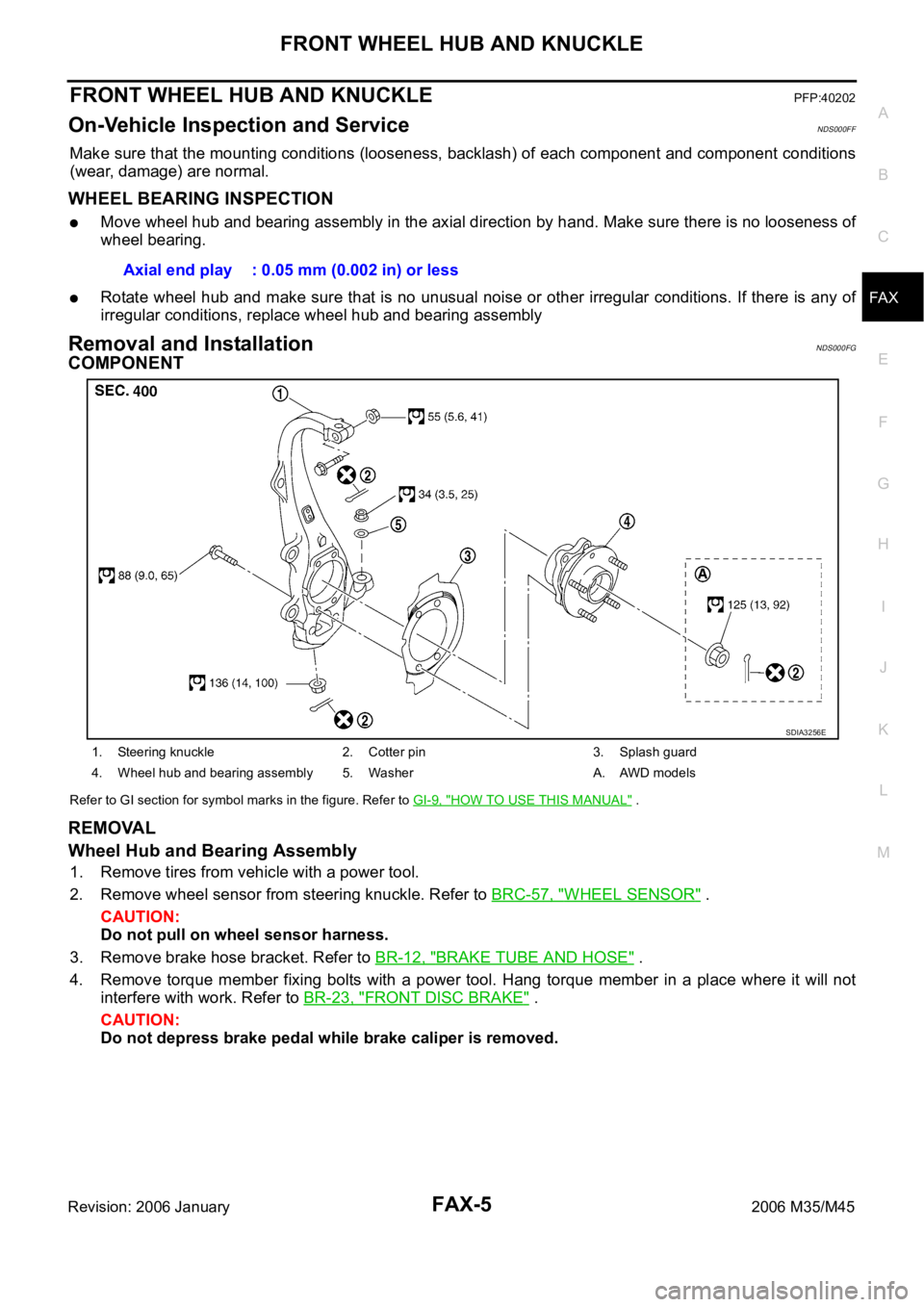
COMPONENT
Refer to GI section for symbol marks in the figure. Refer to GI-9, "HOW TO USE THIS MANUAL" .
REMOVAL
Wheel Hub and Bearing Assembly
1. Remove tires from vehicle with a power tool.
2. Remove wheel sensor from steering knuckle. Refer to BRC-57, "
WHEEL SENSOR" .
CAUTION:
Do not pull on wheel sensor harness.
3. Remove brake hose bracket. Refer to BR-12, "
BRAKE TUBE AND HOSE" .
4. Remove torque member fixing bolts with a power tool. Hang torque member in a place where it will not
interfere with work. Refer to BR-23, "
FRONT DISC BRAKE" .
CAUTION:
Do not depress brake pedal while brake caliper is removed.Axial end play : 0.05 mm (0.002 in) or less
1. Steering knuckle 2. Cotter pin 3. Splash guard
4. Wheel hub and bearing assembly 5. Washer A. AWD models
SDIA3256E