2006 INFINITI M35 check oil
[x] Cancel search: check oilPage 3167 of 5621
EM-104
[VQ35DE]
CYLINDER HEAD
Revision: 2006 January2006 M35/M45
Cylinder Head Distortion
NOTE:
When performing this inspection, cylinder block distortion should be also checking. Refer to EM-143, "
CYLIN-
DER BLOCK DISTORTION" .
1. Using a scraper, wipe off oil, scale, gasket, sealant and carbon deposits from surface of cylinder head.
CAUTION:
Do not allow gasket fragments to enter engine oil or engine coolant passages.
2. At each of several locations on bottom surface of cylinder head,
measure the distortion in six directions.
If it exceeds the limit, replace cylinder head.
INSTALLATION
1. Install new cylinder head gaskets.
2. Turn crankshaft until No. 1 piston is set at TDC.
Crankshaft key should line up with the right bank cylinder cen-
ter line as shown in the figure.
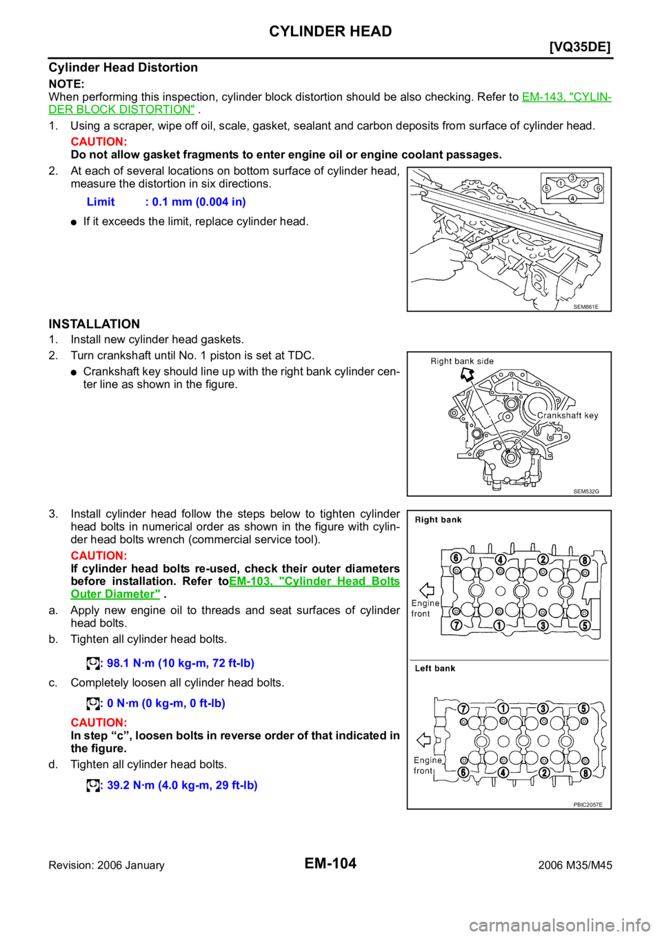
3. Install cylinder head follow the steps below to tighten cylinder
head bolts in numerical order as shown in the figure with cylin-
der head bolts wrench (commercial service tool).
CAUTION:
If cylinder head bolts re-used, check their outer diameters
before installation. Refer toEM-103, "
Cylinder Head Bolts
Outer Diameter" .
a. Apply new engine oil to threads and seat surfaces of cylinder
head bolts.
b. Tighten all cylinder head bolts.
c. Completely loosen all cylinder head bolts.
CAUTION:
In step “c”, loosen bolts in reverse order of that indicated in
the figure.
d. Tighten all cylinder head bolts.Limit : 0.1 mm (0.004 in)
SEM861E
SEM532G
: 98.1 Nꞏm (10 kg-m, 72 ft-lb)
: 0 Nꞏm (0 kg-m, 0 ft-lb)
: 39.2 Nꞏm (4.0 kg-m, 29 ft-lb)
PBIC2057E
Page 3168 of 5621
![INFINITI M35 2006 Factory Service Manual CYLINDER HEAD
EM-105
[VQ35DE]
C
D
E
F
G
H
I
J
K
L
MA
EM
Revision: 2006 January2006 M35/M45
e. Turn all cylinder head bolts 90 degrees clockwise (angle tighten-
ing).
CAUTION:
Check the tightening a](/manual-img/42/57023/w960_57023-3167.png "INFINITI M35 2006 Factory Service Manual CYLINDER HEAD
EM-105
[VQ35DE]
C
D
E
F
G
H
I
J
K
L
MA
EM
Revision: 2006 January2006 M35/M45
e. Turn all cylinder head bolts 90 degrees clockwise (angle tighten-
ing).
CAUTION:
Check the tightening a")
CYLINDER HEAD
EM-105
[VQ35DE]
C
D
E
F
G
H
I
J
K
L
MA
EM
Revision: 2006 January2006 M35/M45
e. Turn all cylinder head bolts 90 degrees clockwise (angle tighten-
ing).
CAUTION:
Check the tightening angle by using the angle wrench
(SST). Avoid judgment by visual inspection without SST.
Check tightening angle indicated on the angle wrench indica-
tor plate.
f. Turn all cylinder head bolts 90 degrees clockwise again (angle
tightening).
4. After installing cylinder head, measure distance between front
end faces of cylinder block and cylinder head (left and right
banks).
If measured value is out of the standard, re-install cylinder
head.
5. Install in the reverse order of removal after this step.
INSPECTION AFTER INSTALLATION
Inspection for Leaks
The following are procedures for checking fluids leak, lubricates leak and exhaust gases leak.
Before starting engine, check oil/fluid levels including engine coolant and engine oil. If less than required
quantity, fill to the specified level. Refer to MA-12, "
RECOMMENDED FLUIDS AND LUBRICANTS" .
Use procedure below to check for fuel leakage.
–Turn ignition switch “ON” (with engine stopped). With fuel pressure applied to fuel piping, check for fuel
leakage at connection points.
–Start engine. With engine speed increased, check again for fuel leakage at connection points.
Run engine to check for unusual noise and vibration.
Warm up engine thoroughly to make sure there is no leakage of fuel, exhaust gases, or any oil/fluids
including engine oil and engine coolant.
Bleed air from lines and hoses of applicable lines, such as in cooling system.
After cooling down engine, again check oil/fluid levels including engine oil and engine coolant. Refill to the
specified level, if necessary.
Summary of the inspection items:
* Transmission/transaxle/CVT fluid, power steering fluid, brake fluid, etc.
PBIC0888E
Standard : 14.1 - 14.9 mm (0.555 - 0.587 in)
EMQ0662D
Item Before starting engine Engine running After engine stopped
Engine coolant Level Leakage Level
Engine oil Level Leakage Level
Other oils and fluid* Level Leakage Level
Fuel Leakage Leakage Leakage
Exhaust gases — Leakage —
Page 3173 of 5621
![INFINITI M35 2006 Factory Service Manual EM-110
[VQ35DE]
CYLINDER HEAD
Revision: 2006 January2006 M35/M45
4. Heat cylinder head to 110 to 130C (230 to 266F) by soaking in
heated oil.
5. Using the valve guide drift (commercial service tool),](/manual-img/42/57023/w960_57023-3172.png "INFINITI M35 2006 Factory Service Manual EM-110
[VQ35DE]
CYLINDER HEAD
Revision: 2006 January2006 M35/M45
4. Heat cylinder head to 110 to 130C (230 to 266F) by soaking in
heated oil.
5. Using the valve guide drift (commercial service tool),")
EM-110
[VQ35DE]
CYLINDER HEAD
Revision: 2006 January2006 M35/M45
4. Heat cylinder head to 110 to 130C (230 to 266F) by soaking in
heated oil.
5. Using the valve guide drift (commercial service tool), press valve
guide from camshaft side to the dimensions as in the figure.
WA R N I N G :
Cylinder head contains heat. When working, wear protec-
tive equipment to avoid getting burned.
6. Using the valve guide reamer (commercial service tool), apply
reamer finish to valve guide.
VALVE SEAT CONTACT
After confirming that the dimensions of valve guides and valves
are within the specifications, perform this procedure.
Apply prussian blue (or white lead) onto contacting surface of
valve seat to check the condition of the valve contact on the sur-
face.
Check if the contact area band is continuous all around the cir-
cumference.
If not, grind to adjust valve fitting and check again. If the contact-
ing surface still has “NG” conditions even after the re-check,
replace valve seat. Refer to EM-110, "
VALVE SEAT REPLACE-
MENT" .
VALVE SEAT REPLACEMENT
When valve seat is removed, replace with oversized [0.5 mm (0.020 in)] valve seat.
1. Bore out old seat until it collapses. Boring should not continue beyond the bottom face of the seat recess
in cylinder head. Set the machine depth stop to ensure this. Refer to EM-156, "
Va l v e S e a t" .
CAUTION:
Prevent to scratch cylinder head by excessive boring.
SEM008A
Projection “L”
Intake and exhaust
: 12.6 - 12.8 mm (0.496 - 0.504 in)
SEM950E
Standard:
Intake and exhaust
: 6.000 - 6.018 mm (0.2362 - 0.2369 in)
SEM932C
SBIA0322E
Page 3174 of 5621
![INFINITI M35 2006 Factory Service Manual CYLINDER HEAD
EM-111
[VQ35DE]
C
D
E
F
G
H
I
J
K
L
MA
EM
Revision: 2006 January2006 M35/M45
2. Ream cylinder head recess diameter for service valve seat.
Be sure to ream in circles concentric to valve](/manual-img/42/57023/w960_57023-3173.png "INFINITI M35 2006 Factory Service Manual CYLINDER HEAD
EM-111
[VQ35DE]
C
D
E
F
G
H
I
J
K
L
MA
EM
Revision: 2006 January2006 M35/M45
2. Ream cylinder head recess diameter for service valve seat.
Be sure to ream in circles concentric to valve")
CYLINDER HEAD
EM-111
[VQ35DE]
C
D
E
F
G
H
I
J
K
L
MA
EM
Revision: 2006 January2006 M35/M45
2. Ream cylinder head recess diameter for service valve seat.
Be sure to ream in circles concentric to valve guide center.
This will enable valve to fit correctly.
3. Heat cylinder head to 110 to 130
C (230 to 266F) by soaking in
heated oil.
4. Provide valve seats cooled well with dry ice. Force fit valve seat into cylinder head.
WAR NING :
Cylinder head contains heat. When working, wear protective equipment to avoid getting burned.
CAUTION:
Avoid directly touching cold valve seats.
5. Using the valve seat cutter set (commercial service tool) or valve
seat grinder, finish seat to the specified dimensions. Refer to
EM-156, "
Va l v e S e a t" .
CAUTION:
When using the valve seat cutter, firmly grip cutter handle
with both hands. Then, press on the contacting surface all
around the circumference to cut in a single drive. Improper
pressure on with cutter or cutting many different times may
result in stage valve seat.
6. Using compound, grind to adjust valve fitting.
7. Check again for normal contact. Refer to EM-110, "
VA LV E S E AT C O N TA C T" .
VALVE SPRING SQUARENESS
Set a try square along the side of valve spring and rotate spring.
Measure the maximum clearance between the top of spring and
try square.
If it exceeds the limit, replace valve spring.Oversize [0.5 mm (0.020 in)]
Intake : 38.500 - 38.516 mm (1.5157 - 1.5164 in)
Exhaust : 32.700 - 32.716 mm (1.2874 - 1.2880 in)
SEM795A
SEM008A
SEM934C
Limit : 2.1 mm (0.083 in)
PBIC0080E
Page 3180 of 5621
![INFINITI M35 2006 Factory Service Manual ENGINE ASSEMBLY
EM-117
[VQ35DE]
C
D
E
F
G
H
I
J
K
L
MA
EM
Revision: 2006 January2006 M35/M45
INSPECTION AFTER INSTALLATION
Inspection for Leaks
The following are procedures for checking fluids leak, l](/manual-img/42/57023/w960_57023-3179.png "INFINITI M35 2006 Factory Service Manual ENGINE ASSEMBLY
EM-117
[VQ35DE]
C
D
E
F
G
H
I
J
K
L
MA
EM
Revision: 2006 January2006 M35/M45
INSPECTION AFTER INSTALLATION
Inspection for Leaks
The following are procedures for checking fluids leak, l")
ENGINE ASSEMBLY
EM-117
[VQ35DE]
C
D
E
F
G
H
I
J
K
L
MA
EM
Revision: 2006 January2006 M35/M45
INSPECTION AFTER INSTALLATION
Inspection for Leaks
The following are procedures for checking fluids leak, lubricates leak and exhaust gases leak.
Before starting engine, check oil/fluid levels including engine coolant and engine oil. If less than required
quantity, fill to the specified level. Refer to MA-12, "
RECOMMENDED FLUIDS AND LUBRICANTS" .
Use procedure below to check for fuel leakage.
–Turn ignition switch “ON” (with engine stopped). With fuel pressure applied to fuel piping, check for fuel
leakage at connection points.
–Start engine. With engine speed increased, check again for fuel leakage at connection points.
Run engine to check for unusual noise and vibration.
Warm up engine thoroughly to make sure there is no leakage of fuel, exhaust gases, or any oil/fluids
including engine oil and engine coolant.
Bleed air from lines and hoses of applicable lines, such as in cooling system.
After cooling down engine, again check oil/fluid levels including engine oil and engine coolant. Refill to the
specified level, if necessary.
Summary of the inspection items:
* Transmission/transaxle/CVT fluid, power steering fluid, brake fluid, etc. Item Before starting engine Engine running After engine stopped
Engine coolant Level Leakage Level
Engine oil Level Leakage Level
Other oils and fluid* Level Leakage Level
Fuel Leakage Leakage Leakage
Exhaust gases — Leakage —
Page 3184 of 5621
![INFINITI M35 2006 Factory Service Manual ENGINE ASSEMBLY
EM-121
[VQ35DE]
C
D
E
F
G
H
I
J
K
L
MA
EM
Revision: 2006 January2006 M35/M45
Separation Work
1. Install engine slingers into front of cylinder head (right bank) and
rear of cylinder he](/manual-img/42/57023/w960_57023-3183.png "INFINITI M35 2006 Factory Service Manual ENGINE ASSEMBLY
EM-121
[VQ35DE]
C
D
E
F
G
H
I
J
K
L
MA
EM
Revision: 2006 January2006 M35/M45
Separation Work
1. Install engine slingers into front of cylinder head (right bank) and
rear of cylinder he")
ENGINE ASSEMBLY
EM-121
[VQ35DE]
C
D
E
F
G
H
I
J
K
L
MA
EM
Revision: 2006 January2006 M35/M45
Separation Work
1. Install engine slingers into front of cylinder head (right bank) and
rear of cylinder head (left bank).
To protect rocker cover against damage caused by tilting of
engine slinger, insert spacer between cylinder head and
engine rear lower slinger, in direction shown in the figure.
NOTE:
Spacer is a component part of engine rear upper slinger
assembly.
2. Remove power steering oil pump from engine side. Refer to PS-29, "
POWER STEERING OIL PUMP" .
3. Remove engine mounting insulators (RH and LH) under side nuts with power tool.
4. Lift with hoist and separate the engine, the transmission assembly, the transfer assembly and the front
final drive assembly from front suspension member.
CAUTION:
Before and during this lifting, always check if any harnesses are left connected.
Avoid damage to and oil/grease smearing or spills onto engine mounting insulator.
5. Remove alternator. Refer to SC-23, "
CHARGING SYSTEM" .
6. Remove starter motor. Refer to SC-10, "
STARTING SYSTEM" .
7. Remove front propeller shaft from the front final drive assembly side. Refer to PR-4, "
FRONT PROPEL-
LER SHAFT" .
8. Separate the engine from the transmission assembly. Refer to AT-271, "
TRANSMISSION ASSEMBLY" .
9. Remove the front final drive assembly from oil pan (upper). Refer to FFD-13, "
FRONT FINAL DRIVE
ASSEMBLY" .
10. Remove each engine mounting insulator and each engine mounting bracket from the engine with power
tool.
INSTALLATION
Note the following, and install in the reverse order of removal.
Do not allow engine mounting insulator to be damage and careful no engine oil gets on it.
For a location with a positioning pin, insert it securely into hole of mating part.
For a part with a specified installation orientation, refer to component figure in EM-35, "Components (AWD
Models)" . Slinger bolts:
: 28.0 Nꞏm (2.9 kg-m, 21 ft-lb)
PBIC2061E
KBIA1017E
Page 3185 of 5621
![INFINITI M35 2006 Factory Service Manual EM-122
[VQ35DE]
ENGINE ASSEMBLY
Revision: 2006 January2006 M35/M45
When installing engine mounting bracket (RH and LH) on cylin-
der block, tighten two upper bolts (shown as “A” in the](/manual-img/42/57023/w960_57023-3184.png "INFINITI M35 2006 Factory Service Manual EM-122
[VQ35DE]
ENGINE ASSEMBLY
Revision: 2006 January2006 M35/M45
When installing engine mounting bracket (RH and LH) on cylin-
der block, tighten two upper bolts (shown as “A” in the")
EM-122
[VQ35DE]
ENGINE ASSEMBLY
Revision: 2006 January2006 M35/M45
When installing engine mounting bracket (RH and LH) on cylin-
der block, tighten two upper bolts (shown as “A” in the figure)
first. Then tighten two lower bolts (shown as “B” in the figure).
Install engine mounting bracket (RH) (lower) as follows:
–Temporarily tighten mounting bolts (shown as “C”, “D” and “E” in
the figure).
–Tighten mounting bolts to the specified torque with following
mounting surfaces touched.
• Engine mounting bracket (RH) to engine mounting bracket (RH)
(lower) (shown as “C” and “D” in figure).
• Front final drive to engine mounting bracket (RH) (lower) (shown
as “E” in figure).
Make sure all engine mounting insulators are seated properly,
then tighten mounting nuts.
INSPECTION AFTER INSTALLATION
Inspection for Leaks
The following are procedures for checking fluids leak, lubricates leak and exhaust gases leak.
Before starting engine, check oil/fluid levels including engine coolant and engine oil. If less than required
quantity, fill to the specified level. Refer to MA-12, "
RECOMMENDED FLUIDS AND LUBRICANTS" .
Use procedure below to check for fuel leakage.
–Turn ignition switch “ON” (with engine stopped). With fuel pressure applied to fuel piping, check for fuel
leakage at connection points.
–Start engine. With engine speed increased, check again for fuel leakage at connection points.
Run engine to check for unusual noise and vibration.
Warm up engine thoroughly to make sure there is no leakage of fuel, exhaust gases, or any oil/fluids
including engine oil and engine coolant.
Bleed air from lines and hoses of applicable lines, such as in cooling system.
After cooling down engine, again check oil/fluid levels including engine oil and engine coolant. Refill to the
specified level, if necessary.
Summary of the inspection items:
* Transmission/transaxle/CVT fluid, power steering fluid, brake fluid, etc.
PBIC3826E
Item Before starting engine Engine running After engine stopped
Engine coolant Level Leakage Level
Engine oil Level Leakage Level
Other oils and fluid* Level Leakage Level
Fuel Leakage Leakage Leakage
Exhaust gases — Leakage —
Page 3189 of 5621
![INFINITI M35 2006 Factory Service Manual EM-126
[VQ35DE]
CYLINDER BLOCK
Revision: 2006 January2006 M35/M45
5. Drain engine coolant by removing water drain plugs from cylin-
der block both sides at “B” and “C” and cylinder bl](/manual-img/42/57023/w960_57023-3188.png "INFINITI M35 2006 Factory Service Manual EM-126
[VQ35DE]
CYLINDER BLOCK
Revision: 2006 January2006 M35/M45
5. Drain engine coolant by removing water drain plugs from cylin-
der block both sides at “B” and “C” and cylinder bl")
EM-126
[VQ35DE]
CYLINDER BLOCK
Revision: 2006 January2006 M35/M45
5. Drain engine coolant by removing water drain plugs from cylin-
der block both sides at “B” and “C” and cylinder block front side
at “A” as shown in the figure.
6. Remove the following parts:
Oil pans (lower and upper); Refer to EM-29, "OIL PAN AND OIL STRAINER" .
Front and rear timing chain case; Refer to EM-64, "TIMING CHAIN" .
Cylinder head; Refer to EM-101, "CYLINDER HEAD" .
7. Remove knock sensor.
CAUTION:
Carefully handle sensor avoiding shocks.
8. Remove pilot converter using the pilot bushing puller (SST) as
necessary.
9. Remove rear oil seal retainer.
Remove by inserting a screwdriver between main bearing cap and rear oil seal retainer.
CAUTION:
If rear oil seal retainer is removed, replace it with new one.
NOTE:
Regard both rear oil seal and retainer as an assembly.
10. Remove baffle plate from main bearing beam (2WD models).
11. Remove piston and connecting rod assembly with the following procedure:
Before removing piston and connecting rod assembly, check the connecting rod side clearance. Refer
to EM-140, "
CONNECTING ROD SIDE CLEARANCE" .
CAUTION:
Be careful not to drop connecting rod bearing, and to scratch the surface.
a. Position crankshaft pin corresponding to connecting rod to be removed onto the bottom dead center.
PBIC2610E
SEM005G