2006 INFINITI M35 check
[x] Cancel search: checkPage 3155 of 5621
![INFINITI M35 2006 Factory Service Manual EM-92
[VQ35DE]
CAMSHAFT
Revision: 2006 January2006 M35/M45
INSPECTION AFTER INSTALLATION
Inspection of Camshaft Sprocket (INT) Oil Groove
CAUTION:
Perform this inspection only when DTC P0011 or](/manual-img/42/57023/w960_57023-3154.png "INFINITI M35 2006 Factory Service Manual EM-92
[VQ35DE]
CAMSHAFT
Revision: 2006 January2006 M35/M45
INSPECTION AFTER INSTALLATION
Inspection of Camshaft Sprocket (INT) Oil Groove
CAUTION:
Perform this inspection only when DTC P0011 or")
EM-92
[VQ35DE]
CAMSHAFT
Revision: 2006 January2006 M35/M45
INSPECTION AFTER INSTALLATION
Inspection of Camshaft Sprocket (INT) Oil Groove
CAUTION:
Perform this inspection only when DTC P0011 or P0021 are detected in self-diagnostic results of
CONSULT-II and it is directed according to inspection procedure of EC section. Refer to EC-137,
"SELF-DIAG RESULTS MODE" .
Check when engine ins cold so as to prevent burns from any splashing engine oil.
1. Check the engine oil level. Refer to LU-7, "
ENGINE OIL" .
2. Perform the following procedure so as to prevent the engine from being unintentionally started while
checking.
a. Release fuel pressure. Refer to EC-98, "
FUEL PRESSURE RELEASE" .
b. Disconnect ignition coil and injector harness connectors.
3. Remove intake valve timing control solenoid valve. Refer to EM-84, "
CAMSHAFT" .
4. Crank the engine, and then make sure that engine oil comes out
from camshaft bracket (No. 1) oil hole. End crank after checking.
WA R N I N G :
Be careful not to touch rotating parts (drive belts, idler pul-
ley, and crankshaft pulley, etc.).
CAUTION:
Engine oil may squirt from intake valve timing control sole-
noid valve installation hole during cranking. Use a shop
cloth to prevent the engine components and the vehicle. Do
not allow engine oil to get on rubber components such as
drive belt or engine mount insulators. Immediately wipe off
any splashed engine oil.
Clean oil groove between oil strainer and intake valve timing control solenoid valve if engine oil does not
come out from camshaft bracket (No. 1) oil hole. Refer to LU-5, "
LUBRICATION SYSTEM" .
5. Remove components between intake valve timing control solenoid valve and camshaft sprocket (INT),
and then check each oil groove for clogging.
Clean oil groove if necessary. Refer to LU-5, "LUBRICATION SYSTEM" .
6. After inspection, install removed parts.
Inspection for Leaks
The following are procedures for checking fluids leak, lubricates leak.
Before starting engine, check oil/fluid levels including engine coolant and engine oil. If less than required
quantity, fill to the specified level. Refer to MA-12, "
RECOMMENDED FLUIDS AND LUBRICANTS" .
Use procedure below to check for fuel leakage.
–Turn ignition switch “ON” (with engine stopped). With fuel pressure applied to fuel piping, check for fuel
leakage at connection points.
–Start engine. With engine speed increased, check again for fuel leakage at connection points.
Run engine to check for unusual noise and vibration.
NOTE:
If hydraulic pressure inside timing chain tensioner drops after removal/installation, slack in the guide may
generate a pounding noise during and just after engine start. However, this is normal. Noise will stop after
hydraulic pressure rises.
Warm up engine thoroughly to make sure there is no leakage of fuel, or any oil/fluids including engine oil
and engine coolant.
Bleed air from lines and hoses of applicable lines, such as in cooling system.
After cooling down engine, again check oil/fluid levels including engine oil and engine coolant. Refill to the
specified level, if necessary.
PBIC2869E
Page 3160 of 5621
![INFINITI M35 2006 Factory Service Manual CAMSHAFT
EM-97
[VQ35DE]
C
D
E
F
G
H
I
J
K
L
MA
EM
Revision: 2006 January2006 M35/M45
Thickness of new valve lifter can be identified by stamp marks
on the reverse side (inside the cylinder).
Stamp ma](/manual-img/42/57023/w960_57023-3159.png "INFINITI M35 2006 Factory Service Manual CAMSHAFT
EM-97
[VQ35DE]
C
D
E
F
G
H
I
J
K
L
MA
EM
Revision: 2006 January2006 M35/M45
Thickness of new valve lifter can be identified by stamp marks
on the reverse side (inside the cylinder).
Stamp ma")
CAMSHAFT
EM-97
[VQ35DE]
C
D
E
F
G
H
I
J
K
L
MA
EM
Revision: 2006 January2006 M35/M45
Thickness of new valve lifter can be identified by stamp marks
on the reverse side (inside the cylinder).
Stamp mark 788U or 788R indicates 7.88 mm (0.3102 in) in
thickness.
NOTE:
Two types of stamp marks are used for parallel setting and for
manufacturer identification.
Available thickness of valve lifter: 27 sizes with range 7.88 to 8.40 mm (0.3102 to 0.3307 in) in steps of
0.02 mm (0.0008 in) (when manufactured at factory). Refer to EM-153, "
Available Valve Lifter" .
6. Install selected valve lifter.
7. Install camshaft. Refer to EM-89, "
INSTALLATION" .
8. Manually turn crankshaft pulley a few turns.
9. Make sure that the valve clearances for cold engine are within the specifications by referring to the speci-
fied values. Refer to EM-93, "
INSPECTION" .
10. Install all removal parts in the reverse order of removal. Refer to EM-89, "
INSTALLATION" .
11. Warm up the engine, and check for unusual noise and vibration. t
1 = Removed valve lifter thickness
C
1= Measured valve clearance
C
2= Standard valve clearance:
Intake : 0.30 mm (0.012 in)
Exhaust : 0.33 mm (0.013 in)
KBIA0119E
Page 3164 of 5621
![INFINITI M35 2006 Factory Service Manual CYLINDER HEAD
EM-101
[VQ35DE]
C
D
E
F
G
H
I
J
K
L
MA
EM
Revision: 2006 January2006 M35/M45
CYLINDER HEADPFP:11041
On-Vehicle ServiceNBS004NR
CHECKING COMPRESSION PRESSURE
1. Warm up engine thoroughly.](/manual-img/42/57023/w960_57023-3163.png "INFINITI M35 2006 Factory Service Manual CYLINDER HEAD
EM-101
[VQ35DE]
C
D
E
F
G
H
I
J
K
L
MA
EM
Revision: 2006 January2006 M35/M45
CYLINDER HEADPFP:11041
On-Vehicle ServiceNBS004NR
CHECKING COMPRESSION PRESSURE
1. Warm up engine thoroughly.")
CYLINDER HEAD
EM-101
[VQ35DE]
C
D
E
F
G
H
I
J
K
L
MA
EM
Revision: 2006 January2006 M35/M45
CYLINDER HEADPFP:11041
On-Vehicle ServiceNBS004NR
CHECKING COMPRESSION PRESSURE
1. Warm up engine thoroughly. Then, stop it.
2. Release fuel pressure. Refer to EC-98, "
FUEL PRESSURE RELEASE" .
3. Disconnect fuel pump fuse to avoid fuel injection during mea-
surement.
4. Remove engine cover with power tool. Refer to EM-19, "
INTAKE MANIFOLD COLLECTOR" .
5. Remove ignition coil and spark plug from each cylinder. Refer to EM-42, "
IGNITION COIL" and EM-43,
"SPARK PLUG (PLATINUM-TIPPED TYPE)" .
6. Connect engine tachometer (not required in use of CONSULT-ll).
7. Install compression gauge with an adapter (commercial service
tool) onto spark plug hole.
Use the adapter whose picking up end inserted to spark plug
hole is smaller than 20 mm (0.79 in) in diameter. Otherwise, it
may be caught by cylinder head during removal.
8. With accelerator pedal fully depressed, turn ignition switch to “START” for cranking. When the gauge
pointer stabilizes, read the compression pressure and the engine rpm. Perform these steps to check each
cylinder.
Compression pressure:
Unit: kPa (kg/cm2 , psi) /rpm
CAUTION:
Always use a fully changed battery to obtain the specified engine speed.
SBIA0466E
PBIC0900E
SBIA0533E
Standard Minimum Deference limit between cylinders
1,275 (13.0, 185) / 300 981 (10.0, 142) / 300 98 (1.0, 14) / 300
Page 3165 of 5621
![INFINITI M35 2006 Factory Service Manual EM-102
[VQ35DE]
CYLINDER HEAD
Revision: 2006 January2006 M35/M45
If the engine speed is out of the specified range, check battery liquid for proper gravity. Check the
engine speed aga](/manual-img/42/57023/w960_57023-3164.png "INFINITI M35 2006 Factory Service Manual EM-102
[VQ35DE]
CYLINDER HEAD
Revision: 2006 January2006 M35/M45
If the engine speed is out of the specified range, check battery liquid for proper gravity. Check the
engine speed aga")
EM-102
[VQ35DE]
CYLINDER HEAD
Revision: 2006 January2006 M35/M45
If the engine speed is out of the specified range, check battery liquid for proper gravity. Check the
engine speed again with normal battery gravity.
If compression pressure is below minimum value, check valve clearances and parts associated with
combustion chamber (valve, valve seat, piston, piston ring, cylinder bore, cylinder head, cylinder head
gasket). After the checking, measure compression pressure again.
If some cylinder has low compression pressure, pour small amount of engine oil into the spark plug hole
of the cylinder to re-check it for compression.
–If the added engine oil improves the compression, piston rings may be worn out or damaged. Check
piston rings and replace if necessary.
–If the compression pressure remains at low level despite the addition of engine oil, valves may be mal-
functioning. Check valves for damage. Replace valve or valve seat accordingly.
If two adjacent cylinders have respectively low compression pressure and their compression remains
low even after the addition of engine oil, cylinder head gaskets are leaking. In such a case, replace cyl-
inder head gaskets.
9. After inspection is completed, install removed parts.
10. Start the engine, and make sure that the engine runs smoothly.
11. Perform trouble diagnosis. If DTC appears, erase it. Refer to EC-100, "
TROUBLE DIAGNOSIS" .
ComponentsNBS004NS
Removal and InstallationNBS004NT
REMOVAL
1. Remove camshaft. Refer to EM-84, "CAMSHAFT" .
NOTE:
It is also possible to perform the following steps 2 and 3 just before removing camshaft.
1. Engine rear lower slinger 2. Cylinder head (left bank) 3. Cylinder head bolt
4. Cylinder head (right bank) 5. Cylinder head gasket (right bank)6. Cylinder head gasket (left bank)
7. Oil level gauge guide
SBIA0581E
Page 3167 of 5621
EM-104
[VQ35DE]
CYLINDER HEAD
Revision: 2006 January2006 M35/M45
Cylinder Head Distortion
NOTE:
When performing this inspection, cylinder block distortion should be also checking. Refer to EM-143, "
CYLIN-
DER BLOCK DISTORTION" .
1. Using a scraper, wipe off oil, scale, gasket, sealant and carbon deposits from surface of cylinder head.
CAUTION:
Do not allow gasket fragments to enter engine oil or engine coolant passages.
2. At each of several locations on bottom surface of cylinder head,
measure the distortion in six directions.
If it exceeds the limit, replace cylinder head.
INSTALLATION
1. Install new cylinder head gaskets.
2. Turn crankshaft until No. 1 piston is set at TDC.
Crankshaft key should line up with the right bank cylinder cen-
ter line as shown in the figure.
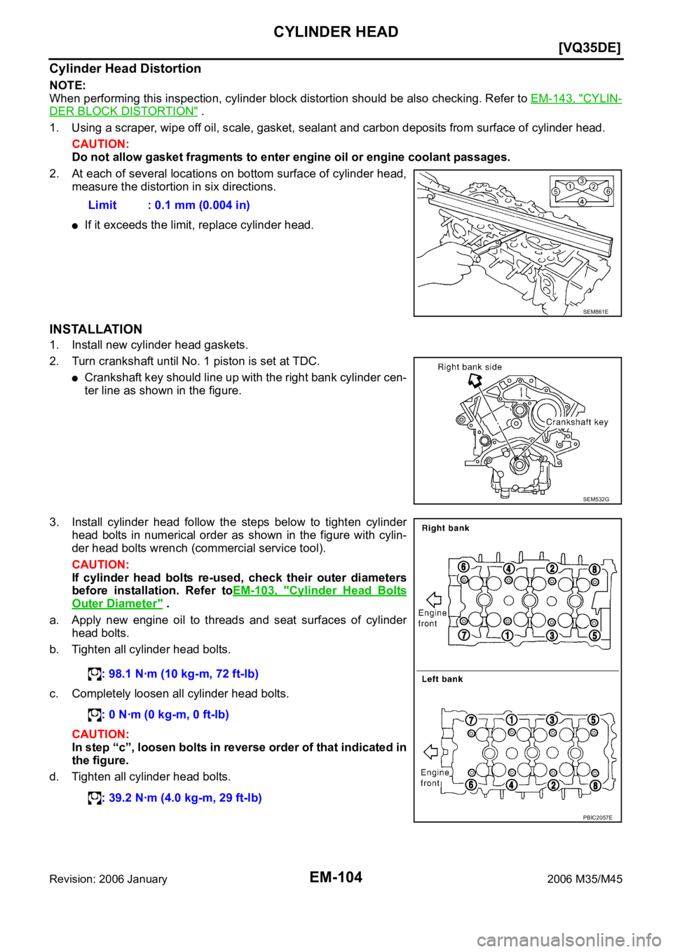
3. Install cylinder head follow the steps below to tighten cylinder
head bolts in numerical order as shown in the figure with cylin-
der head bolts wrench (commercial service tool).
CAUTION:
If cylinder head bolts re-used, check their outer diameters
before installation. Refer toEM-103, "
Cylinder Head Bolts
Outer Diameter" .
a. Apply new engine oil to threads and seat surfaces of cylinder
head bolts.
b. Tighten all cylinder head bolts.
c. Completely loosen all cylinder head bolts.
CAUTION:
In step “c”, loosen bolts in reverse order of that indicated in
the figure.
d. Tighten all cylinder head bolts.Limit : 0.1 mm (0.004 in)
SEM861E
SEM532G
: 98.1 Nꞏm (10 kg-m, 72 ft-lb)
: 0 Nꞏm (0 kg-m, 0 ft-lb)
: 39.2 Nꞏm (4.0 kg-m, 29 ft-lb)
PBIC2057E
Page 3168 of 5621
![INFINITI M35 2006 Factory Service Manual CYLINDER HEAD
EM-105
[VQ35DE]
C
D
E
F
G
H
I
J
K
L
MA
EM
Revision: 2006 January2006 M35/M45
e. Turn all cylinder head bolts 90 degrees clockwise (angle tighten-
ing).
CAUTION:
Check the tightening a](/manual-img/42/57023/w960_57023-3167.png "INFINITI M35 2006 Factory Service Manual CYLINDER HEAD
EM-105
[VQ35DE]
C
D
E
F
G
H
I
J
K
L
MA
EM
Revision: 2006 January2006 M35/M45
e. Turn all cylinder head bolts 90 degrees clockwise (angle tighten-
ing).
CAUTION:
Check the tightening a")
CYLINDER HEAD
EM-105
[VQ35DE]
C
D
E
F
G
H
I
J
K
L
MA
EM
Revision: 2006 January2006 M35/M45
e. Turn all cylinder head bolts 90 degrees clockwise (angle tighten-
ing).
CAUTION:
Check the tightening angle by using the angle wrench
(SST). Avoid judgment by visual inspection without SST.
Check tightening angle indicated on the angle wrench indica-
tor plate.
f. Turn all cylinder head bolts 90 degrees clockwise again (angle
tightening).
4. After installing cylinder head, measure distance between front
end faces of cylinder block and cylinder head (left and right
banks).
If measured value is out of the standard, re-install cylinder
head.
5. Install in the reverse order of removal after this step.
INSPECTION AFTER INSTALLATION
Inspection for Leaks
The following are procedures for checking fluids leak, lubricates leak and exhaust gases leak.
Before starting engine, check oil/fluid levels including engine coolant and engine oil. If less than required
quantity, fill to the specified level. Refer to MA-12, "
RECOMMENDED FLUIDS AND LUBRICANTS" .
Use procedure below to check for fuel leakage.
–Turn ignition switch “ON” (with engine stopped). With fuel pressure applied to fuel piping, check for fuel
leakage at connection points.
–Start engine. With engine speed increased, check again for fuel leakage at connection points.
Run engine to check for unusual noise and vibration.
Warm up engine thoroughly to make sure there is no leakage of fuel, exhaust gases, or any oil/fluids
including engine oil and engine coolant.
Bleed air from lines and hoses of applicable lines, such as in cooling system.
After cooling down engine, again check oil/fluid levels including engine oil and engine coolant. Refill to the
specified level, if necessary.
Summary of the inspection items:
* Transmission/transaxle/CVT fluid, power steering fluid, brake fluid, etc.
PBIC0888E
Standard : 14.1 - 14.9 mm (0.555 - 0.587 in)
EMQ0662D
Item Before starting engine Engine running After engine stopped
Engine coolant Level Leakage Level
Engine oil Level Leakage Level
Other oils and fluid* Level Leakage Level
Fuel Leakage Leakage Leakage
Exhaust gases — Leakage —
Page 3171 of 5621
![INFINITI M35 2006 Factory Service Manual EM-108
[VQ35DE]
CYLINDER HEAD
Revision: 2006 January2006 M35/M45
8. Install valve collet.
Compress valve spring with the valve spring compressor, the
attachment and the adapter (SST). Install va](/manual-img/42/57023/w960_57023-3170.png "INFINITI M35 2006 Factory Service Manual EM-108
[VQ35DE]
CYLINDER HEAD
Revision: 2006 January2006 M35/M45
8. Install valve collet.
Compress valve spring with the valve spring compressor, the
attachment and the adapter (SST). Install va")
EM-108
[VQ35DE]
CYLINDER HEAD
Revision: 2006 January2006 M35/M45
8. Install valve collet.
Compress valve spring with the valve spring compressor, the
attachment and the adapter (SST). Install valve collet with a
magnet hand.
CAUTION:
When working, take care not to damage valve lifter holes.
Tap valve stem edge lightly with plastic hammer after installa-
tion to check its installed condition.
9. Install valve lifter.
Install it in the original position.
10. Install spark plug tube.
Press-fit spark plug tube as follows:
a. Remove old locking sealant adhering to cylinder head mounting hole.
b. Apply sealant to area within approximately 12 mm (0.47 in) from edge of spark plug tube press-fit side.
Use Genuine High Strength Locking Sealant or equivalent. Refer to GI-48, "
RECOMMENDED
CHEMICAL PRODUCTS AND SEALANTS" .
c. Using drift, press-fit spark plug tube so that its height “H” is as
specified in the figure.
CAUTION:
When press-fitting, take care not to deform spark plug
tube.
After press-fitting, wipe off liquid gasket protruding onto
cylinder-head upper face.
11. Install spark plug with spark plug wrench (commercial service tool).
Inspection after DisassemblyNBS004NV
VALVE DIMENSIONS
Check the dimensions of each valve. For the dimensions, refer to EM-154, "Valve Dimensions" .
If dimensions are out of the standard, replace valve and check valve seat contact. Refer to EM-110,
"VA LV E S E AT C O N TA C T" .
VALVE GUIDE CLEARANCE
Valve Stem Diameter
Measure the diameter of valve stem with micrometer.
Valve Guide Inner Diameter
Measure the inner diameter of valve guide with bore gauge.
PBIC1803E
Standard press-fit height “H”:
: 38.1 - 39.1 mm (1.500 - 1.539 in)
PBIC2638E
Standard
Intake : 5.965 - 5.980 mm (0.2348 - 0.2354 in)
Exhaust : 5.955 - 5.970 mm (0.2344 - 0.2350 in)
SEM938C
Page 3173 of 5621
![INFINITI M35 2006 Factory Service Manual EM-110
[VQ35DE]
CYLINDER HEAD
Revision: 2006 January2006 M35/M45
4. Heat cylinder head to 110 to 130C (230 to 266F) by soaking in
heated oil.
5. Using the valve guide drift (commercial service tool),](/manual-img/42/57023/w960_57023-3172.png "INFINITI M35 2006 Factory Service Manual EM-110
[VQ35DE]
CYLINDER HEAD
Revision: 2006 January2006 M35/M45
4. Heat cylinder head to 110 to 130C (230 to 266F) by soaking in
heated oil.
5. Using the valve guide drift (commercial service tool),")
EM-110
[VQ35DE]
CYLINDER HEAD
Revision: 2006 January2006 M35/M45
4. Heat cylinder head to 110 to 130C (230 to 266F) by soaking in
heated oil.
5. Using the valve guide drift (commercial service tool), press valve
guide from camshaft side to the dimensions as in the figure.
WA R N I N G :
Cylinder head contains heat. When working, wear protec-
tive equipment to avoid getting burned.
6. Using the valve guide reamer (commercial service tool), apply
reamer finish to valve guide.
VALVE SEAT CONTACT
After confirming that the dimensions of valve guides and valves
are within the specifications, perform this procedure.
Apply prussian blue (or white lead) onto contacting surface of
valve seat to check the condition of the valve contact on the sur-
face.
Check if the contact area band is continuous all around the cir-
cumference.
If not, grind to adjust valve fitting and check again. If the contact-
ing surface still has “NG” conditions even after the re-check,
replace valve seat. Refer to EM-110, "
VALVE SEAT REPLACE-
MENT" .
VALVE SEAT REPLACEMENT
When valve seat is removed, replace with oversized [0.5 mm (0.020 in)] valve seat.
1. Bore out old seat until it collapses. Boring should not continue beyond the bottom face of the seat recess
in cylinder head. Set the machine depth stop to ensure this. Refer to EM-156, "
Va l v e S e a t" .
CAUTION:
Prevent to scratch cylinder head by excessive boring.
SEM008A
Projection “L”
Intake and exhaust
: 12.6 - 12.8 mm (0.496 - 0.504 in)
SEM950E
Standard:
Intake and exhaust
: 6.000 - 6.018 mm (0.2362 - 0.2369 in)
SEM932C
SBIA0322E