2006 INFINITI M35 check
[x] Cancel search: checkPage 3008 of 5621
PRECAUTIONS
EI-3
C
D
E
F
G
H
J
K
L
MA
B
EI
Revision: 2006 January2006 M35/M45
PRECAUTIONSPFP:00001
Precautions for Supplemental Restraint System (SRS) “AIR BAG” and “SEAT
BELT PRE-TENSIONER”
NIS00245
The Supplemental Restraint System such as “AIR BAG” and “SEAT BELT PRE-TENSIONER”, used along
with a front seat belt, helps to reduce the risk or severity of injury to the driver and front passenger for certain
types of collision. This system includes seat belt switch inputs and dual stage front air bag modules. The SRS
system uses the seat belt switches to determine the front air bag deployment, and may only deploy one front
air bag, depending on the severity of a collision and whether the front occupants are belted or unbelted.
Information necessary to service the system safely is included in the SRS and SB section of this Service Man-
ual.
WAR NING :
To avoid rendering the SRS inoperative, which could increase the risk of personal injury or death
in the event of a collision which would result in air bag inflation, all maintenance must be per-
formed by an authorized NISSAN/INFINITI dealer.
Improper maintenance, including incorrect removal and installation of the SRS, can lead to per-
sonal injury caused by unintentional activation of the system. For removal of Spiral Cable and Air
Bag Module, see the SRS section.
Do not use electrical test equipment on any circuit related to the SRS unless instructed to in this
Service Manual. SRS wiring harnesses can be identified by yellow and/or orange harnesses or
harness connectors.
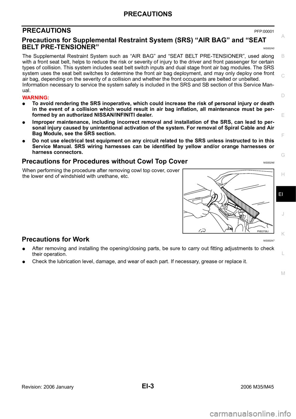
Precautions for Procedures without Cowl Top CoverNIS00246
When performing the procedure after removing cowl top cover, cover
the lower end of windshield with urethane, etc.
Precautions for WorkNIS00247
After removing and installing the opening/closing parts, be sure to carry out fitting adjustments to check
their operation.
Check the lubrication level, damage, and wear of each part. If necessary, grease or replace it.
PIIB3706J
Page 3011 of 5621
EI-6
SQUEAK AND RATTLE TROUBLE DIAGNOSES
Revision: 2006 January2006 M35/M45
DUPLICATE THE NOISE AND TEST DRIVE
If possible, drive the vehicle with the customer until the noise is duplicated. Note any additional information on
the Diagnostic Worksheet regarding the conditions or location of the noise. This information can be used to
duplicate the same conditions when you confirm the repair.
If the noise can be duplicated easily during the test drive, to help identify the source of the noise, try to dupli-
cate the noise with the vehicle stopped by doing one or all of the following:
1) Close a door.
2) Tap or push/pull around the area where the noise appears to be coming from.
3) Rev the engine.
4) Use a floor jack to recreate vehicle “twist”.
5) At idle, apply engine load (electrical load, half-clutch on M/T models, drive position on A/T models).
6) Raise the vehicle on a hoist and hit a tire with a rubber hammer.
Drive the vehicle and attempt to duplicate the conditions the customer states exist when the noise occurs.
If it is difficult to duplicate the noise, drive the vehicle slowly on an undulating or rough road to stress the
vehicle body.
CHECK RELATED SERVICE BULLETINS
After verifying the customer concern or symptom, check ASIST for Technical Service Bulletins (TSBs) related
to that concern or symptom.
If a TSB relates to the symptom, follow the procedure to repair the noise.
LOCATE THE NOISE AND IDENTIFY THE ROOT CAUSE
1. Narrow down the noise to a general area. To help pinpoint the source of the noise, use a listening tool
(Chassis Ear: J-39570, Engine Ear and mechanics stethoscope).
2. Narrow down the noise to a more specific area and identify the cause of the noise by:
removing the components in the area that you suspect the noise is coming from.
Do not use too much force when removing clips and fasteners, otherwise clips and fastener can be broken
or lost during the repair, resulting in the creation of new noise.
tapping or pushing/pulling the component that you suspect is causing the noise.
Do not tap or push/pull the component with excessive force, otherwise the noise will be eliminated only
temporarily.
feeling for a vibration with your hand by touching the component(s) that you suspect is (are) causing the
noise.
placing a piece of paper between components that you suspect are causing the noise.
looking for loose components and contact marks.
Refer to EI-7, "
Generic Squeak and Rattle Troubleshooting" .
REPAIR THE CAUSE
If the cause is a loose component, tighten the component securely.
If the cause is insufficient clearance between components:
–separate components by repositioning or loosening and retightening the component, if possible.
–insulate components with a suitable insulator such as urethane pads, foam blocks, felt cloth tape or ure-
thane tape. A Nissan Squeak and Rattle Kit (J-43980) is available through your authorized Nissan Parts
Department.
CAUTION:
Do not use excessive force as many components are constructed of plastic and may be damaged.
NOTE:
Always check with the Parts Department for the latest parts information.
The following materials are contained in the Nissan Squeak and Rattle Kit (J-43980). Each item can be
ordered separately as needed.
URETHANE PADS [1.5 mm (0.059 in) thick]
Insulates connectors, harness, etc.
76268-9E005: 100
135 mm (3.945.31 in)/76884-71L01: 6085 mm (2.363.35 in)/76884-
71L02: 15
25 mm (0.590.98 in)
INSULATOR (Foam blocks)
Insulates components from contact. Can be used to fill space behind a panel.
73982-9E000: 45 mm (1.77 in) thick, 50
50 mm (1.971.97 in)/73982-
50Y00: 10 mm (0.39 in) thick, 50
50 mm (1.971.97 in)
Page 3012 of 5621
SQUEAK AND RATTLE TROUBLE DIAGNOSES
EI-7
C
D
E
F
G
H
J
K
L
MA
B
EI
Revision: 2006 January2006 M35/M45
INSULATOR (Light foam block)
80845-71L00: 30 mm (1.18 in) thick, 30
50 mm (1.181.97 in)
FELT CLOTHTAPE
Used to insulate where movement does not occur. Ideal for instrument panel applications.
68370-4B000: 15
25 mm (0.590.98 in) pad/68239-13E00: 5 mm (0.20 in) wide tape roll
The following materials, not found in the kit, can also be used to repair squeaks and rattles.
UHMW (TEFLON) TAPE
Insulates where slight movement is present. Ideal for instrument panel applications.
SILICONE GREASE
Used in place of UHMW tape that will be visible or not fit. Will only last a few months.
SILICONE SPRAY
Use when grease cannot be applied.
DUCT TAPE
Use to eliminate movement.
CONFIRM THE REPAIR
Confirm that the cause of a noise is repaired by test driving the vehicle. Operate the vehicle under the same
conditions as when the noise originally occurred. Refer to the notes on the Diagnostic Worksheet.
Generic Squeak and Rattle TroubleshootingNIS0024B
Refer to Table of Contents for specific component removal and installation information.
INSTRUMENT PANEL
Most incidents are caused by contact and movement between:
1. The cluster lid A and instrument panel
2. Acrylic lens and combination meter housing
3. Instrument panel to front pillar garnish
4. Instrument panel to windshield
5. Instrument panel mounting pins
6. Wiring harnesses behind the combination meter
7. A/C defroster duct and duct joint
These incidents can usually be located by tapping or moving the components to duplicate the noise or by
pressing on the components while driving to stop the noise. Most of these incidents can be repaired by
applying felt cloth tape or silicon spray (in hard to reach areas). Urethane pads can be used to insulate
wiring harness.
CAUTION:
Do not use silicone spray to isolate a squeak or rattle. If you saturate the area with silicone, you
will not be able to recheck the repair.
CENTER CONSOLE
Components to pay attention to include:
1. Shifter assembly cover to finisher
2. A/C control unit and cluster lid C
3. Wiring harnesses behind audio and A/C control unit
The instrument panel repair and isolation procedures also apply to the center console.
DOORS
Pay attention to the:
1. Finisher and inner panel making a slapping noise
2. Inside handle escutcheon to door finisher
3. Wiring harnesses tapping
4. Door striker out of alignment causing a popping noise on starts and stops
Tapping or moving the components or pressing on them while driving to duplicate the conditions can isolate
many of these incidents. You can usually insulate the areas with felt cloth tape or insulator foam blocks from
the Nissan Squeak and Rattle Kit (J-43980) to repair the noise.
Page 3046 of 5621
BODY SIDE TRIM
EI-41
C
D
E
F
G
H
J
K
L
MA
B
EI
Revision: 2006 January2006 M35/M45
REAR WHEEL HOUSE GARNISH
Removal
1. Remove rear seat cushion and rear seatback. Refer to SE-176, "Removal and Installation" .
2. Remove rear body side welt.
3. Remove clip of rear wheel house garnish.
4. Remove rear wheel house garnish.
Installation
Install in the reverse order of removal.
NOTE:
To install, check if all clips are matched over holes of panel on vehicle, then push on.
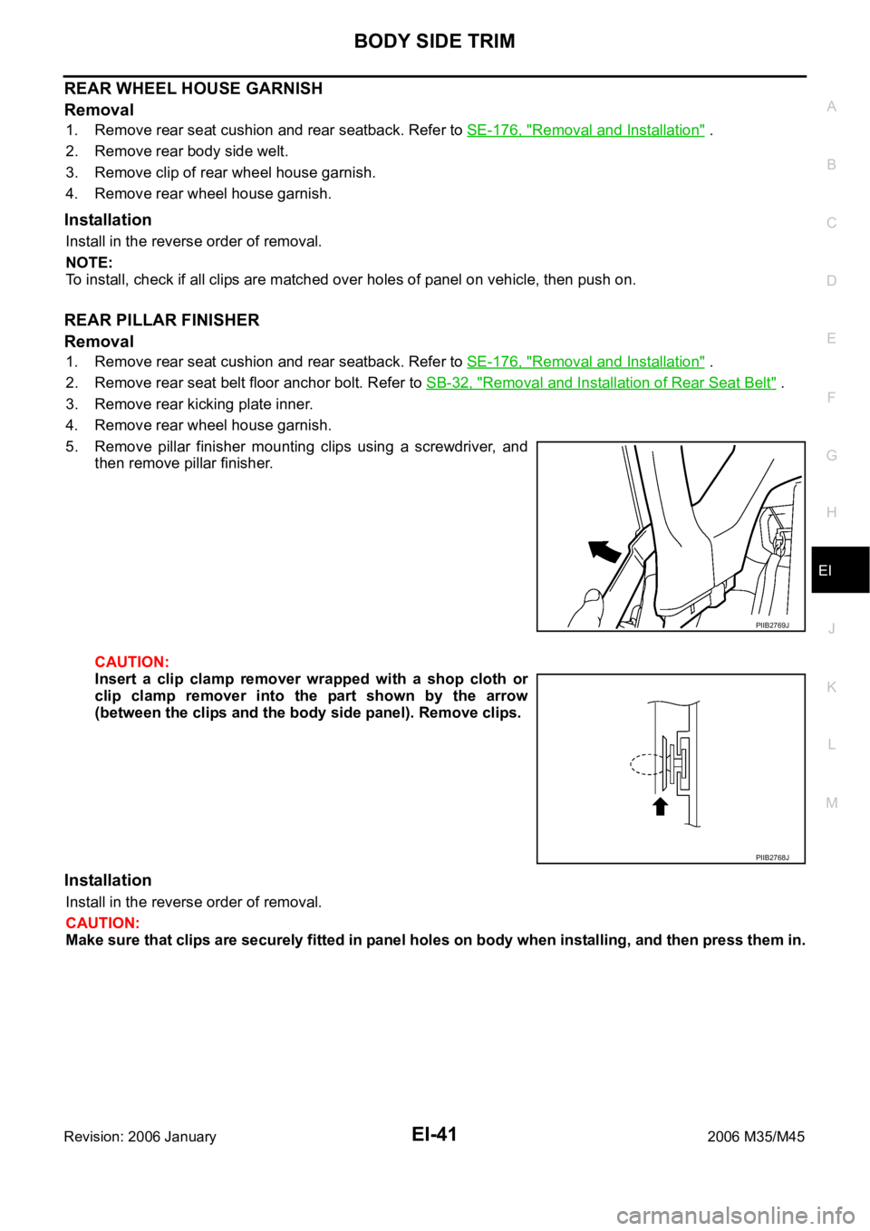
REAR PILLAR FINISHER
Removal
1. Remove rear seat cushion and rear seatback. Refer to SE-176, "Removal and Installation" .
2. Remove rear seat belt floor anchor bolt. Refer to SB-32, "
Removal and Installation of Rear Seat Belt" .
3. Remove rear kicking plate inner.
4. Remove rear wheel house garnish.
5. Remove pillar finisher mounting clips using a screwdriver, and
then remove pillar finisher.
CAUTION:
Insert a clip clamp remover wrapped with a shop cloth or
clip clamp remover into the part shown by the arrow
(between the clips and the body side panel). Remove clips.
Installation
Install in the reverse order of removal.
CAUTION:
Make sure that clips are securely fitted in panel holes on body when installing, and then press them in.
PIIB2769J
PIIB2768J
Page 3064 of 5621
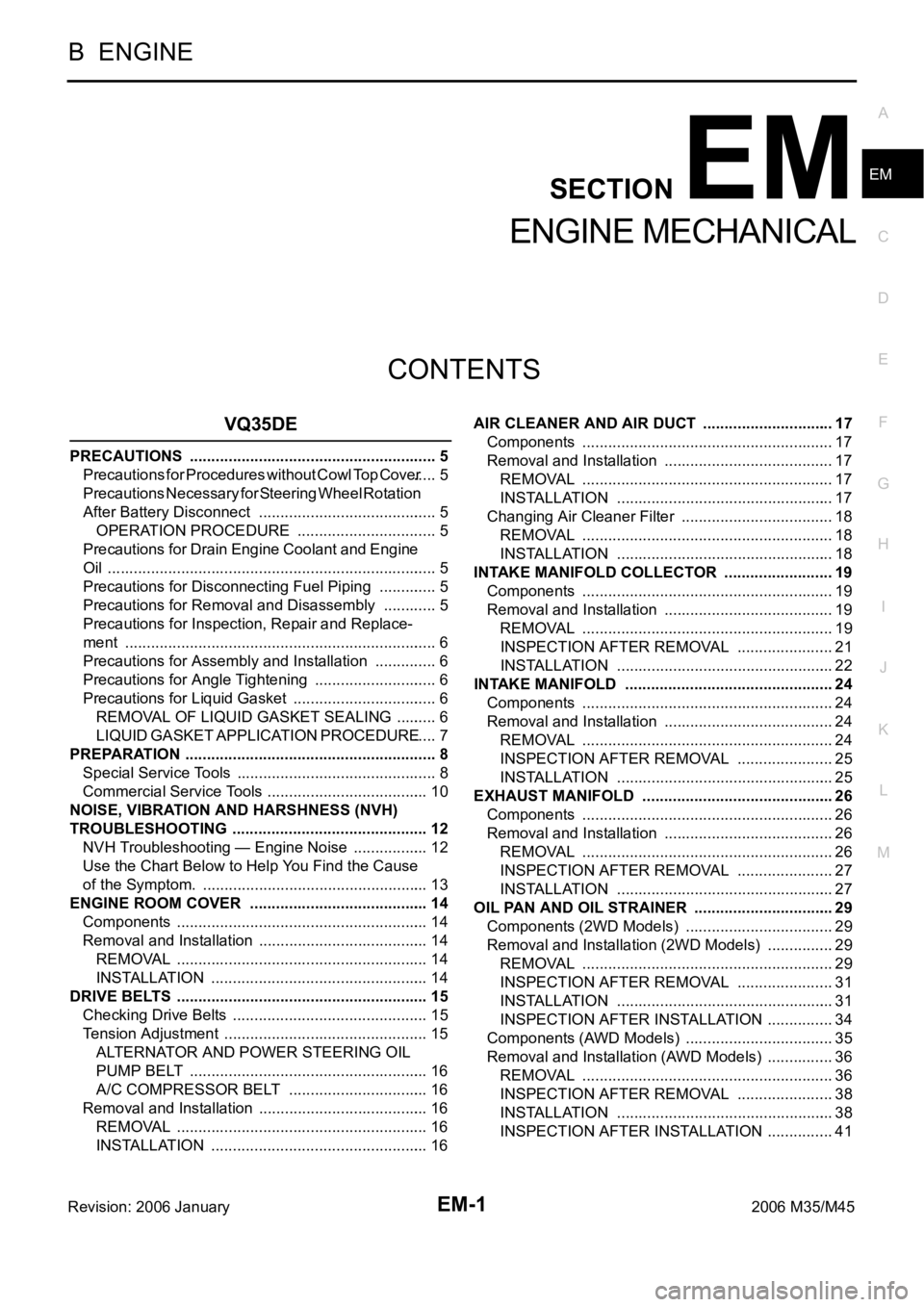
EM-1
ENGINE MECHANICAL
B ENGINE
CONTENTS
C
D
E
F
G
H
I
J
K
L
M
SECTION EM
A
EM
Revision: 2006 January2006 M35/M45
ENGINE MECHANICAL
VQ35DE
PRECAUTIONS .......................................................... 5
Precautions for Procedures without Cowl Top Cover ..... 5
Precautions Necessary for Steering Wheel Rotation
After Battery Disconnect .......................................... 5
OPERATION PROCEDURE ................................. 5
Precautions for Drain Engine Coolant and Engine
Oil ............................................................................. 5
Precautions for Disconnecting Fuel Piping .............. 5
Precautions for Removal and Disassembly ............. 5
Precautions for Inspection, Repair and Replace-
ment ......................................................................... 6
Precautions for Assembly and Installation ............... 6
Precautions for Angle Tightening ............................. 6
Precautions for Liquid Gasket .................................. 6
REMOVAL OF LIQUID GASKET SEALING .......... 6
LIQUID GASKET APPLICATION PROCEDURE ..... 7
PREPARATION ........................................................... 8
Special Service Tools ............................................... 8
Commercial Service Tools ...................................... 10
NOISE, VIBRATION AND HARSHNESS (NVH)
TROUBLESHOOTING .............................................. 12
NVH Troubleshooting — Engine Noise .................. 12
Use the Chart Below to Help You Find the Cause
of the Symptom. ..................................................... 13
ENGINE ROOM COVER .......................................... 14
Components ........................................................... 14
Removal and Installation ........................................ 14
REMOVAL ........................................................
... 14
INSTALLATION ................................................... 14
DRIVE BELTS ........................................................... 15
Checking Drive Belts .............................................. 15
Tension Adjustment ................................................ 15
ALTERNATOR AND POWER STEERING OIL
PUMP BELT ........................................................ 16
A/C COMPRESSOR BELT ................................. 16
Removal and Installation ........................................ 16
REMOVAL ........................................................
... 16
INSTALLATION ................................................... 16AIR CLEANER AND AIR DUCT ............................... 17
Components ........................................................... 17
Removal and Installation ........................................ 17
REMOVAL ........................................................
... 17
INSTALLATION ................................................... 17
Changing Air Cleaner Filter .................................... 18
REMOVAL ........................................................
... 18
INSTALLATION ................................................... 18
INTAKE MANIFOLD COLLECTOR .......................... 19
Components ........................................................... 19
Removal and Installation ........................................ 19
REMOVAL ........................................................
... 19
INSPECTION AFTER REMOVAL ....................... 21
INSTALLATION ................................................... 22
INTAKE MANIFOLD ................................................. 24
Components ........................................................... 24
Removal and Installation ........................................ 24
REMOVAL ........................................................
... 24
INSPECTION AFTER REMOVAL ....................... 25
INSTALLATION ................................................... 25
EXHAUST MANIFOLD ............................................. 26
Components ........................................................... 26
Removal and Installation ........................................ 26
REMOVAL ........................................................
... 26
INSPECTION AFTER REMOVAL ....................... 27
INSTALLATION ................................................... 27
OIL PAN AND OIL STRAINER ................................. 29
Components (2WD Models) ................................... 29
Removal and Installation (2WD Models) ................ 29
REMOVAL ........................................................
... 29
INSPECTION AFTER REMOVAL ....................... 31
INSTALLATION ................................................... 31
INSPECTION AFTER INSTALLATION ................ 34
Components (AWD Models) ................................... 35
Removal and Installation (AWD Models) ................ 36
REMOVAL ........................................................
... 36
INSPECTION AFTER REMOVAL ....................... 38
INSTALLATION ................................................... 38
INSPECTION AFTER INSTALLATION ................ 41
Page 3065 of 5621
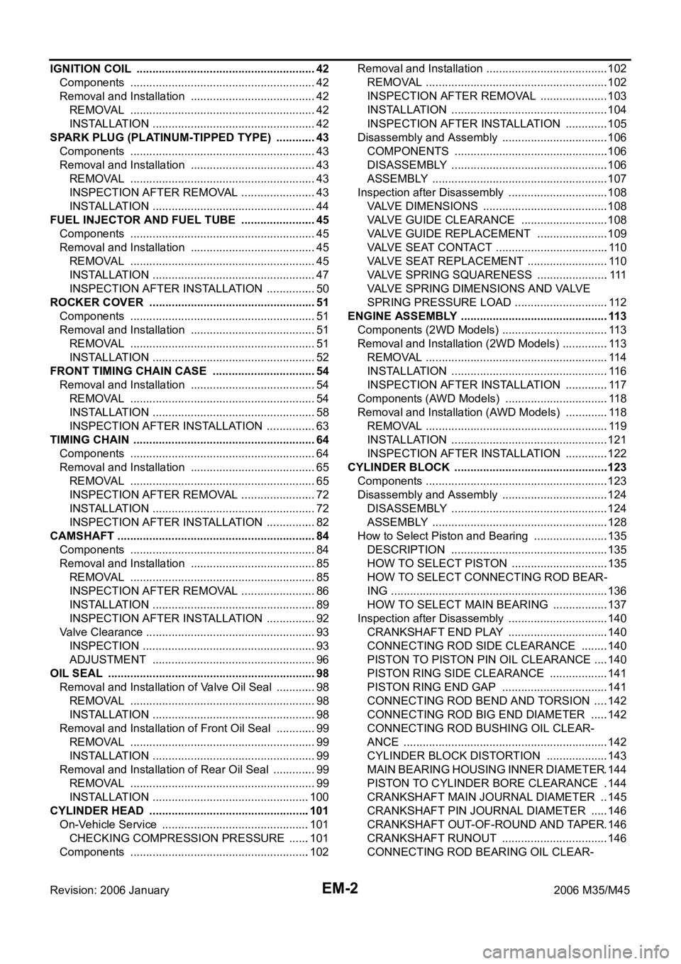
EM-2Revision: 2006 January2006 M35/M45 IGNITION COIL ......................................................... 42
Components ........................................................... 42
Removal and Installation ........................................ 42
REMOVAL ........................................................
... 42
INSTALLATION .................................................... 42
SPARK PLUG (PLATINUM-TIPPED TYPE) ............. 43
Components ........................................................... 43
Removal and Installation ........................................ 43
REMOVAL ........................................................
... 43
INSPECTION AFTER REMOVAL ........................ 43
INSTALLATION .................................................... 44
FUEL INJECTOR AND FUEL TUBE ........................ 45
Components ........................................................... 45
Removal and Installation ........................................ 45
REMOVAL ........................................................
... 45
INSTALLATION .................................................... 47
INSPECTION AFTER INSTALLATION ................ 50
ROCKER COVER ..................................................... 51
Components ........................................................... 51
Removal and Installation ........................................ 51
REMOVAL ........................................................
... 51
INSTALLATION .................................................... 52
FRONT TIMING CHAIN CASE ................................. 54
Removal and Installation ........................................ 54
REMOVAL ........................................................
... 54
INSTALLATION .................................................... 58
INSPECTION AFTER INSTALLATION ................ 63
TIMING CHAIN .......................................................... 64
Components ........................................................... 64
Removal and Installation ........................................ 65
REMOVAL ........................................................
... 65
INSPECTION AFTER REMOVAL ........................ 72
INSTALLATION .................................................... 72
INSPECTION AFTER INSTALLATION ................ 82
CAMSHAFT ............................................................... 84
Components ........................................................... 84
Removal and Installation ........................................ 85
REMOVAL ........................................................
... 85
INSPECTION AFTER REMOVAL ........................ 86
INSTALLATION .................................................... 89
INSPECTION AFTER INSTALLATION ................ 92
Valve Clearance ...................................................... 93
INSPECTION ....................................................... 93
ADJUSTMENT .................................................... 96
OIL SEAL ......................................................
............ 98
Removal and Installation of Valve Oil Seal ............. 98
REMOVAL ........................................................
... 98
INSTALLATION .................................................... 98
Removal and Installation of Front Oil Seal ............. 99
REMOVAL ........................................................
... 99
INSTALLATION .................................................... 99
Removal and Installation of Rear Oil Seal .............. 99
REMOVAL ........................................................
... 99
INSTALLATION ..................................................100
CYLINDER HEAD .................................................. .101
On-Vehicle Service ...............................................101
CHECKING COMPRESSION PRESSURE .......101
Components .........................................................102Removal and Installation .......................................102
REMOVAL ..........................................................102
INSPECTION AFTER REMOVAL ......................103
INSTALLATION ..................................................104
INSPECTION AFTER INSTALLATION ..............105
Disassembly and Assembly ..................................106
COMPONENTS .................................................106
DISASSEMBLY ..................................................106
ASSEMBLY ........................................................107
Inspection after Disassembly ................................108
VALVE DIMENSIONS ........................................108
VALVE GUIDE CLEARANCE ............................108
VALVE GUIDE REPLACEMENT .......................109
VALVE SEAT CONTACT ....................................110
VALVE SEAT REPLACEMENT ..........................110
VALVE SPRING SQUARENESS ....................... 111
VALVE SPRING DIMENSIONS AND VALVE
SPRING PRESSURE LOAD ..............................112
ENGINE ASSEMBLY ...............................................113
Components (2WD Models) ..................................113
Removal and Installation (2WD Models) ...............113
REMOVAL ..........................................................114
INSTALLATION ..................................................116
INSPECTION AFTER INSTALLATION ..............117
Components (AWD Models) .................................118
Removal and Installation (AWD Models) ..............118
REMOVAL ..........................................................119
INSTALLATION ..................................................121
INSPECTION AFTER INSTALLATION ..............122
CYLINDER BLOCK .................................................123
Components ..........................................................123
Disassembly and Assembly ..................................124
DISASSEMBLY ..................................................124
ASSEMBLY ......................................................
..128
How to Select Piston and Bearing ........................135
DESCRIPTION ..................................................135
HOW TO SELECT PISTON ...............................135
HOW TO SELECT CONNECTING ROD BEAR-
ING .....................................................................136
HOW TO SELECT MAIN BEARING ..................137
Inspection after Disassembly ................................140
CRANKSHAFT END PLAY ................................140
CONNECTING ROD SIDE CLEARANCE .........140
PISTON TO PISTON PIN OIL CLEARANCE .....140
PISTON RING SIDE CLEARANCE ...................141
PISTON RING END GAP ..................................141
CONNECTING ROD BEND AND TORSION .....142
CONNECTING ROD BIG END DIAMETER ......142
CONNECTING ROD BUSHING OIL CLEAR-
ANCE .................................................................142
CYLINDER BLOCK DISTORTION ....................143
MAIN BEARING HOUSING INNER DIAMETER .144
PISTON TO CYLINDER BORE CLEARANCE ..144
CRANKSHAFT MAIN JOURNAL DIAMETER ...145
CRANKSHAFT PIN JOURNAL DIAMETER ......146
CRANKSHAFT OUT-OF-ROUND AND TAPER .146
CRANKSHAFT RUNOUT ..................................146
CONNECTING ROD BEARING OIL CLEAR-
Page 3066 of 5621
EM-3
C
D
E
F
G
H
I
J
K
L
M
EMA
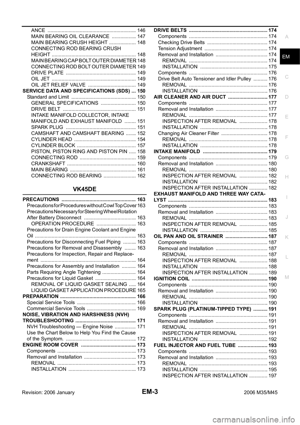
Revision: 2006 January2006 M35/M45 ANCE ................................................................146
MAIN BEARING OIL CLEARANCE ..................147
MAIN BEARING CRUSH HEIGHT ....................148
CONNECTING ROD BEARING CRUSH
HEIGHT .............................................................148
MAIN BEARING CAP BOLT OUTER DIAMETER .148
CONNECTING ROD BOLT OUTER DIAMETER .149
DRIVE PLATE ...................................................149
OIL JET .............................................................149
OIL JET RELIEF VALVE ...................................149
SERVICE DATA AND SPECIFICATIONS (SDS) ....150
Standard and Limit ...............................................150
GENERAL SPECIFICATIONS ..........................150
DRIVE BELT .....................................................151
INTAKE MANIFOLD COLLECTOR, INTAKE
MANIFOLD AND EXHAUST MANIFOLD .........151
SPARK PLUG ...................................................151
CAMSHAFT AND CAMSHAFT BEARING ........152
CYLINDER HEAD .............................................154
CYLINDER BLOCK ...........................................157
PISTON, PISTON RING AND PISTON PIN ......158
CONNECTING ROD .........................................159
CRANKSHAFT ..................................................160
MAIN BEARING ................................................161
CONNECTING ROD BEARING ........................162
VK45DE
PRECAUTIONS ......................................................163
Precautions for Procedures without Cowl Top Cover .163
Precautions Necessary for Steering Wheel Rotation
After Battery Disconnect ......................................163
OPERATION PROCEDURE .............................163
Precautions for Drain Engine Coolant and Engine
Oil .........................................................................163
Precautions for Disconnecting Fuel Piping ..........163
Precautions for Removal and Disassembly .........163
Precautions for Inspection, Repair and Replace-
ment .....................................................................164
Precautions for Assembly and Installation ...........164
Parts Requiring Angle Tightening .........................164
Precautions for Liquid Gasket ..............................164
REMOVAL OF LIQUID GASKET SEALING ......164
LIQUID GASKET APPLICATION PROCEDURE .165
PREPARATION .......................................................166
Special Service Tools ...........................................166
Commercial Service Tools ....................................169
NOISE, VIBRATION AND HARSHNESS (NVH)
TROUBLESHOOTING ............................................171
NVH Troubleshooting — Engine Noise ................171
Use the Chart Below to Help You Find the Cause
of the Symptom. ...................................................172
ENGINE ROOM COVER ........................................173
Components .........................................................173
Removal and Installation ......................................173
REMOVAL ........................................................
.173
INSTALLATION .................................................173DRIVE BELTS .........................................................174
Components .........................................................174
Checking Drive Belts ............................................174
Tension Adjustment .............................................
.174
Removal and Installation ......................................174
REMOVAL ........................................................
.174
INSTALLATION .................................................175
Components .........................................................176
Drive Belt Auto Tensioner and Idler Pulley ...........176
REMOVAL ........................................................
.176
INSTALLATION .................................................176
AIR CLEANER AND AIR DUCT .............................177
Components .........................................................177
Removal and Installation ......................................177
REMOVAL ........................................................
.177
INSPECTION AFTER REMOVAL .....................178
INSTALLATION .................................................178
Changing Air Cleaner Filter ..................................178
REMOVAL ........................................................
.178
INSTALLATION .................................................178
INTAKE MANIFOLD ..............................................
.179
Components .........................................................179
Removal and Installation ......................................180
REMOVAL ........................................................
.180
INSPECTION AFTER REMOVAL .....................182
INSTALLATION .................................................182
INSPECTION AFTER INSTALLATION ..............182
EXHAUST MANIFOLD AND THREE WAY CATA-
LYST ........................................................................183
Components .........................................................183
Removal and Installation ......................................183
REMOVAL ........................................................
.183
INSPECTION AFTER REMOVAL .....................185
INSTALLATION .................................................185
OIL PAN AND OIL STRAINER ...............................187
Components .........................................................187
Removal and Installation ......................................187
REMOVAL ........................................................
.187
INSPECTION AFTER REMOVAL .....................188
INSTALLATION .................................................188
INSPECTION AFTER INSTALLATION ..............189
IGNITION COIL .......................................................190
Components .........................................................190
Removal and Installation ......................................190
REMOVAL ........................................................
.190
INSTALLATION .................................................190
SPARK PLUG (PLATINUM-TIPPED TYPE) ...........191
Components .........................................................191
Removal and Installation ......................................191
REMOVAL ........................................................
.191
INSPECTION AFTER REMOVAL .....................191
INSTALLATION .................................................192
FUEL INJECTOR AND FUEL TUBE ......................193
Components .........................................................193
Removal and Installation ......................................193
REMOVAL ........................................................
.193
INSTALLATION .................................................195
INSPECTION AFTER INSTALLATION ..............197
Page 3067 of 5621
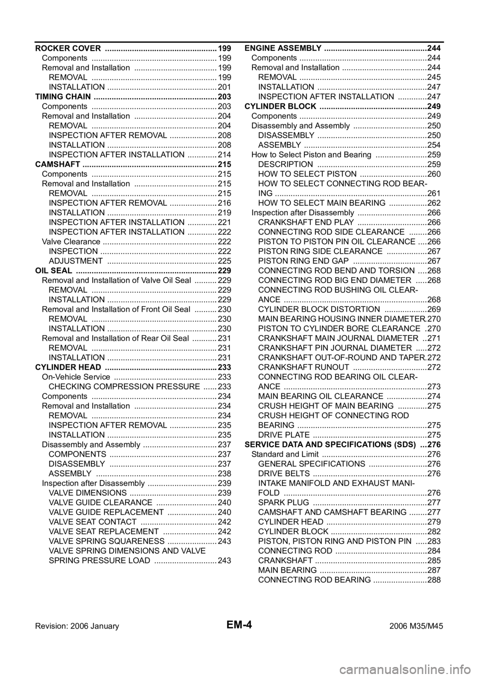
EM-4Revision: 2006 January2006 M35/M45 ROCKER COVER ...................................................199
Components .........................................................199
Removal and Installation ......................................199
REMOVAL ........................................................
.199
INSTALLATION ..................................................201
TIMING CHAIN ........................................................203
Components .........................................................203
Removal and Installation ......................................204
REMOVAL ........................................................
.204
INSPECTION AFTER REMOVAL ......................208
INSTALLATION ..................................................208
INSPECTION AFTER INSTALLATION ..............214
CAMSHAFT .............................................................215
Components .........................................................215
Removal and Installation ......................................215
REMOVAL ........................................................
.215
INSPECTION AFTER REMOVAL ......................216
INSTALLATION ..................................................219
INSPECTION AFTER INSTALLATION ..............221
INSPECTION AFTER INSTALLATION ..............222
Valve Clearance ....................................................222
INSPECTION .....................................................222
ADJUSTMENT ..................................................225
OIL SEAL ................................................................229
Removal and Installation of Valve Oil Seal ...........229
REMOVAL ........................................................
.229
INSTALLATION ..................................................229
Removal and Installation of Front Oil Seal ...........230
REMOVAL ........................................................
.230
INSTALLATION ..................................................230
Removal and Installation of Rear Oil Seal ............231
REMOVAL ........................................................
.231
INSTALLATION ..................................................231
CYLINDER HEAD .................................................. .233
On-Vehicle Service ...............................................233
CHECKING COMPRESSION PRESSURE .......233
Components .........................................................234
Removal and Installation ......................................234
REMOVAL ........................................................
.234
INSPECTION AFTER REMOVAL ......................235
INSTALLATION ..................................................235
Disassembly and Assembly ..................................237
COMPONENTS .................................................237
DISASSEMBLY .................................................237
ASSEMBLY ......................................................
.238
Inspection after Disassembly ................................239
VALVE DIMENSIONS ........................................239
VALVE GUIDE CLEARANCE ............................240
VALVE GUIDE REPLACEMENT .......................240
VALVE SEAT CONTACT ...................................242
VALVE SEAT REPLACEMENT .........................242
VALVE SPRING SQUARENESS .......................243
VALVE SPRING DIMENSIONS AND VALVE
SPRING PRESSURE LOAD .............................243ENGINE ASSEMBLY ...............................................244
Components ..........................................................244
Removal and Installation .......................................244
REMOVAL ..........................................................245
INSTALLATION ..................................................247
INSPECTION AFTER INSTALLATION ..............247
CYLINDER BLOCK .................................................249
Components ..........................................................249
Disassembly and Assembly ..................................250
DISASSEMBLY ..................................................250
ASSEMBLY ........................................................254
How to Select Piston and Bearing ........................259
DESCRIPTION ..................................................259
HOW TO SELECT PISTON ...............................260
HOW TO SELECT CONNECTING ROD BEAR-
ING .....................................................................261
HOW TO SELECT MAIN BEARING ..................262
Inspection after Disassembly ................................266
CRANKSHAFT END PLAY ................................266
CONNECTING ROD SIDE CLEARANCE .........266
PISTON TO PISTON PIN OIL CLEARANCE .....266
PISTON RING SIDE CLEARANCE ...................267
PISTON RING END GAP ..................................267
CONNECTING ROD BEND AND TORSION .....268
CONNECTING ROD BIG END DIAMETER ......268
CONNECTING ROD BUSHING OIL CLEAR-
ANCE .................................................................268
CYLINDER BLOCK DISTORTION ....................269
MAIN BEARING HOUSING INNER DIAMETER .270
PISTON TO CYLINDER BORE CLEARANCE ..270
CRANKSHAFT MAIN JOURNAL DIAMETER ...271
CRANKSHAFT PIN JOURNAL DIAMETER ......272
CRANKSHAFT OUT-OF-ROUND AND TAPER .272
CRANKSHAFT RUNOUT ..................................272
CONNECTING ROD BEARING OIL CLEAR-
ANCE .................................................................273
MAIN BEARING OIL CLEARANCE ...................274
CRUSH HEIGHT OF MAIN BEARING ..............275
CRUSH HEIGHT OF CONNECTING ROD
BEARING ...........................................................275
DRIVE PLATE ....................................................275
SERVICE DATA AND SPECIFICATIONS (SDS) ....276
Standard and Limit ................................................276
GENERAL SPECIFICATIONS ...........................276
DRIVE BELTS ....................................................276
INTAKE MANIFOLD AND EXHAUST MANI-
FOLD .................................................................276
SPARK PLUG ....................................................277
CAMSHAFT AND CAMSHAFT BEARING .........277
CYLINDER HEAD ..............................................279
CYLINDER BLOCK ............................................282
PISTON, PISTON RING AND PISTON PIN ......283
CONNECTING ROD ..........................................284
CRANKSHAFT ...................................................285
MAIN BEARING .................................................287
CONNECTING ROD BEARING .........................288