2006 INFINITI M35 starting
[x] Cancel search: startingPage 4864 of 5621

PDU (POWER DISTRIBUTION UNIT)
PG-37
C
D
E
F
G
H
I
J
L
MA
B
PG
Revision: 2006 January2006 M35/M45
Terminals and Reference Value for Intelligent Key UnitNKS004EG
Te r m i -
nalWire
ColorItemCondition
Voltage (V)
Approx. Ignition
Switch
PositionOperation or Conditions
1 SB Power source (Fuse) LOCK — Battery voltage
3 Y IPDM E/R status signal —Engine starting (During Cranking) 5
Other than above 2
8WPush-button ignition
switch
(LOCK LED)LOCK Push-button ignition switch is in LOCK position 0
—Push-button ignition switch is in any position
(Except LOCK position)1.2
9LPush-button ignition
switch
(ACC LED)ACC Push-button ignition switch is in ACC position 0
—Push-button ignition switch is in any position
(Except ACC position)1.2
10 VPush-button ignition
switch
(ON LED)ON Push-button ignition switch is in ON position 0
—Push-button ignition switch is in any position
(Except ON position)1.2
20 B Ground — — 0
30 L/W Ignition switch (ACC) ACC — Battery voltage
31 GR Ignition switch (ON) ON — Battery voltage
34 R PDU feedback signal LOCKPush-button ignition switch is in LOCK state, 30 sec-
onds after all doors closed1
Other than above 0
36 W Ignition signal 2LOCK — Battery voltage
ACC — Battery voltage
ON — 0
37 P CAN-L — — —
38 L CAN-H — — —
39 BR/W Push switch —Depress push-button ignition switch 0
Unpress push-button ignition switch Battery voltage
40 B Ground — — 0
41 Y Power source (Fuse) LOCK — Battery voltage
42 P PDU wake up signal LOCKPush-button ignition switch is in LOCk state, 30 sec-
onds after all doors closedBattery voltage
Other than above 0
44 BR Ignition signal 1LOCK — Battery voltage
ACC — Battery voltage
ON — 0
45 SB ACC signalLOCK — Battery voltage
ACC — 0
ON — 0
56 B Ground — — 0
57 L Power source (Fuse) LOCK — Battery voltage
72 B Ground — — 0
Page 4865 of 5621

PG-38
PDU (POWER DISTRIBUTION UNIT)
Revision: 2006 January2006 M35/M45
Terminals and Reference Value for PDUNKS004EH
Work FlowNKS004EI
1. Check the symptom and customer's requests.
2. Understand outline of system. Refer to PG-33, "
System Description" .
3. Confirm that Intelligent Key system operates normally.
Refer to BL-24, "
POWER DOOR LOCK SYSTEM" .
4. Repair or replace any malfunctioning parts.
Refer to PG-39, "
Trouble Diagnosis Symptom Chart" .
5. INSPECTION END
Te r m i -
nalWire
ColorItemCondition
Voltage (V)
Approx. Ignition
Switch
PositionOperation or Conditions
1 P PDU wake up signal LOCKPush-button ignition switch is in LOCK state, 30 sec-
onds after all doors closeBattery voltage
Other than above 0
4 BR Ignition signal 1LOCK — Battery voltage
ACC — Battery voltage
ON — 0
5 W Ignition signal 2LOCK — Battery voltage
ACC — Battery voltage
ON — 0
8 SB ACC signalLOCK — Battery voltage
ACC — 0
ON — 0
10 B Ground — — 0
11 Y IPDM E/R status signal —Engine starting (During Cranking) 5
Other than above 2
12 R PDU feedback signal LOCKPush-button ignition switch is in LOCK state, 30 sec-
onds after all doors close1
Other than above 0
14 SB Power source (Fuse) LOCK — Battery voltage
15 L Power source (F/L) LOCK — Battery voltage
16 W ACC power outputLOCK — 0
ACC — Battery voltage
ON — Battery voltage
17 G Power source (Fuse) LOCK — Battery voltage
18 BR ON power outputLOCK — 0
ACC — 0
ON — Battery voltage
Page 4922 of 5621

HARNESS
PG-95
C
D
E
F
G
H
I
J
L
MA
B
PG
Revision: 2006 January2006 M35/M45
PGC/V EC EVAP Canister Purge Volume Control Solenoid Valve
PHASE EC Camshaft Position Sensor (PHASE)
PHSB1 EC Camshaft Position Sensor (PHASE) (Bank 1)
PHSB2 EC Camshaft Position Sensor (PHASE) (Bank 2)
PNP/SW AT Park/Neutral Position Switch
PNP/SW EC Park/Neutral Position Switch
POS EC Crankshaft Position Sensor (CKPS) (POS)
POWER PG Power Supply Routing Circuit
PRE/SE EC EVAP Control System Pressure Sensor
PS/SEN EC Power Steering Pressure Sensor
PSB SB Pre-Crash Seat Belt
R/SEAT SE Auto Return Seat
RAS STC Rear Active Steer
ROOM/L LT Interior Room Lamp
RP/SEN EC Refrigerant Pressure Sensor
SEAT SE Power Seat
SEN/PW EC Sensor Power Supply
SHADE EI Rear Sunshade
SHIFT AT A/T Shift Lock System
SNOWSW EC Snow Mode Switch
SROOF RF Sunroof
SRS SRS Supplemental Restraint System
START SC Starting System
STOP/L LT Stop Lamp
STSIG AT Start Signal Circuit
T/WARN WT Low Tire Pressure Warning System
TAIL/L LT Parking, License and Tail Lamps
TLID BL Trunk Lid Opener
TPS1 EC Throttle Position Sensor (Sensor 1)
TPS2 EC Throttle Position Sensor (Sensor 2)
TPS3 EC Throttle Position Sensor
TRNSCV BL Homelink Universal Transceiver
TURN LT Turn Signal and Hazard Warning Lamp
VDC BRC Vehicle Dynamics Control System
VEHSEC BL Vehicle Security System
VENT/V EC EVAP Canister Vent Control Valve
VIAS EC Variable Induction Air Control System
VIAS/V EC VIAS Control Solenoid Valve
VSSA/T AT Vehicle speed Sensor A/T (Revolution Sensor)
WARN DI Warning Lamps
WINDOW GW Power Window
WIPER WW Front Wiper and Washer Code Section Wiring Diagram Name
Page 4956 of 5621

PRECAUTIONS
PS-3
C
D
E
F
H
I
J
K
L
MA
B
PS
Revision: 2006 January2006 M35/M45
PRECAUTIONSPFP:00001
Precautions for Supplemental Restraint System (SRS) “AIR BAG” and “SEAT
BELT PRE-TENSIONER”
NGS000CZ
The Supplemental Restraint System such as “AIR BAG” and “SEAT BELT PRE-TENSIONER”, used along
with a front seat belt, helps to reduce the risk or severity of injury to the driver and front passenger for certain
types of collision. This system includes seat belt switch inputs and dual stage front air bag modules. The SRS
system uses the seat belt switches to determine the front air bag deployment, and may only deploy one front
air bag, depending on the severity of a collision and whether the front occupants are belted or unbelted.
Information necessary to service the system safely is included in the SRS and SB section of this Service Man-
ual.
WAR NING :
To avoid rendering the SRS inoperative, which could increase the risk of personal injury or death
in the event of a collision which would result in air bag inflation, all maintenance must be per-
formed by an authorized NISSAN/INFINITI dealer.
Improper maintenance, including incorrect removal and installation of the SRS, can lead to per-
sonal injury caused by unintentional activation of the system. For removal of Spiral Cable and Air
Bag Module, see the SRS section.
Do not use electrical test equipment on any circuit related to the SRS unless instructed to in this
Service Manual. SRS wiring harnesses can be identified by yellow and/or orange harnesses or
harness connectors.
Precautions Necessary for Steering Wheel Rotation after Battery DisconnectNGS000D0
NOTE:
Before removing and installing any control units, first turn the push-button ignition switch to the LOCK
position, then disconnect both battery cables.
After finishing work, confirm that all control unit connectors are connected properly, then re-connect both
battery cables.
Always use CONSULT-II to perform self-diagnosis as a part of each function inspection after finishing
work. If a DTC is detected, perform trouble diagnosis according to self-diagnosis results.
This vehicle is equipped with a push-button ignition switch and a steering lock unit.
If the battery is disconnected or discharged, the steering wheel will lock and cannot be turned.
If turning the steering wheel is required with the battery disconnected or discharged, follow the procedure
below before starting the repair operation.
OPERATION PROCEDURE
1. Connect both battery cables.
NOTE:
Supply power using jumper cables if battery is discharged.
2. Carry the Intelligent Key or insert it to the key slot and turn the push-button ignition switch to ACC position.
(At this time, the steering lock will be released.)
3. Disconnect both battery cables. The steering lock will remain released with both battery cables discon-
nected and the steering wheel can be turned.
4. Perform the necessary repair operation.
5. When the repair work is completed, re-connect both battery cables. With the brake pedal released, turn
the push-button ignition switch from ACC position to ON position, then to LOCK position. (The steering
wheel will lock when the push-button ignition switch is turned to LOCK position.)
6. Perform self-diagnosis check of all control units using CONSULT-II.
Page 4982 of 5621

POWER STEERING OIL PUMP
PS-29
C
D
E
F
H
I
J
K
L
MA
B
PS
Revision: 2006 January2006 M35/M45
POWER STEERING OIL PUMPPFP:49110
On-Vehicle Inspection and ServiceNGS000DE
CHECKING RELIEF OIL PRESSURE
CAUTION:
Make sure that belt tension is normal before starting the following procedure.
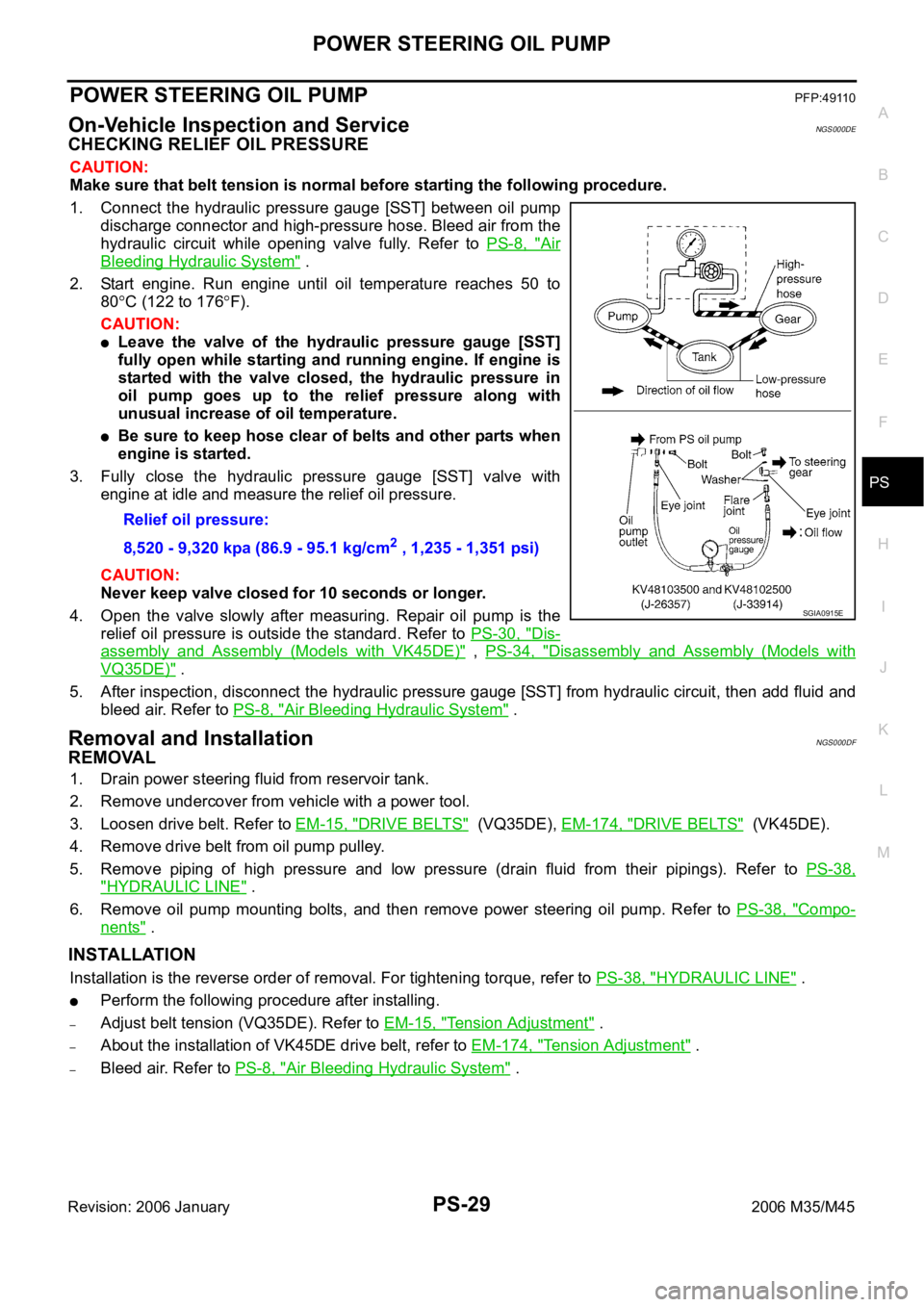
1. Connect the hydraulic pressure gauge [SST] between oil pump
discharge connector and high-pressure hose. Bleed air from the
hydraulic circuit while opening valve fully. Refer to PS-8, "
Air
Bleeding Hydraulic System" .
2. Start engine. Run engine until oil temperature reaches 50 to
80
C (122 to 176F).
CAUTION:
Leave the valve of the hydraulic pressure gauge [SST]
fully open while starting and running engine. If engine is
started with the valve closed, the hydraulic pressure in
oil pump goes up to the relief pressure along with
unusual increase of oil temperature.
Be sure to keep hose clear of belts and other parts when
engine is started.
3. Fully close the hydraulic pressure gauge [SST] valve with
engine at idle and measure the relief oil pressure.
CAUTION:
Never keep valve closed for 10 seconds or longer.
4. Open the valve slowly after measuring. Repair oil pump is the
relief oil pressure is outside the standard. Refer to PS-30, "
Dis-
assembly and Assembly (Models with VK45DE)" , PS-34, "Disassembly and Assembly (Models with
VQ35DE)" .
5. After inspection, disconnect the hydraulic pressure gauge [SST] from hydraulic circuit, then add fluid and
bleed air. Refer to PS-8, "
Air Bleeding Hydraulic System" .
Removal and InstallationNGS000DF
REMOVAL
1. Drain power steering fluid from reservoir tank.
2. Remove undercover from vehicle with a power tool.
3. Loosen drive belt. Refer to EM-15, "
DRIVE BELTS" (VQ35DE), EM-174, "DRIVE BELTS" (VK45DE).
4. Remove drive belt from oil pump pulley.
5. Remove piping of high pressure and low pressure (drain fluid from their pipings). Refer to PS-38,
"HYDRAULIC LINE" .
6. Remove oil pump mounting bolts, and then remove power steering oil pump. Refer to PS-38, "
Compo-
nents" .
INSTALLATION
Installation is the reverse order of removal. For tightening torque, refer to PS-38, "HYDRAULIC LINE" .
Perform the following procedure after installing.
–Adjust belt tension (VQ35DE). Refer to EM-15, "Tension Adjustment" .
–About the installation of VK45DE drive belt, refer to EM-174, "Tension Adjustment" .
–Bleed air. Refer to PS-8, "Air Bleeding Hydraulic System" . Relief oil pressure:
8,520 - 9,320 kpa (86.9 - 95.1 kg/cm
2 , 1,235 - 1,351 psi)
SGIA0915E
Page 5138 of 5621

SC-1
STARTING & CHARGING SYSTEM
K ELECTRICAL
CONTENTS
C
D
E
F
G
H
I
J
L
M
SECTION SC
A
B
SC
Revision: 2006 January2006 M35/M45
STARTING & CHARGING SYSTEM
PRECAUTIONS .......................................................... 2
Precautions for Supplemental Restraint System
(SRS) “AIR BAG” and “SEAT BELT PRE-TEN-
SIONER” .................................................................. 2
Precautions for Power Generation Voltage Variable
Control System ......................................................... 2
PREPARATION ........................................................... 3
Special Service Tools ............................................... 3
Commercial Service Tools ........................................ 3
BATTERY .................................................................... 4
How to Handle Battery ............................................. 4
METHODS OF PREVENTING OVER-DIS-
CHARGE ............................................................... 4
CHECKING ELECTROLYTE LEVEL .................... 5
SPECIFIC GRAVITY CHECK ............................... 5
CHARGING THE BATTERY ................................. 6
Trouble Diagnosis with Battery/Starting/Charging
System Tester (Battery) ............................................ 7
DIAGNOSTIC RESULT ITEM CHART .................. 8
Removal and Installation .......................................... 9
REMOVAL ........................................................
..... 9
INSTALLATION ..................................................... 9
STARTING SYSTEM ................................................ 10
System Description ................................................ 10
Wiring Diagram — START — .................................. 11
VQ35DE ENGINE MODELS ................................ 11
VK45DE ENGINE MODELS ............................... 12
Trouble Diagnosis with Battery/Starting/Charging
System Tester (Starting) ......................................... 13
DIAGNOSTIC RESULT ITEM CHART ................ 13
WORK FLOW ...................................................... 14
DIAGNOSTIC PROCEDURE 1 ........................... 15
DIAGNOSTIC PROCEDURE 2 ........................... 16
MINIMUM SPECIFICATION OF CRANKING
VOLTAGE REFERENCING COOLANT TEM-
PERATURE ......................................................... 16
Removal and Installation ........................................ 17
VQ35DE ENGINE MODELS (2WD) .................... 17VQ35DE ENGINE MODELS (AWD) .................... 18
VK45DE ENGINE MODELS ................................ 19
Disassembly and Assembly .................................... 20
VQ35DE ENGINE MODELS (2WD) .................... 20
VQ35DE ENGINE MODELS (AWD) .................... 21
VK45DE ENGINE MODELS ................................ 22
INSPECTION AFTER DISASSEMBLY ................ 22
CHARGING SYSTEM ............................................... 23
System Description ................................................. 23
DESCRIPTION .................................................... 23
MALFUNCTION INDICATOR .............................. 23
POWER GENERATION VOLTAGE VARIABLE
CONTROL SYSTEM ........................................... 24
Wiring Diagram — CHARGE — ............................. 25
VQ35DE ENGINE MODELS (2WD) .................... 25
VQ35DE ENGINE MODELS (AWD) .................... 26
VK45DE ENGINE MODELS .............................
... 27
Trouble Diagnoses with Battery/Starting/Charging
System Tester (Charging) ....................................... 28
DIAGNOSTIC RESULT ITEM CHART ................ 30
WORK FLOW ...................................................... 31
PRELIMINARY INSPECTION ............................. 32
DIAGNOSTIC PROCEDURE 1 ........................... 32
DIAGNOSTIC PROCEDURE 2 ........................... 33
DIAGNOSTIC PROCEDURE 3 ........................... 33
DIAGNOSTIC PROCEDURE 4 ........................... 34
Power Generation Voltage Variable Control System
Operation Inspection .............................................. 35
Removal and Installation ........................................ 37
VQ35DE ENGINE MODELS ............................... 37
VK45DE ENGINE MODELS ................................ 39
Disassembly and Assembly .................................... 41
VQ35DE ENGINE MODELS ............................... 41
VK45DE ENGINE MODELS ................................ 42
SERVICE DATA AND SPECIFICATIONS (SDS) ...... 43
Battery .................................................................... 43
Starter ..................................................................... 43
Alternator ................................................................ 43
Page 5140 of 5621

PREPARATION
SC-3
C
D
E
F
G
H
I
J
L
MA
B
SC
Revision: 2006 January2006 M35/M45
PREPARATIONPFP:00002
Special Service ToolsNKS003ND
Commercial Service ToolsNKS003NE
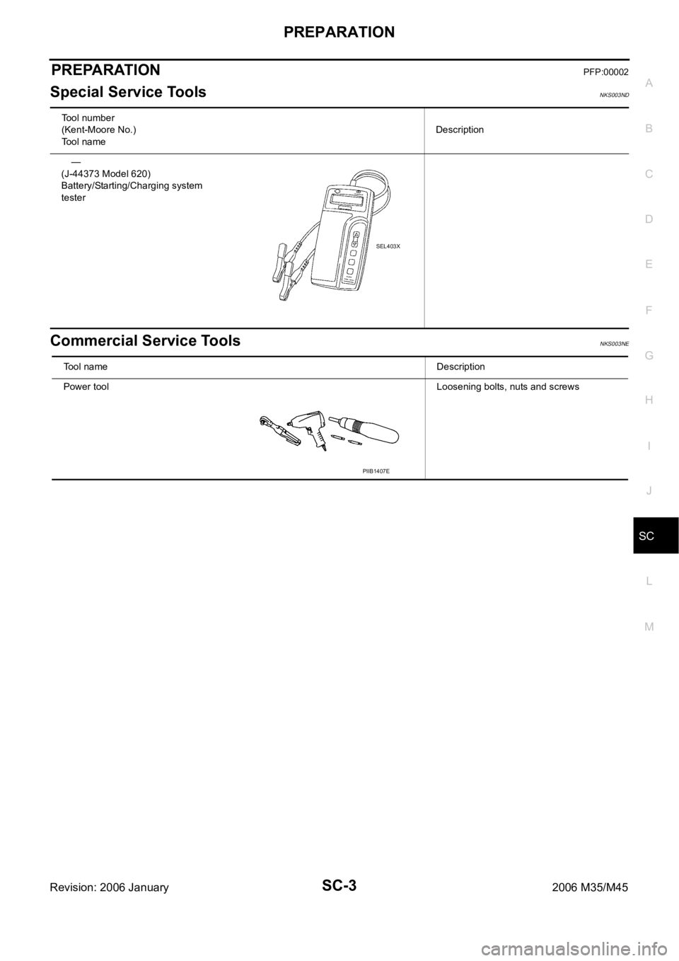
Tool number
(Kent-Moore No.)
Tool nameDescription
—
(J-44373 Model 620)
Battery/Starting/Charging system
tester
SEL403X
Tool nameDescription
Power toolLoosening bolts, nuts and screws
PIIB1407E
Page 5144 of 5621

BATTERY
SC-7
C
D
E
F
G
H
I
J
L
MA
B
SC
Revision: 2006 January2006 M35/M45
If, after charging, the specific gravity of any two cells varies more than 0.050, the battery should be
replaced.
Trouble Diagnosis with Battery/Starting/Charging System Tester (Battery)NKS003NG
CAUTION:
When working with batteries, always wear appropriate eye protection.
NOTE:
To ensure a complete and thorough diagnosis, the battery, starter and alternator test segments must be
done as a set from start to finish.
If battery surface charge is detected while testing, the tester will prompt you to turn on the headlamps to
remove the surface charge.
If necessary, the tester will prompt you to determine if the battery temperature is above or below 0 C (32
F). Choose the appropriate selection by pressing the up or down arrow button, then press “ENTER” to
make the selection.
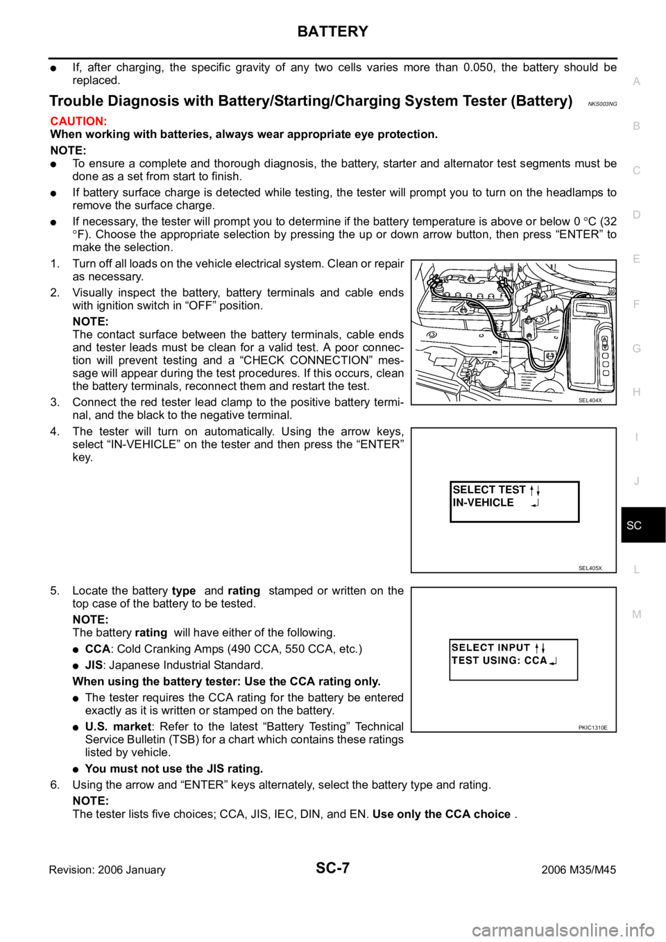
1. Turn off all loads on the vehicle electrical system. Clean or repair
as necessary.
2. Visually inspect the battery, battery terminals and cable ends
with ignition switch in “OFF” position.
NOTE:
The contact surface between the battery terminals, cable ends
and tester leads must be clean for a valid test. A poor connec-
tion will prevent testing and a “CHECK CONNECTION” mes-
sage will appear during the test procedures. If this occurs, clean
the battery terminals, reconnect them and restart the test.
3. Connect the red tester lead clamp to the positive battery termi-
nal, and the black to the negative terminal.
4. The tester will turn on automatically. Using the arrow keys,
select “IN-VEHICLE” on the tester and then press the “ENTER”
key.
5. Locate the battery type and rating stamped or written on the
top case of the battery to be tested.
NOTE:
The battery rating will have either of the following.
CCA: Cold Cranking Amps (490 CCA, 550 CCA, etc.)
JIS: Japanese Industrial Standard.
When using the battery tester: Use the CCA rating only.
The tester requires the CCA rating for the battery be entered
exactly as it is written or stamped on the battery.
U.S. market: Refer to the latest “Battery Testing” Technical
Service Bulletin (TSB) for a chart which contains these ratings
listed by vehicle.
You must not use the JIS rating.
6. Using the arrow and “ENTER” keys alternately, select the battery type and rating.
NOTE:
The tester lists five choices; CCA, JIS, IEC, DIN, and EN. Use only the CCA choice .
SEL404X
SEL405X
PKIC1310E