2006 INFINITI M35 starting
[x] Cancel search: startingPage 3467 of 5621
GI-4
PRECAUTIONS
Revision: 2006 January2006 M35/M45
Precautions Necessary for Steering Wheel Rotation After Battery DisconnectNAS0008J
NOTE:
This Procedure is applied only to models with Intelligent Key system and NVIS/IVIS (NISSAN/INFINITI
VEHICLE IMMOBILIZER SYSTEM - NATS).
Remove and install all control units after disconnecting both battery cables with the ignition knob in the
LOCK position.
Always use CONSULT-II to perform self-diagnosis as a part of each function inspection after finishing
work. If DTC is detected, perform trouble diagnosis according to self-diagnostic results.
For models equipped with the Intelligent Key system and NVIS/IVIS, an electrically controlled steering lock
mechanism is adopted on the key cylinder.
For this reason, if the battery is disconnected or if the battery is discharged, the steering wheel will lock and
steering wheel rotation will become impossible.
If steering wheel rotation is required when battery power is interrupted, follow the procedure below before
starting the repair operation.
OPERATION PROCEDURE
1. Connect both battery cables.
NOTE:
Supply power using jumper cables if battery is discharged.
2. Use the Intelligent Key or mechanical key to turn the ignition switch to the
ACC position. At this time, the
steering lock will be released.
3. Disconnect both battery cables. The steering lock will remain released and the steering wheel can be
rotated.
4. Perform the necessary repair operation.
5. When the repair work is completed, return the ignition switch to the
LOCK position before connecting
the battery cables. (At this time, the steering lock mechanism will engage.)
6. Perform a self-diagnosis check of all control units using CONSULT-II.
Precautions for Procedures without Cowl Top CoverNAS00077
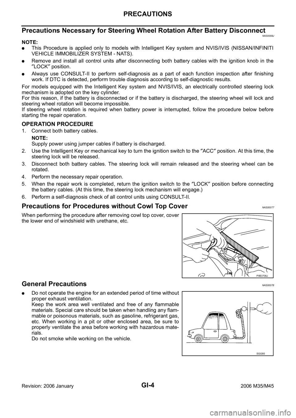
When performing the procedure after removing cowl top cover, cover
the lower end of windshield with urethane, etc.
General PrecautionsNAS00078
Do not operate the engine for an extended period of time without
proper exhaust ventilation.
Keep the work area well ventilated and free of any flammable
materials. Special care should be taken when handling any flam-
mable or poisonous materials, such as gasoline, refrigerant gas,
etc. When working in a pit or other enclosed area, be sure to
properly ventilate the area before working with hazardous mate-
rials.
Do not smoke while working on the vehicle.
PIIB3706J
SGI285
Page 3468 of 5621
PRECAUTIONS
GI-5
C
D
E
F
G
H
I
J
K
L
MB
GI
Revision: 2006 January2006 M35/M45
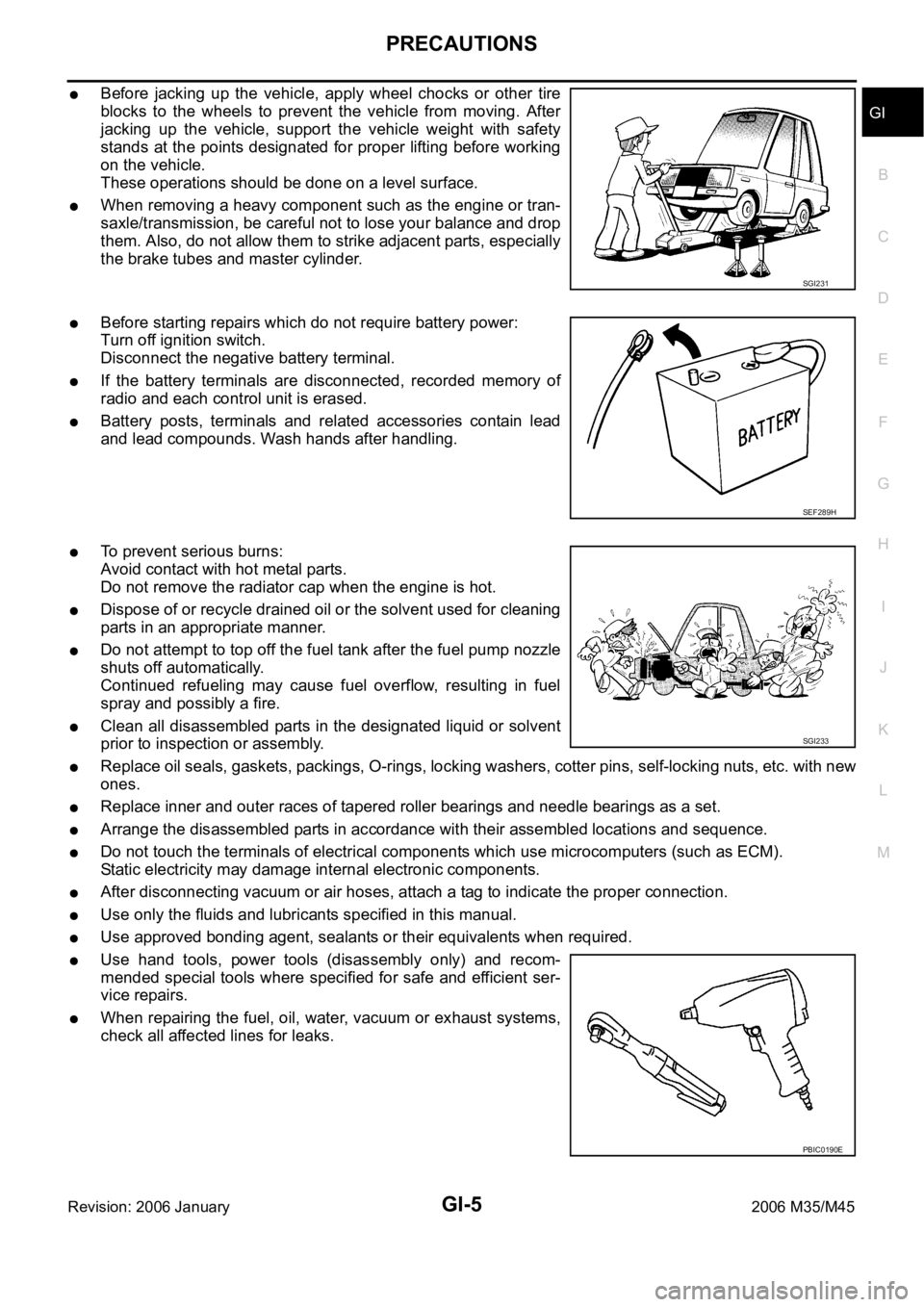
Before jacking up the vehicle, apply wheel chocks or other tire
blocks to the wheels to prevent the vehicle from moving. After
jacking up the vehicle, support the vehicle weight with safety
stands at the points designated for proper lifting before working
on the vehicle.
These operations should be done on a level surface.
When removing a heavy component such as the engine or tran-
saxle/transmission, be careful not to lose your balance and drop
them. Also, do not allow them to strike adjacent parts, especially
the brake tubes and master cylinder.
Before starting repairs which do not require battery power:
Turn off ignition switch.
Disconnect the negative battery terminal.
If the battery terminals are disconnected, recorded memory of
radio and each control unit is erased.
Battery posts, terminals and related accessories contain lead
and lead compounds. Wash hands after handling.
To prevent serious burns:
Avoid contact with hot metal parts.
Do not remove the radiator cap when the engine is hot.
Dispose of or recycle drained oil or the solvent used for cleaning
parts in an appropriate manner.
Do not attempt to top off the fuel tank after the fuel pump nozzle
shuts off automatically.
Continued refueling may cause fuel overflow, resulting in fuel
spray and possibly a fire.
Clean all disassembled parts in the designated liquid or solvent
prior to inspection or assembly.
Replace oil seals, gaskets, packings, O-rings, locking washers, cotter pins, self-locking nuts, etc. with new
ones.
Replace inner and outer races of tapered roller bearings and needle bearings as a set.
Arrange the disassembled parts in accordance with their assembled locations and sequence.
Do not touch the terminals of electrical components which use microcomputers (such as ECM).
Static electricity may damage internal electronic components.
After disconnecting vacuum or air hoses, attach a tag to indicate the proper connection.
Use only the fluids and lubricants specified in this manual.
Use approved bonding agent, sealants or their equivalents when required.
Use hand tools, power tools (disassembly only) and recom-
mended special tools where specified for safe and efficient ser-
vice repairs.
When repairing the fuel, oil, water, vacuum or exhaust systems,
check all affected lines for leaks.
SGI231
SEF289H
SGI233
PBIC0190E
Page 3643 of 5621
IDX-2
ALPHABETICAL INDEX
A
A/C air flow ...................................................... ATC-37
A/C component layout ..................................... ATC-25
A/C compressor mounting ........... ATC-155, ATC-158,
ATC-159
, ATC-160, ATC-162, ATC-164, ATC-165,
ATC-167
, ATC-168, ATC-169
A/C compressor precaution ............................. ATC-12
A/C compressor special service tool ................ ATC-16
A/C control operation (auto A/C) ...................... ATC-33
A/C diagnostic work flow (auto A/C) .............. ATC-111
A/C evaporator ............................................... ATC-168
A/C HFC134a (R134a) system precaution ........ ATC-6
A/C HFC134a (R134a) system service procedure .......
ATC-151
A/C HFC134a (R134a) system service tools ... ATC-17
A/C HFC134a system service equipment precaution ...
ATC-13
A/C lubricant (R134a) ...................................... ATC-26
A/C lubrication oil ........................................... ATC-174
A/C operational check ...................................... ATC-64
A/C self-diagnoses (auto A/C) ........ ATC-55, ATC-111
A/C service data specification ........................ ATC-174
A/C system description (auto A/C) ................... ATC-29
A/C trouble diagnoses (auto A/C) .................... ATC-40
A/C, A - Wiring diagram ................................... ATC-46
A/T fluid checking ...................... AT-13, AT-53, MA-29
A/T fluid cooler cleaning .................................... AT-14
A/T fluid replacement ............................. AT-12, MA-31
A/T fluid temperature sensor ........................... AT-135
A/T IND - Wiring diagram .................................... DI-57
A/T self-diagnoses ............................... AT-92, AT-103
A/T shift lock system ........................................ AT-229
A/T shift lock system - Wiring diagram ............ AT-230
A/T trouble diagnoses ........................................ AT-44
Accelerator control system ............................... ACC-3
Accelerator pedal position (APP) sensor ........ EC-626,
EC-633
, EC-647, EC-1358, EC-1365, EC-1379
Accelerator pedal released position learning .... EC-95,
EC-806
AF1B1-Wiring diagram ...... EC-249, EC-258, EC-267,
EC-277
, EC-657, EC-972, EC-981, EC-990, EC-1000,
EC-1389
AF1B2-Wiring diagram ...... EC-251, EC-260, EC-269,
EC-279
, EC-659, EC-974, EC-983, EC-992, EC-1002,
EC-1391
AF1HB1-Wiring diagram .................... EC-183, EC-905
AF1HB2-Wiring diagram .................... EC-185, EC-907
Air bag .............................................................. SRS-3
Air bag precautions ........................................... SRS-3
Air cleaner and air duct(VK45DE) ................... EM-177
Air cleaner and air duct(VQ35DE) .................... EM-17
Air cleaner filter replacement ............................ MA-25
Air cleaner filter replacement(VQ35DE) ........... MA-18
Air cleaner filter(VQ35DE) ................................ EM-18
Air conditioner cut control .................... EC-35, EC-745
Air flow meter - See Mass air flow sensor ...... EC-205,
EC-214
, EC-927, EC-936
Air fuel ratio sensor 1 ......... EC-246, EC-256, EC-265, EC-274
, EC-655, EC-969, EC-979, EC-988, EC-997,
EC-1387
Air fuel ratio sensor 1 heater ............. EC-182, EC-904
Air mix. door motor ......................... ATC-83, ATC-141
Alternator ........................................................... SC-23
Ambient sensor ............................. ATC-113, ATC-126
Angular tightening application ............................. EM-6
Angular tightening application(VK45DE) ........ EM-164
APPS1 - Wiring diagram ................. EC-628, EC-1360
APPS2 - Wiring diagram ................. EC-635, EC-1367
APPS3 - Wiring diagram ................. EC-649, EC-1381
ASC/BS - Wiring diagram ............... EC-587, EC-1313
ASC/SW - Wiring diagram .............. EC-570, EC-1296
ASCBOF - Wiring diagram .............. EC-708, EC-1450
ASCD .................................................. EC-36, EC-746
ASCD (automatic speed control device) ........... ACS-3
ASCIND - Wiring diagram ............... EC-715, EC-1457
AT indicator lamp ................................................ DI-56
Auto air conditioner - Wiring diagram ............. ATC-46
Auto amp ...................................................... ATC-125
Auto anti-dazzling inside mirror .......... GW-71, GW-72
Automatic amplifier ........... ATC-53, ATC-66, ATC-125
Automatic transmission fluid replacement ........ MA-32
AWD - Wiring diagram ....................................... TF-17
Axle ................................................................... MA-37
B
Back-up lamp ................................................... LT-246
Basic inspection .................................. EC-77, EC-788
Battery ................................................................. SC-4
Battery current sensor ....... EC-537, EC-543, EC-549,
EC-555
, EC-1263, EC-1269, EC-1275, EC-1281
Battery/Starting/Charging System Tester .......... SC-28
Battery/Starting/Charging System Tester(Battery) SC-7
Battery/Starting/Charging System Tester(Starting
system) .............................................................. SC-13
BCM (Body control module) .............................. BCS-3
Block heater(VK45DE) .................................... EM-249
Block heater(VQ35DE) ................................... EM-123
Blower motor ................................... ATC-89, ATC-132
Blower unit .................................................... ATC-130
Brake fluid level ................................................ MA-35
Brake hydraulic line ........................................... BR-12
Brake inspection ............................................... MA-36
Brake lines and cables inspection .................... MA-35
Brake pedal .......................................................... BR-6
Brake switch ................................... EC-598, EC-1329
BRK/SW - Wiring diagram .............. EC-600, EC-1331
Bulb specifications ........................................... LT-315
Bumper, front ...................................................... EI-11
Bumper, rear ....................................................... EI-14
C
Camshaft inspection(VK45DE) ....................... EM-216
Camshaft inspection(VQ35DE) ......................... EM-86
Camshaft position sensor (PHASE) EC-383, EC-1106
Camshaft(VK45DE) ........................................ EM-215
Page 3648 of 5621
IDX-7
A
C
D
E
F
G
H
I
J
K
L B
IDX
ALPHABETICAL INDEX
LT-266
Rear disc brake ................................................. BR-29
Rear door ............................................ BL-190, GW-67
Rear parcel shelf finisher ..................................... EI-42
Rear seat ......................................................... SE-172
Rear seat belt .................................................... SB-32
Rear suspension ............................................... RSU-5
Rear window ..................................................... GW-61
Rear window defogger ...................................... GW-73
Refrigerant connection precaution ..................... ATC-7
Refrigerant discharging evacuating charging ATC-151
Refrigerant general precaution .......................... ATC-7
Refrigerant lines ............................................ ATC-151
Refrigerant pressure sensor ........... EC-692, EC-1434,
ATC-98
, ATC-167
Refrigeration cycle ........................................... ATC-20
Removal and installation (A/T) ........... AT-271, AT-275
Removal and installation (Transfer) .................... TF-44
Reverse interlock door mirror ........................... GW-96
Revolution sensor (A/T) ...................... AT-119, AT-261
Rocker cover(VK45DE) ................................... EM-199
Rocker cover(VQ35DE) ..................................... EM-51
Room lamp - See Interior lamp ......................... LT-267
ROOM/L - Wiring diagram ................................ LT-274
RP/SEN - Wiring diagram ................ EC-693, EC-1435
S
SAE J1979 - Service $01 - 09 ............. EC-54
, EC-764
SEAT - Wiring diagram ...................................... SE-98
Seat belt inspection ........................................... SB-33
Seat belt, front ................................................... SB-30
Seat belt, rear .................................................... SB-32
Seat, rear ......................................................... SE-172
Self-diagnosis (Transfer) .................................... TF-22
SEN/PW - Wiring diagram ............... EC-500, EC-1219
SHIFT - Wiring diagram ................................... AT-230
Shift lock system .............................................. AT-229
Shock absorber (rear) ..................................... RSU-10
Side air bag (satellite) sensor .......................... SRS-46
Side curtain air bag .......................................... SRS-43
Side trim .............................................................. EI-37
SMJ (super multiple junction) .......................... PG-106
Spark plug replacement ..................................... MA-27
Spark plug replacement(VQ35DE) .................... MA-20
Spark plug(VK45DE) ....................................... EM-191
Spark plug(VQ35DE) ......................................... EM-43
Specification value ............................. EC-155, EC-868
Speedometer ........................................................ DI-5
Spiral cable ...................................................... SRS-40
SROOF - Wiring diagram .................................. RF-13
SRS - See Supplemental Restraint System ...... SRS-5
SRS - Wiring diagram ...................................... SRS-12
SRS Trouble diagnoses ..................................... SRS-8
Stabilizer bar (rear) ......................................... RSU-17
Stall test (A/T) .................................................... AT-53
Standardized relay ........................................... PG-109
START - Wiring diagram ................................... SC-11
Starter ................................................................ SC-10
Starting system .................................................. SC-10
Steering gear and linkage inspection ................ MA-36
Steering linkage ................................................. PS-18
Steering wheel and column ................... PS-10, PS-13
Steering wheel turning force .............................. PS-10
Stop lamp .......................................................... LT-243
Stop lamp switch .............................. EC-598, EC-1329
STSIG - Wiring diagram ................................... AT-109
Sun roof, electric ................................................ RF-10
Sunload sensor ............................. ATC-119, ATC-128
Sunroof .................................................. RF-25, RF-28
Sunshade ............................................................ EI-44
Supplemental Restraint System ....................... SRS-5
Supplemental restraint system - Wiring diagram ..........
SRS-12
Suspension ....................................................... MA-37
Symbols and abbreviations ...................... GI-11, GI-24
System readiness test (SRT) code ...... EC-60, EC-770
T
Tachometer ........................................................... DI-5
Tail lamp ........................................................... LT-249
TCM circuit diagram ........................................... AT-52
TCM inspection table ......................................... AT-89
Thermostat(VK45DE) ....................................... CO-55
Thermostat(VQ35DE) ....................................... CO-29
Three way catalyst function (Bank 1) EC-392, EC-1113
Three way catalyst function (Bank 2) EC-392, EC-1113
Three way catalyst precautions ............................ GI-6
Three way catalyst(VK45DE) .......................... EM-183
Throttle control motor ....................... EC-619, EC-1351
Throttle control motor relay .............. EC-607, EC-1338
Throttle position sensor (TPS) .......... EC-231, EC-354,
EC-533
, EC-535, EC-640, EC-954, EC-1077, EC-1259,
EC-1261
, EC-1372
Throttle valve closed position learning . EC-95, EC-806
Tie-rod ............................................................... PS-18
Timing chain(VK45DE) ................................... EM-203
Timing chain(VQ35DE) ..................................... EM-64
Tire rotation ....................................................... MA-35
TLID - Wiring diagram ...................................... BL-211
Top tether strap child restraint ........................... SB-37
Torque converter installation ............. AT-274, AT-277
Torque convertor clutch solenoid valve AT-126, AT-128
TPS1 - Wiring diagram .................... EC-356, EC-1079
TPS2 - Wiring diagram ...................... EC-233, EC-956
TPS3 - Wiring diagram .................... EC-642, EC-1374
Transfer control unit inspection table ................. TF-20
TRNSCV - Wiring diagram ............................... BL-281
Trouble diagnoses .............................................. GI-12
Trunk lid ........................................................... BL-203
Trunk lid opener - See Trunk lid ...................... BL-209
TURN - Wiring diagram .................................... LT-215
Turn signal lamp ............................................... LT-211
Two trip detection logic ........................ EC-54, EC-764
Tyre pressure monitoring system - trouble diagnoses ..
WT-13
Page 4750 of 5621
![INFINITI M35 2006 Factory Service Manual ENGINE OIL
LU-7
[VQ35DE]
C
D
E
F
G
H
I
J
K
L
MA
LU
Revision: 2006 January2006 M35/M45
ENGINE OILPFP:KLA92
InspectionNBS004PW
ENGINE OIL LEVEL
NOTE:
Before starting engine, put vehicle horizontally and INFINITI M35 2006 Factory Service Manual ENGINE OIL
LU-7
[VQ35DE]
C
D
E
F
G
H
I
J
K
L
MA
LU
Revision: 2006 January2006 M35/M45
ENGINE OILPFP:KLA92
InspectionNBS004PW
ENGINE OIL LEVEL
NOTE:
Before starting engine, put vehicle horizontally and](/manual-img/42/57023/w960_57023-4749.png)
ENGINE OIL
LU-7
[VQ35DE]
C
D
E
F
G
H
I
J
K
L
MA
LU
Revision: 2006 January2006 M35/M45
ENGINE OILPFP:KLA92
InspectionNBS004PW
ENGINE OIL LEVEL
NOTE:
Before starting engine, put vehicle horizontally and check the engine oil level. If engine is already started, stop
it and allow 10 minutes before checking.
1. Pull out oil level gauge and wipe it clean.
2. Insert oil level gauge and make sure the engine oil level is within
the range shown in the figure.
3. If it is out of range, adjust it.
NOTE:
When checking the engine oil level, insert oil level gauge with its
tip aligned with oil level gauge guide on cylinder head. (In figure,
air cleaner case and air duct are removed.)
ENGINE OIL APPEARANCE
Check engine oil for white turbidity or heavy contamination.
If engine oil becomes turbid and white, it is highly probable that it is contaminated with engine coolant.
Repair or replace damaged parts.
ENGINE OIL LEAKAGE
Check for engine oil leakage around the following areas:
Oil pans (lower and upper)
Oil pan drain plug
Oil pressure switch
Oil filter
Oil filter bracket (AWD models)
Oil cooler
Water pump cover
Chain tensioner cover
Intake valve timing control cover and intake valve timing control solenoid valve
Mating surface between cylinder head and rocker cover
Mating surface between front timing chain case and rear timing chain case
Mating surface between rear timing chain case and cylinder head
Mating surface between rear timing chain case and cylinder block
Mating surface between rear timing chain case and oil pan (upper)
Mating surface between cylinder block and cylinder head
PBIC0249E
KBIA1343E
Page 4769 of 5621
![INFINITI M35 2006 Factory Service Manual LU-26
[VK45DE]
ENGINE OIL
Revision: 2006 January2006 M35/M45
ENGINE OILPFP:KLA92
InspectionNBS004QC
ENGINE OIL LEVEL
NOTE:
Before starting engine, put vehicle horizontally and check the engine oil lev INFINITI M35 2006 Factory Service Manual LU-26
[VK45DE]
ENGINE OIL
Revision: 2006 January2006 M35/M45
ENGINE OILPFP:KLA92
InspectionNBS004QC
ENGINE OIL LEVEL
NOTE:
Before starting engine, put vehicle horizontally and check the engine oil lev](/manual-img/42/57023/w960_57023-4768.png)
LU-26
[VK45DE]
ENGINE OIL
Revision: 2006 January2006 M35/M45
ENGINE OILPFP:KLA92
InspectionNBS004QC
ENGINE OIL LEVEL
NOTE:
Before starting engine, put vehicle horizontally and check the engine oil level. If engine is already started, stop
it and allow 15 minutes before checking.
1. Pull out oil level gauge and wipe it clean.
2. Insert oil level gauge and make sure the engine oil level is within
the range shown in the figure.
3. If it is out of range, adjust it.
ENGINE OIL APPEARANCE
Check engine oil for white turbidity or heavy contamination.
If engine oil becomes turbid and white, it is highly probable that it is contaminated with engine coolant.
Repair or replace damaged parts.
ENGINE OIL LEAKAGE
Check for oil leakage around the following area.
Oil pan
Oil pan drain plug
Oil pressure switch
Oil filter
Intake valve timing control cover
Intake valve timing control solenoid valve
Front cover
Chain tensioner cover
Mating surface between cylinder block and cylinder head
Mating surface between cylinder head and rocker cover
Crankshaft oil seals (front and rear)
OIL PRESSURE CHECK
WAR NING :
Be careful not to burn yourself, as engine oil may be hot.
Oil pressure check should be done in “Parking position”.
1. Check the engine oil level. Refer to LU-26, "
ENGINE OIL LEVEL" .
2. Remove front engine undercover with power tool.
3. Disconnect harness connector at oil pressure switch, and
remove oil pressure switch using deep socket (commercial ser-
vice tool).
CAUTION:
Do not drop or shock oil pressure switch.
PBIC0801E
PBIC1524E
Page 4851 of 5621
PG-24
IPDM E/R (INTELLIGENT POWER DISTRIBUTION MODULE ENGINE ROOM)
Revision: 2006 January2006 M35/M45
Auto Active TestNKS004E7
DESCRIPTION
In auto active test mode, operation inspection can be performed when IPDM E/R sends a drive signal to the
following systems:
Rear window defogger
Front wiper (LO, HI)
Tail lamps, parking lamps and license plate lamps
Front fog lamps
Headlamps (LO, HI)
A/C compressor (magnetic clutch)
Cooling fan
Oil pressure warning lamp
OPERATION PROCEDURE
1. Close hood and front door (passenger side), and then lift wiper arms away from windshield (to prevent
glass damage by wiper operation).
NOTE:
When auto active test is performed with hood opened, sprinkle water on windshield beforehand.
2. Turn ignition switch OFF.
3. Turn ignition switch ON, and within 20 seconds, press driver's door switch 10 times (close other doors).
Then turn ignition switch OFF.
4. Turn ignition switch ON within 10 seconds after ignition switch OFF.
5. When auto active test mode is actuated, horn chirps once. Oil pressure warning lamp starts blinking.
6. After a series of operations is repeated three times, auto active test is completed.
NOTE:
When auto active test mode has to be cancelled halfway, turn ignition switch OFF.
CAUTION:
Never start the engine.
If the engine starting operation is made, delete DTC on the self-diag results of CONSULT-II.
Refer to BL-81, "
CONSULT-II Application Items" .
Be sure to inspect GW-52, "Door Switch Check" when the auto active test cannot be performed.
Page 4860 of 5621
PDU (POWER DISTRIBUTION UNIT)
PG-33
C
D
E
F
G
H
I
J
L
MA
B
PG
Revision: 2006 January2006 M35/M45
PDU (POWER DISTRIBUTION UNIT)PFP:285F1
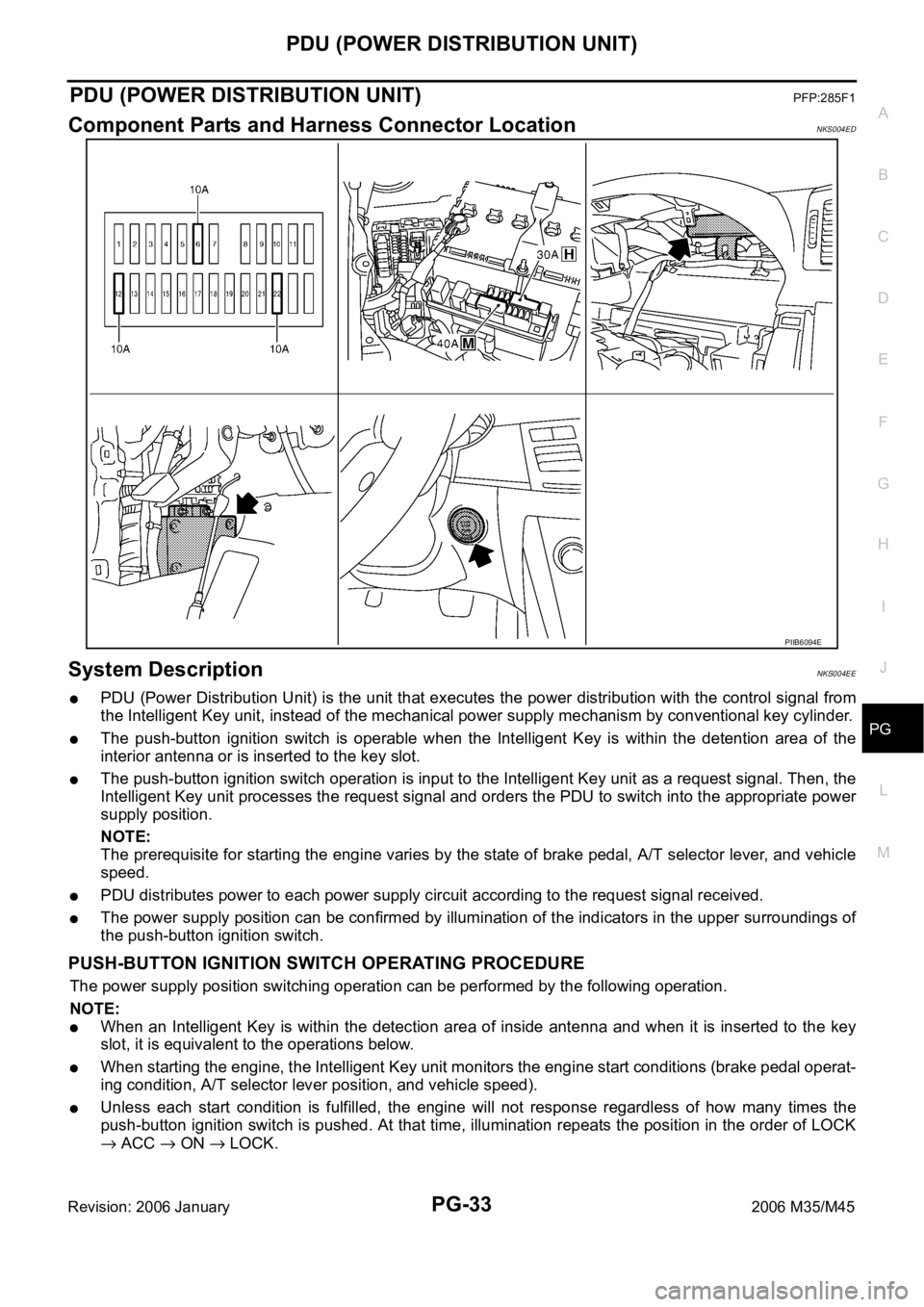
Component Parts and Harness Connector LocationNKS004ED
System DescriptionNKS004EE
PDU (Power Distribution Unit) is the unit that executes the power distribution with the control signal from
the Intelligent Key unit, instead of the mechanical power supply mechanism by conventional key cylinder.
The push-button ignition switch is operable when the Intelligent Key is within the detention area of the
interior antenna or is inserted to the key slot.
The push-button ignition switch operation is input to the Intelligent Key unit as a request signal. Then, the
Intelligent Key unit processes the request signal and orders the PDU to switch into the appropriate power
supply position.
NOTE:
The prerequisite for starting the engine varies by the state of brake pedal, A/T selector lever, and vehicle
speed.
PDU distributes power to each power supply circuit according to the request signal received.
The power supply position can be confirmed by illumination of the indicators in the upper surroundings of
the push-button ignition switch.
PUSH-BUTTON IGNITION SWITCH OPERATING PROCEDURE
The power supply position switching operation can be performed by the following operation.
NOTE:
When an Intelligent Key is within the detection area of inside antenna and when it is inserted to the key
slot, it is equivalent to the operations below.
When starting the engine, the Intelligent Key unit monitors the engine start conditions (brake pedal operat-
ing condition, A/T selector lever position, and vehicle speed).
Unless each start condition is fulfilled, the engine will not response regardless of how many times the
push-button ignition switch is pushed. At that time, illumination repeats the position in the order of LOCK
ACC ON LOCK.
PIIB6094E