2006 INFINITI M35 engine
[x] Cancel search: enginePage 5083 of 5621

RSU-2
PRECAUTIONS
Revision: 2006 January2006 M35/M45
PRECAUTIONSPFP:00001
PrecautionsNES000J2
When installing rubber bushings, final tightening must be carried out under unladen conditions with tires
on ground. Oil will shorten the life of rubber bushings. Be sure to wipe off any spilled oil.
–Unladen conditions mean that fuel, engine coolant and lubricant are full. Spare tire, jack, hand tools and
mats are in designated positions.
After servicing suspension parts, be sure to check wheel alignment.
Self-lock nuts are not reusable. Always use new ones when installing. Since new self-lock nuts are pre-
oiled, tighten as they are.
Page 5086 of 5621
REAR SUSPENSION ASSEMBLY
RSU-5
C
D
F
G
H
I
J
K
L
MA
B
RSU
Revision: 2006 January2006 M35/M45
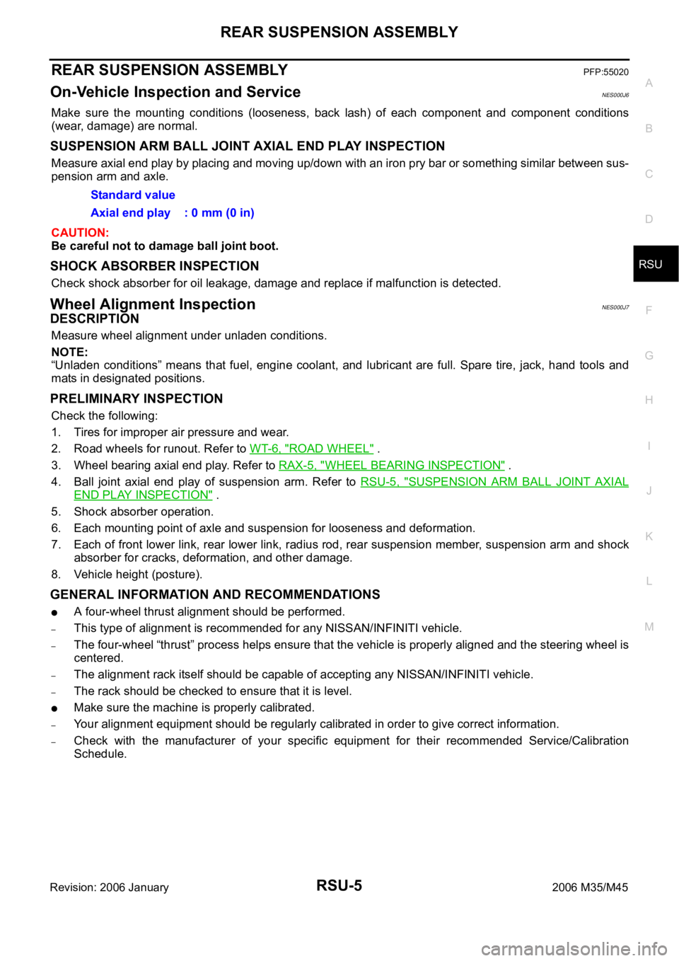
REAR SUSPENSION ASSEMBLYPFP:55020
On-Vehicle Inspection and ServiceNES000J6
Make sure the mounting conditions (looseness, back lash) of each component and component conditions
(wear, damage) are normal.
SUSPENSION ARM BALL JOINT AXIAL END PLAY INSPECTION
Measure axial end play by placing and moving up/down with an iron pry bar or something similar between sus-
pension arm and axle.
CAUTION:
Be careful not to damage ball joint boot.
SHOCK ABSORBER INSPECTION
Check shock absorber for oil leakage, damage and replace if malfunction is detected.
Wheel Alignment InspectionNES000J7
DESCRIPTION
Measure wheel alignment under unladen conditions.
NOTE:
“Unladen conditions” means that fuel, engine coolant, and lubricant are full. Spare tire, jack, hand tools and
mats in designated positions.
PRELIMINARY INSPECTION
Check the following:
1. Tires for improper air pressure and wear.
2. Road wheels for runout. Refer to WT-6, "
ROAD WHEEL" .
3. Wheel bearing axial end play. Refer to RAX-5, "
WHEEL BEARING INSPECTION" .
4. Ball joint axial end play of suspension arm. Refer to RSU-5, "
SUSPENSION ARM BALL JOINT AXIAL
END PLAY INSPECTION" .
5. Shock absorber operation.
6. Each mounting point of axle and suspension for looseness and deformation.
7. Each of front lower link, rear lower link, radius rod, rear suspension member, suspension arm and shock
absorber for cracks, deformation, and other damage.
8. Vehicle height (posture).
GENERAL INFORMATION AND RECOMMENDATIONS
A four-wheel thrust alignment should be performed.
–This type of alignment is recommended for any NISSAN/INFINITI vehicle.
–The four-wheel “thrust” process helps ensure that the vehicle is properly aligned and the steering wheel is
centered.
–The alignment rack itself should be capable of accepting any NISSAN/INFINITI vehicle.
–The rack should be checked to ensure that it is level.
Make sure the machine is properly calibrated.
–Your alignment equipment should be regularly calibrated in order to give correct information.
–Check with the manufacturer of your specific equipment for their recommended Service/Calibration
Schedule.Standard value
Axial end play : 0 mm (0 in)
Page 5099 of 5621
RSU-18
SERVICE DATA
Revision: 2006 January2006 M35/M45
SERVICE DATAPFP:00030
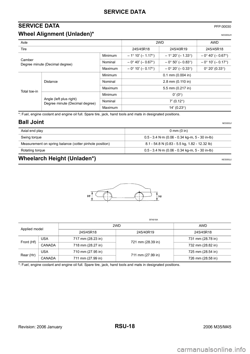
Wheel Alignment (Unladen)*NES000JH
*: Fuel, engine coolant and engine oil full. Spare tire, jack, hand tools and mats in designated positions.
Ball JointNES000JI
Wheelarch Height (Unladen*)NES000JJ
*: Fuel, engine coolant and engine oil full. Spare tire, jack, hand tools and mats in designated positions. Axle2WD AWD
Tire 245/45R18 245/40R19 245/45R18
Camber
Degree minute (Decimal degree)Minimum – 1
10 (– 1.17)– 1 20 (– 1.33)– 0 40 (– 0.67)
Nominal – 0
40 (– 0.67)– 0 50 (– 0.83)– 0 10 (– 0.17)
Maximum – 0
10 (– 0.17)– 0 20 (– 0.33)0 20 (0.33)
Total toe-inDistanceMinimum 0.1 mm (0.004 in)
Nominal 2.8 mm (0.110 in)
Maximum 5.5 mm (0.217 in)
Angle (left plus right)
Degree minute (Decimal degree)Minimum 0
(0)
Nominal 7
(0.12)
Maximum 14
(0.23)
Axial end play0 mm (0 in)
Swing torque 0.5 - 3.4 Nꞏm (0.06 - 0.34 kg-m, 5 - 30 in-lb)
Measurement on spring balance (cotter pinhole position) 8.1 - 54.8 N (0.83 - 5.5 kg, 1.82 - 12.32 lb)
Rotating torque 0.5 - 3.4 Nꞏm (0.06 - 0.34 kg-m, 5 - 30 in-lb)
Applied model2WD AWD
245/45R18 245/40R19 245/45R18
Front (Hf)USA 717 mm (28.23 in)
721 mm (28.39 in)731 mm (28.78 in)
CANADA 718 mm (28.27 in) 732 mm (28.82 in)
Rear (Hr)USA 710 mm (27.95 in)
711 mm (27.99 in)725 mm (28.54 in)
CANADA 711 mm (27.99 in) 726 mm (28.58 in)
SFA818A
Page 5127 of 5621
SB-28
PRE-CRASH SEAT BELT
Revision: 2006 January2006 M35/M45
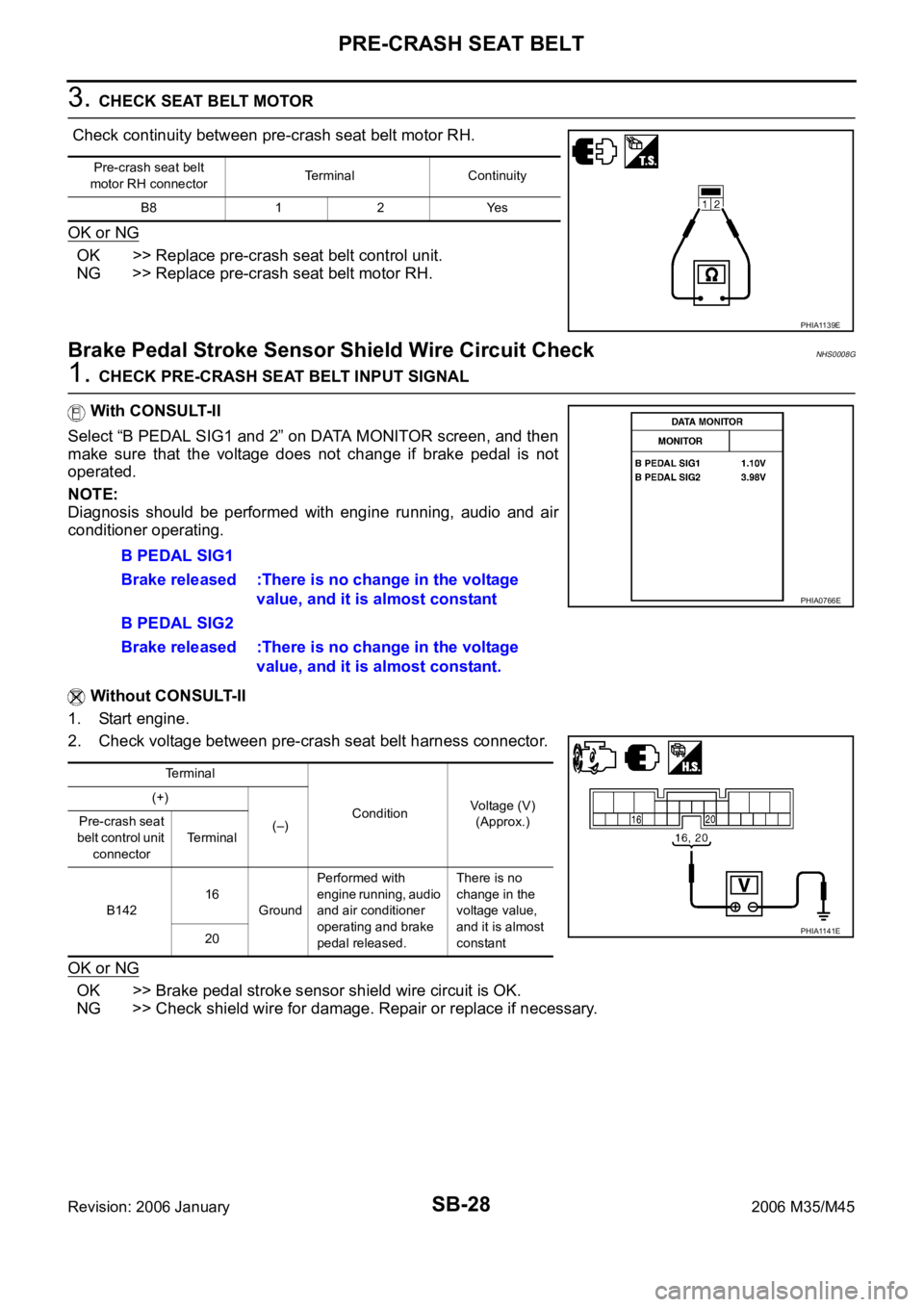
3. CHECK SEAT BELT MOTOR
Check continuity between pre-crash seat belt motor RH.
OK or NG
OK >> Replace pre-crash seat belt control unit.
NG >> Replace pre-crash seat belt motor RH.
Brake Pedal Stroke Sensor Shield Wire Circuit CheckNHS0008G
1. CHECK PRE-CRASH SEAT BELT INPUT SIGNAL
With CONSULT-II
Select “B PEDAL SIG1 and 2” on DATA MONITOR screen, and then
make sure that the voltage does not change if brake pedal is not
operated.
NOTE:
Diagnosis should be performed with engine running, audio and air
conditioner operating.
Without CONSULT-II
1. Start engine.
2. Check voltage between pre-crash seat belt harness connector.
OK or NG
OK >> Brake pedal stroke sensor shield wire circuit is OK.
NG >> Check shield wire for damage. Repair or replace if necessary.
Pre-crash seat belt
motor RH connectorTerminal Continuity
B8 1 2 Yes
PHIA1139E
B PEDAL SIG1
Brake released :There is no change in the voltage
value, and it is almost constant
B PEDAL SIG2
Brake released :There is no change in the voltage
value, and it is almost constant.
Terminal
ConditionVoltage (V)
(Approx.) (+)
(–) Pre-crash seat
belt control unit
connectorTerminal
B14216
GroundPerformed with
engine running, audio
and air conditioner
operating and brake
pedal released.There is no
change in the
voltage value,
and it is almost
constant 20
PHIA0766E
PHIA1141E
Page 5138 of 5621
SC-1
STARTING & CHARGING SYSTEM
K ELECTRICAL
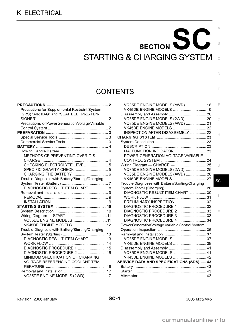
CONTENTS
C
D
E
F
G
H
I
J
L
M
SECTION SC
A
B
SC
Revision: 2006 January2006 M35/M45
STARTING & CHARGING SYSTEM
PRECAUTIONS .......................................................... 2
Precautions for Supplemental Restraint System
(SRS) “AIR BAG” and “SEAT BELT PRE-TEN-
SIONER” .................................................................. 2
Precautions for Power Generation Voltage Variable
Control System ......................................................... 2
PREPARATION ........................................................... 3
Special Service Tools ............................................... 3
Commercial Service Tools ........................................ 3
BATTERY .................................................................... 4
How to Handle Battery ............................................. 4
METHODS OF PREVENTING OVER-DIS-
CHARGE ............................................................... 4
CHECKING ELECTROLYTE LEVEL .................... 5
SPECIFIC GRAVITY CHECK ............................... 5
CHARGING THE BATTERY ................................. 6
Trouble Diagnosis with Battery/Starting/Charging
System Tester (Battery) ............................................ 7
DIAGNOSTIC RESULT ITEM CHART .................. 8
Removal and Installation .......................................... 9
REMOVAL ........................................................
..... 9
INSTALLATION ..................................................... 9
STARTING SYSTEM ................................................ 10
System Description ................................................ 10
Wiring Diagram — START — .................................. 11
VQ35DE ENGINE MODELS ................................ 11
VK45DE ENGINE MODELS ............................... 12
Trouble Diagnosis with Battery/Starting/Charging
System Tester (Starting) ......................................... 13
DIAGNOSTIC RESULT ITEM CHART ................ 13
WORK FLOW ...................................................... 14
DIAGNOSTIC PROCEDURE 1 ........................... 15
DIAGNOSTIC PROCEDURE 2 ........................... 16
MINIMUM SPECIFICATION OF CRANKING
VOLTAGE REFERENCING COOLANT TEM-
PERATURE ......................................................... 16
Removal and Installation ........................................ 17
VQ35DE ENGINE MODELS (2WD) .................... 17VQ35DE ENGINE MODELS (AWD) .................... 18
VK45DE ENGINE MODELS ................................ 19
Disassembly and Assembly .................................... 20
VQ35DE ENGINE MODELS (2WD) .................... 20
VQ35DE ENGINE MODELS (AWD) .................... 21
VK45DE ENGINE MODELS ................................ 22
INSPECTION AFTER DISASSEMBLY ................ 22
CHARGING SYSTEM ............................................... 23
System Description ................................................. 23
DESCRIPTION .................................................... 23
MALFUNCTION INDICATOR .............................. 23
POWER GENERATION VOLTAGE VARIABLE
CONTROL SYSTEM ........................................... 24
Wiring Diagram — CHARGE — ............................. 25
VQ35DE ENGINE MODELS (2WD) .................... 25
VQ35DE ENGINE MODELS (AWD) .................... 26
VK45DE ENGINE MODELS .............................
... 27
Trouble Diagnoses with Battery/Starting/Charging
System Tester (Charging) ....................................... 28
DIAGNOSTIC RESULT ITEM CHART ................ 30
WORK FLOW ...................................................... 31
PRELIMINARY INSPECTION ............................. 32
DIAGNOSTIC PROCEDURE 1 ........................... 32
DIAGNOSTIC PROCEDURE 2 ........................... 33
DIAGNOSTIC PROCEDURE 3 ........................... 33
DIAGNOSTIC PROCEDURE 4 ........................... 34
Power Generation Voltage Variable Control System
Operation Inspection .............................................. 35
Removal and Installation ........................................ 37
VQ35DE ENGINE MODELS ............................... 37
VK45DE ENGINE MODELS ................................ 39
Disassembly and Assembly .................................... 41
VQ35DE ENGINE MODELS ............................... 41
VK45DE ENGINE MODELS ................................ 42
SERVICE DATA AND SPECIFICATIONS (SDS) ...... 43
Battery .................................................................... 43
Starter ..................................................................... 43
Alternator ................................................................ 43
Page 5141 of 5621
SC-4
BATTERY
Revision: 2006 January2006 M35/M45
BATTERY PFP:00011
How to Handle Battery NKS003NF
CAUTION:
If it becomes necessary to start the engine with a booster battery and jumper cables, use a 12-volt
booster battery.
After connecting battery cables, ensure that they are tightly clamped to battery terminals for good
contact.
Never add distilled water through the hole used to check specific gravity.
METHODS OF PREVENTING OVER-DISCHARGE
The following precautions must be taken to prevent over-discharging a battery.
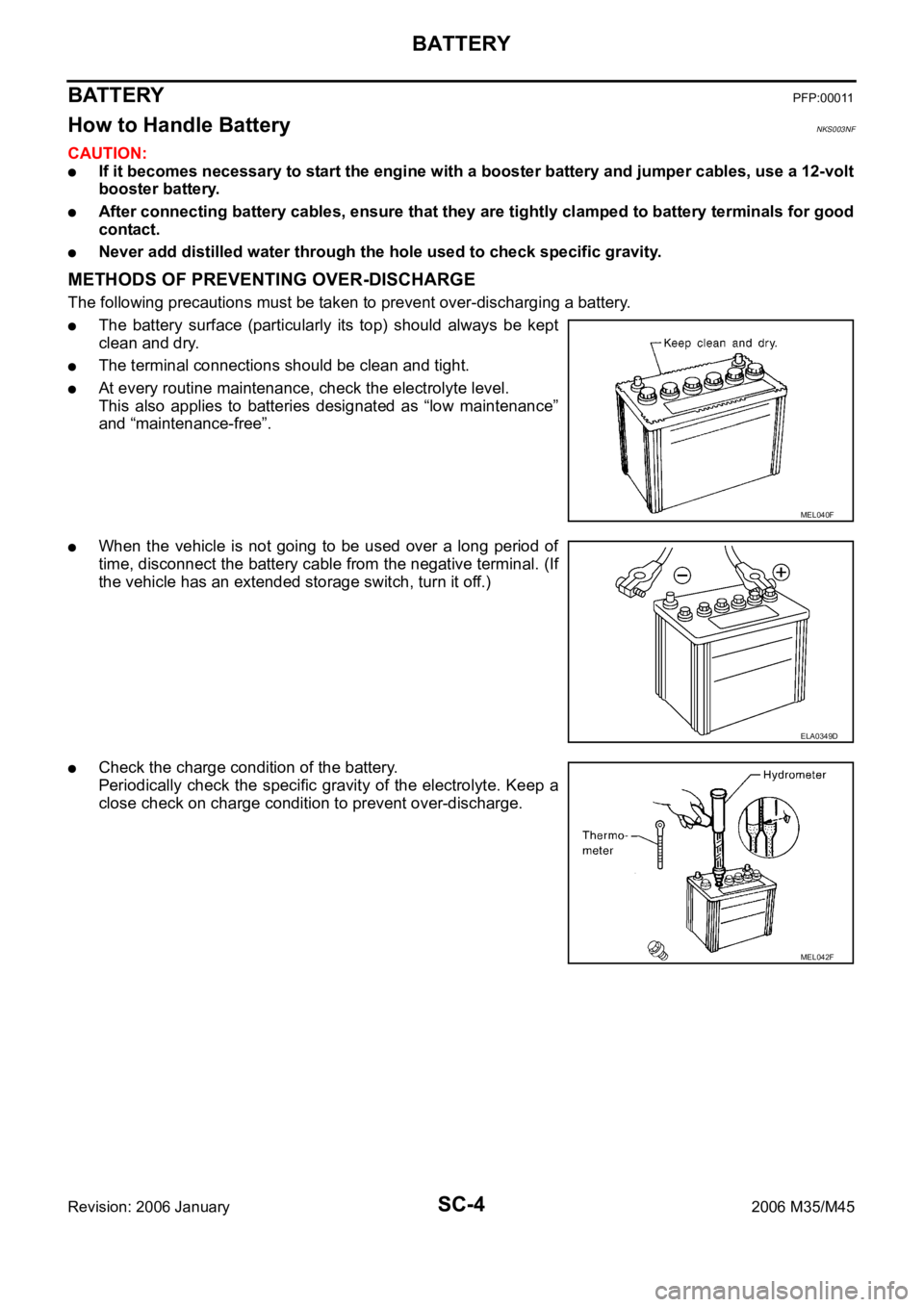
The battery surface (particularly its top) should always be kept
clean and dry.
The terminal connections should be clean and tight.
At every routine maintenance, check the electrolyte level.
This also applies to batteries designated as “low maintenance”
and “maintenance-free”.
When the vehicle is not going to be used over a long period of
time, disconnect the battery cable from the negative terminal. (If
the vehicle has an extended storage switch, turn it off.)
Check the charge condition of the battery.
Periodically check the specific gravity of the electrolyte. Keep a
close check on charge condition to prevent over-discharge.
MEL040F
ELA0349D
MEL042F
Page 5146 of 5621
BATTERY
SC-9
C
D
E
F
G
H
I
J
L
MA
B
SC
Revision: 2006 January2006 M35/M45
Removal and Installation NKS003NH
REMOVAL
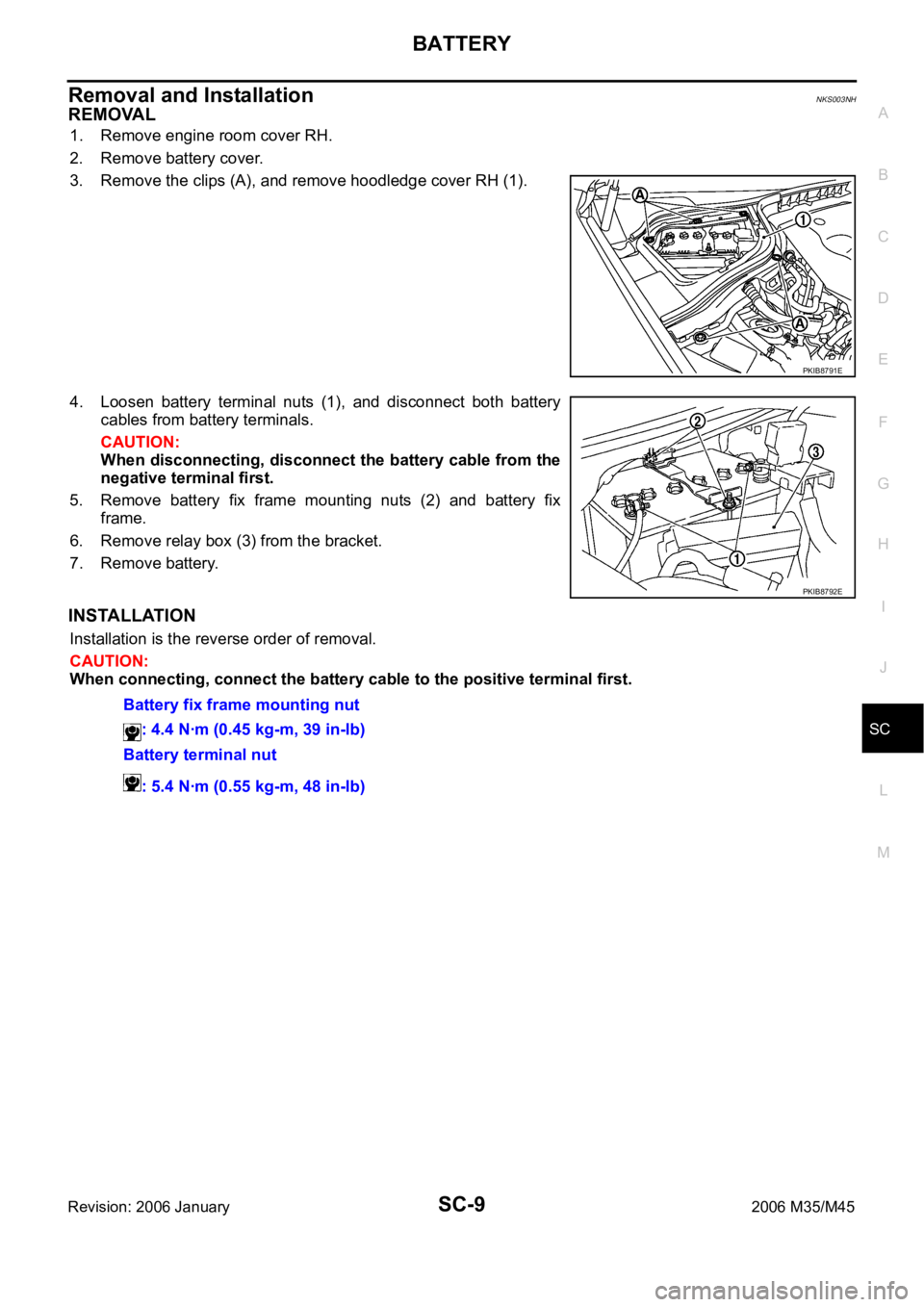
1. Remove engine room cover RH.
2. Remove battery cover.
3. Remove the clips (A), and remove hoodledge cover RH (1).
4. Loosen battery terminal nuts (1), and disconnect both battery
cables from battery terminals.
CAUTION:
When disconnecting, disconnect the battery cable from the
negative terminal first.
5. Remove battery fix frame mounting nuts (2) and battery fix
frame.
6. Remove relay box (3) from the bracket.
7. Remove battery.
INSTALLATION
Installation is the reverse order of removal.
CAUTION:
When connecting, connect the battery cable to the positive terminal first.
PKIB8791E
PKIB8792E
Battery fix frame mounting nut
: 4.4 Nꞏm (0.45 kg-m, 39 in-lb)
Battery terminal nut
: 5.4 Nꞏm (0.55 kg-m, 48 in-lb)
Page 5147 of 5621

SC-10
STARTING SYSTEM
Revision: 2006 January2006 M35/M45
STARTING SYSTEM PFP:00011
System Description NKS003NI
Power is supplied at all times
through 15A fuse (No. 78, located in the IPDM E/R)
to CPU of IPDM E/R,
through 15A fuse (No. 71, located in the IPDM E/R)
to CPU of IPDM E/R.
Ground is supplied
to IPDM E/R terminals 38 and 51
from grounds E22 and E43.
When the selector lever in the P or N position, power is supplied
from TCM, and through A/T assembly terminal 9
to IPDM E/R terminal 53.
And then provided that IPDM E/R receives a starter relay ON signal with CAN communication, starter relay is
energized.
With the ignition switch in the START position, power is supplied
through IPDM E/R terminal 3
to starter motor terminal 1.
The starter motor plunger closes and provides a closed circuit between the battery and starter motor. The
starter motor is grounded to the engine block. With power and ground supplied, cranking occurs and the
engine starts.