2006 INFINITI M35 ECO mode
[x] Cancel search: ECO modePage 1054 of 5621
INTELLIGENT KEY SYSTEM
BL-115
C
D
E
F
G
H
J
K
L
MA
B
BL
Revision: 2006 January2006 M35/M45
Check Park Position SwitchNIS001XX
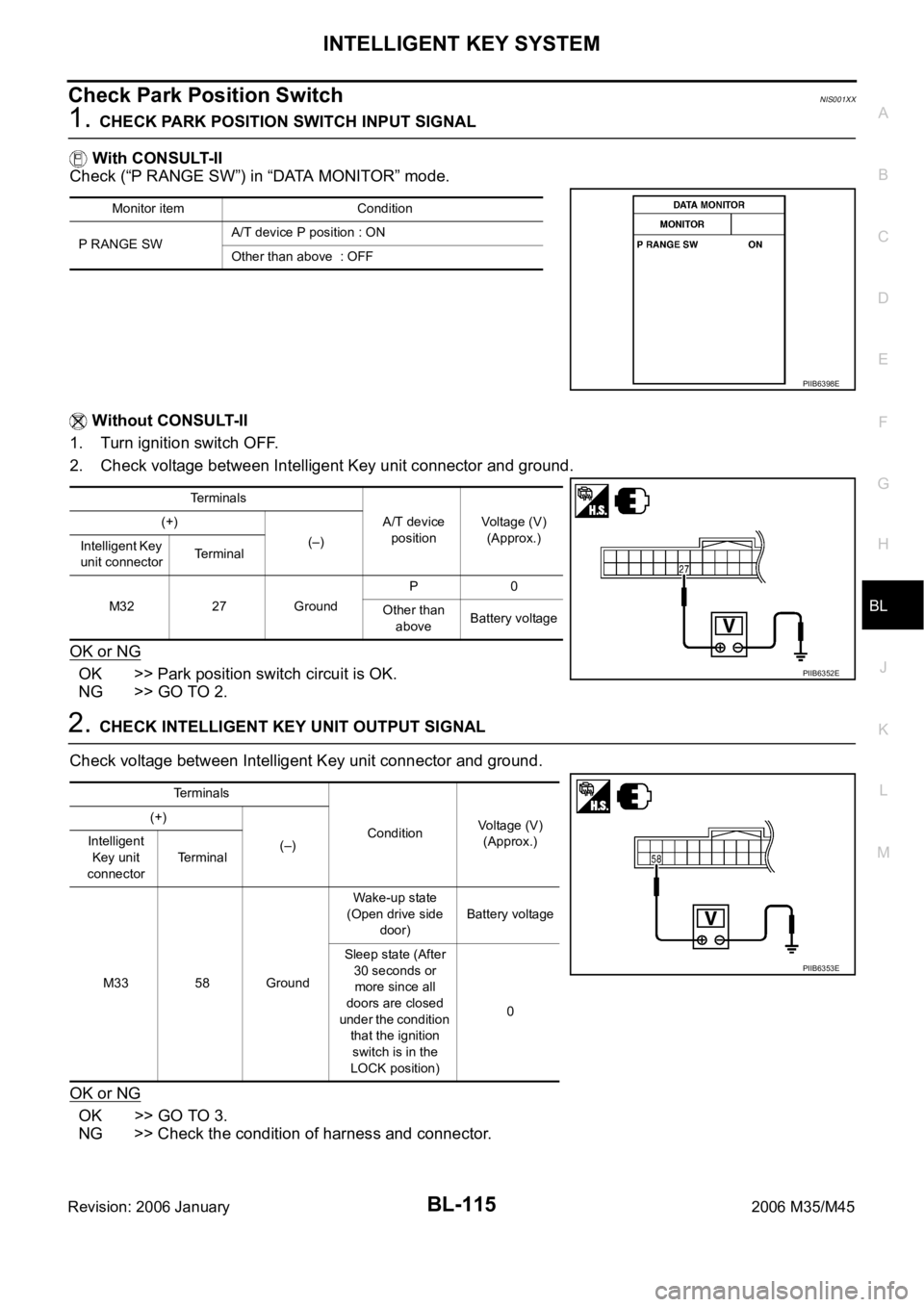
1. CHECK PARK POSITION SWITCH INPUT SIGNAL
With CONSULT-II
Check (“P RANGE SW”) in “DATA MONITOR” mode.
Without CONSULT-II
1. Turn ignition switch OFF.
2. Check voltage between Intelligent Key unit connector and ground.
OK or NG
OK >> Park position switch circuit is OK.
NG >> GO TO 2.
2. CHECK INTELLIGENT KEY UNIT OUTPUT SIGNAL
Check voltage between Intelligent Key unit connector and ground.
OK or NG
OK >> GO TO 3.
NG >> Check the condition of harness and connector.
Monitor item Condition
P RANGE SWA/T device P position : ON
Other than above : OFF
PIIB6398E
Te r m i n a l s
A/T device
positionVoltage (V)
(Approx.) (+)
(–)
Intelligent Key
unit connectorTerminal
M32 27 GroundP0
Other than
aboveBattery voltage
PIIB6352E
Terminals
ConditionVoltage (V)
(Approx.) (+)
(–) Intelligent
Key unit
connectorTerminal
M33 58 GroundWake-up state
(Open drive side
door)Battery voltage
Sleep state (After
30 seconds or
more since all
doors are closed
under the condition
that the ignition
switch is in the
LOCK position)0
PIIB6353E
Page 1068 of 5621
INTELLIGENT KEY SYSTEM/ENGINE START FUNCTION
BL-129
C
D
E
F
G
H
J
K
L
MA
B
BL
Revision: 2006 January2006 M35/M45
PRECAUTIONS FOR INTELLIGENT KEY SYSTEM
In the Intelligent Key system of model Y50, the transponder (the chip for immobilizer ID verifica-
tion) is integrated into the Intelligent Key. (For the conventional models, it is integrated into the
mechanical key.) Therefore, the mechanical key cannot perform the ID verification, and thus it can-
not start the engine. Instead of it, the immobilizer ID verification can be performed by inserting the
Intelligent Key into the key slot, and then it can start the engine.
When registering the Intelligent Key, 2 registration procedures (immobilizer ID registration and
Intelligent Key ID registration) should be performed. The immobilizer ID registration is the proce-
dure that registers the ID stored into the transponder (integrated into Intelligent Key) to the BCM.
The Intelligent Key ID registration is the procedure that registers the ID to the Intelligent Key unit.
Each registration is a different procedure.
When performing the Intelligent Key ID registration only, the engine cannot be started by inserting
the key into the key slot. When performing the engine immobilizer ID registration only, the engine
cannot be started by the operation when carrying the key. The registrations of both systems
should be performed.
Operation DescriptionNIS001Y9
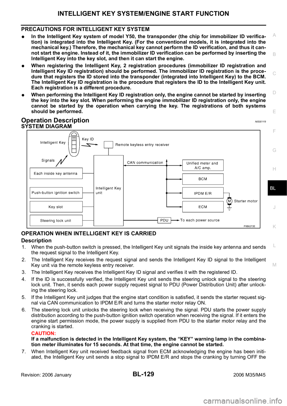
SYSTEM DIAGRAM
OPERATION WHEN INTELLIGENT KEY IS CARRIED
Description
1. When the push-button switch is pressed, the Intelligent Key unit signals the inside key antenna and sends
the request signal to the Intelligent Key.
2. The Intelligent Key receives the request signal and sends the Intelligent Key ID signal to the Intelligent
Key unit via the remote keyless entry receiver.
3. The Intelligent Key receives the Intelligent Key ID signal and verifies it with the registered ID.
4. If the ID is successfully verified, the Intelligent Key unit sends the steering unlock signal to the steering
lock unit. Then, it sends each power supply request signal to PDU (Power Distribution Unit) after unlock-
ing the steering lock.
5. If the Intelligent Key unit judges that the engine start condition is satisfied, it sends the starter request sig-
nal via CAN communication to IPDM E/R and turns the starter motor relay ON.
6. The steering lock unit unlocks the steering lock when receiving the signal. PDU starts the power supply
distribution according to the push-button ignition switch operation when receiving the signal. If it enters the
engine start permission mode, the power supply is supplied from PDU to the starter motor relay and the
cranking is started.
CAUTION:
If a malfunction is detected in the Intelligent Key system, the “KEY” warning lamp in the combina-
tion meter illuminates for 15 seconds. At that time, the engine cannot be started.
7. When Intelligent Key unit received feedback signal from ECM acknowledging the engine has been initi-
ated, the Intelligent Key unit sends a stop signal to IPDM E/R and stops the cranking by turning OFF the
PIIB6272E
Page 1091 of 5621

BL-152
INTELLIGENT KEY SYSTEM/ENGINE START FUNCTION
Revision: 2006 January2006 M35/M45
6. Select diagnosis mode. “WORK SUPPORT”, “SELF-DIAG
RESULTS”, “CAN DIAG SUPPORT MNTR”, “DATA MONITOR”,
“ACTIVE TEST” and “ECU PART NUMBER” are available.
CONSULT-II Application ItemsNIS001YM
SELF-DIAGNOSTIC RESULTS
How to Read SELF-DIAGNOSTIC RESULTS
BCIA0031E
PIIB6280E
Suspect Systems
[DTC]Diagnostic item is detected when... Repair work Reference page
CAN COMM 1
[U1000]Malfunction is detected in CAN communicationPerform CAN communi-
cation system inspectionBL-181
CAN COMM 2
[U1010]Malfunction is detected in CAN communication caused
by Intelligent Key unit internal malfunctionReplace Intelligent Key
unit.BL-181
STRG COMM 1
[B2013]Communication malfunction with steering lock unit is
detectedCheck steering lock unitBL-157
STEERING LOCK UNIT
[B2551]Even if the communication with steering lock unit is
normally performed, the steering lock is malfunctioningReplace steering lock
unitBL-159
INTELLIGENT KEY
[B2552]Internal malfunction is detected in Intelligent Key unitReplace Intelligent Key
unit.BL-163
IGN POWER CIRCUIT
[B2553]It continues for 2 seconds or more that ON power sup-
ply input to Intelligent Key unit is excessively low when
the power supply position is in ON positionCheck Intelligent Key
unit ON power supply
inputBL-163
ACC POWER CIRCUIT
[B2554]It continues for 2 seconds or more that ACC power
supply input to Intelligent Key unit is excessively low
when the power supply position is in ACC or ON posi-
tionCheck Intelligent Key
unit ACC power supply
inputBL-164
STOP LAMP CIRCUIT
[B2555]5V or less is detected at both the stop lamp switch sig-
nal input circuit that is input to Intelligent Key unit and
the monitor input before stop lamp switchCheck stop lamp switchBL-167
Page 1107 of 5621
BL-168
INTELLIGENT KEY SYSTEM/ENGINE START FUNCTION
Revision: 2006 January2006 M35/M45
DIAGNOSTIC PROCEDURE
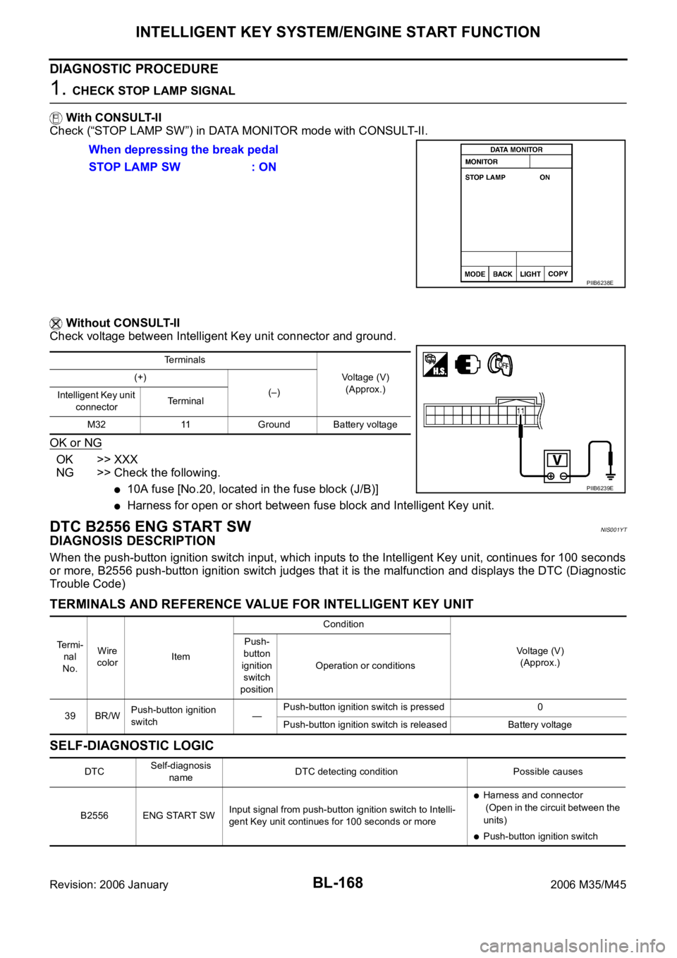
1. CHECK STOP LAMP SIGNAL
With CONSULT-II
Check (“STOP LAMP SW”) in DATA MONITOR mode with CONSULT-II.
Without CONSULT-II
Check voltage between Intelligent Key unit connector and ground.
OK or NG
OK >> XXX
NG >> Check the following.
10A fuse [No.20, located in the fuse block (J/B)]
Harness for open or short between fuse block and Intelligent Key unit.
DTC B2556 ENG START SWNIS001YT
DIAGNOSIS DESCRIPTION
When the push-button ignition switch input, which inputs to the Intelligent Key unit, continues for 100 seconds
or more, B2556 push-button ignition switch judges that it is the malfunction and displays the DTC (Diagnostic
Trouble Code)
TERMINALS AND REFERENCE VALUE FOR INTELLIGENT KEY UNIT
SELF-DIAGNOSTIC LOGIC
When depressing the break pedal
STOP LAMP SW : ON
PIIB6238E
Terminals
Voltage (V)
(Approx.) (+)
(–)
Intelligent Key unit
connectorTerminal
M32 11 Ground Battery voltage
PIIB6239E
Te r m i -
nal
No.Wire
colorItemCondition
Voltage (V)
(Approx.) Push-
button
ignition
switch
positionOperation or conditions
39 BR/WPush-button ignition
switch—Push-button ignition switch is pressed 0
Push-button ignition switch is released Battery voltage
DTCSelf-diagnosis
nameDTC detecting condition Possible causes
B2556 ENG START SWInput signal from push-button ignition switch to Intelli-
gent Key unit continues for 100 seconds or more
Harness and connector
(Open in the circuit between the
units)
Push-button ignition switch
Page 1153 of 5621
BL-214
TRUNK LID OPENER
Revision: 2006 January2006 M35/M45
CONSULT-II Function (BCM)NIS001ZR
CONSULT-II can display each diagnostic item using the diagnostic test modes shown following.
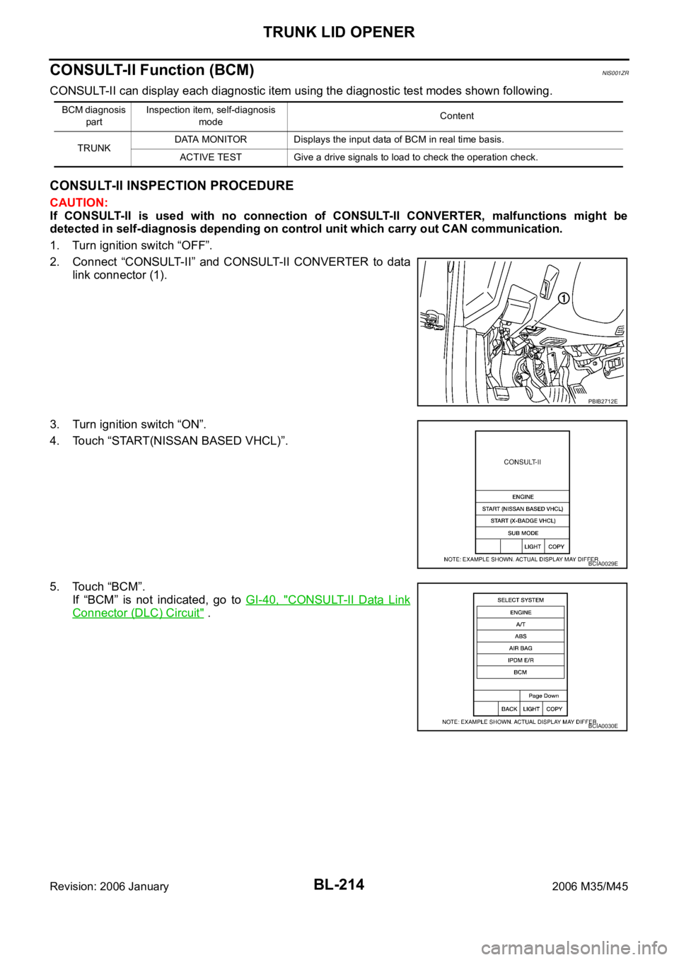
CONSULT-II INSPECTION PROCEDURE
CAUTION:
If CONSULT-II is used with no connection of CONSULT-II CONVERTER, malfunctions might be
detected in self-diagnosis depending on control unit which carry out CAN communication.
1. Turn ignition switch “OFF”.
2. Connect “CONSULT-II” and CONSULT-II CONVERTER to data
link connector (1).
3. Turn ignition switch “ON”.
4. Touch “START(NISSAN BASED VHCL)”.
5. Touch “BCM”.
If “BCM” is not indicated, go to GI-40, "
CONSULT-II Data Link
Connector (DLC) Circuit" .
BCM diagnosis
partInspection item, self-diagnosis
modeContent
TRUNKDATA MONITOR Displays the input data of BCM in real time basis.
ACTIVE TEST Give a drive signals to load to check the operation check.
PBIB2712E
BCIA0029E
BCIA0030E
Page 1173 of 5621
BL-234
VEHICLE SECURITY (THEFT WARNING) SYSTEM
Revision: 2006 January2006 M35/M45
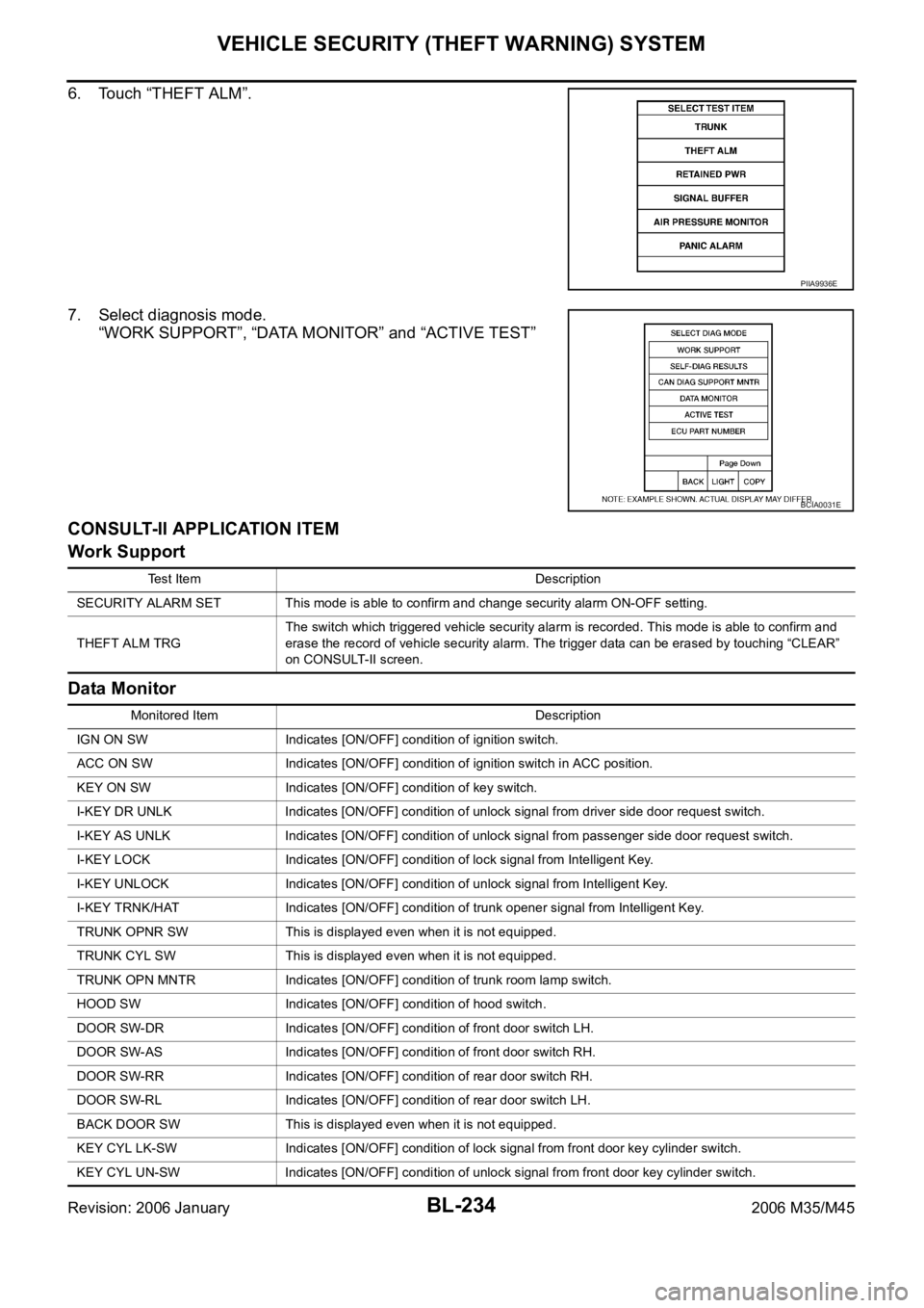
6. Touch “THEFT ALM”.
7. Select diagnosis mode.
“WORK SUPPORT”, “DATA MONITOR” and “ACTIVE TEST”
CONSULT-II APPLICATION ITEM
Work Support
Data Monitor
PIIA9936E
BCIA0031E
Test Item Description
SECURITY ALARM SET This mode is able to confirm and change security alarm ON-OFF setting.
THEFT ALM TRGThe switch which triggered vehicle security alarm is recorded. This mode is able to confirm and
erase the record of vehicle security alarm. The trigger data can be erased by touching “CLEAR”
on CONSULT-II screen.
Monitored Item Description
IGN ON SW Indicates [ON/OFF] condition of ignition switch.
ACC ON SW Indicates [ON/OFF] condition of ignition switch in ACC position.
KEY ON SW Indicates [ON/OFF] condition of key switch.
I-KEY DR UNLK Indicates [ON/OFF] condition of unlock signal from driver side door request switch.
I-KEY AS UNLK Indicates [ON/OFF] condition of unlock signal from passenger side door request switch.
I-KEY LOCK Indicates [ON/OFF] condition of lock signal from Intelligent Key.
I-KEY UNLOCK Indicates [ON/OFF] condition of unlock signal from Intelligent Key.
I-KEY TRNK/HAT Indicates [ON/OFF] condition of trunk opener signal from Intelligent Key.
TRUNK OPNR SW This is displayed even when it is not equipped.
TRUNK CYL SW This is displayed even when it is not equipped.
TRUNK OPN MNTR Indicates [ON/OFF] condition of trunk room lamp switch.
HOOD SW Indicates [ON/OFF] condition of hood switch.
DOOR SW-DR Indicates [ON/OFF] condition of front door switch LH.
DOOR SW-AS Indicates [ON/OFF] condition of front door switch RH.
DOOR SW-RR Indicates [ON/OFF] condition of rear door switch RH.
DOOR SW-RL Indicates [ON/OFF] condition of rear door switch LH.
BACK DOOR SW This is displayed even when it is not equipped.
KEY CYL LK-SW Indicates [ON/OFF] condition of lock signal from front door key cylinder switch.
KEY CYL UN-SW Indicates [ON/OFF] condition of unlock signal from front door key cylinder switch.
Page 1175 of 5621

BL-236
VEHICLE SECURITY (THEFT WARNING) SYSTEM
Revision: 2006 January2006 M35/M45
2. CHECK SECURITY INDICATOR LAMP
1. Lock doors using Intelligent Key or mechanical key.
2. Make sure security indicator lamp illuminate for 30 seconds.
Security indicator lamp should illuminate.
OK >> GO TO 3.
NG >> Perform diagnosis and repair. Refer to BL-238, "
Diagnostic Procedure 1" .
3. CHECK ALARM FUNCTION
1. After 30 seconds, security indicator lamp will start blink.
2. Open any door or hood before unlocking with Intelligent Key or mechanical key, or open trunk lid without
Intelligent Key or mechanical key.
Do alarm function properly.
OK >> GO TO 4.
NG >> Check the following.
The vehicle security system does not phase in alarm mode. Refer to BL-245, "Diagnostic Pro-
cedure 2" .
Alarm (horn, headlamp and hazard lamp) do not operate. Refer to BL-246, "Diagnostic Proce-
dure 3" .
4. CHECK ALARM CANCEL OPERATION
Unlock any door or open trunk lid useing Intelligent Key or mechanical key.
Alarm (horn, headlamp and hazard lamp) should stop.
OK >> INSPECTION END.
NG >> Perform diagnosis and repair. Refer to BL-246, "
Diagnostic Procedure 4" .
Page 1209 of 5621

BL-270
IVIS (INFINITI VEHICLE IMMOBILIZER SYSTEM-NATS)
Revision: 2006 January2006 M35/M45
CONSULT-II DIAGNOSTIC TEST MODE FUNCTION
NOTE:
When any initialization is performed, all ID previously registered will be erased and all NATS ignition keys
must be registered again.
The engine cannot be started with an unregistered key. In this case, the system will show “DIFFERENCE
OF KEY” or “LOCK MODE” as a self-diagnostic result on the CONSULT-II screen.
In rare case, “CHAIN OF ECM-IMMU” might be stored as a self-diagnostic result during key registration
procedure, even if the system is not malfunctioning.
HOW TO READ SELF-DIAGNOSTIC RESULTS
System Diagnosis mode DescriptionReference
page
NATS V5.0C/U INTIALIZATIONPerform registration again after repair, part replacement, and
additional key ID registration.
CAUTION:
“Control Unit Initialization” is activated only after per-
forming “Release steering lock”.Refer to the
Technical Bul-
letin.
SELF-DIAG RESULTS
Malfunctioning system stored in the ECM is displayed.
Printing the contents
Erasing the error recordBL-271
NATS BCM or S/ENTPIN READThe specified numbers of each control unit for acquisition of
password for control unit initialization are displayedRefer to the
Technical Bul-
letin.
STEERING LOCK
RELEASEIf the engine switch cannot be operated (the steering lock
cannot be released), release the steering lock forcibly and
make the engine switch operation possible.
CAUTION:
Always perform “Control Unit Initialization” and “Immo-
bilizer ID Registration” after performing “Release Steer-
ing Lock”.Refer to the
Technical Bul-
letin.
SELF-DIAG RESULTS
Malfunctioning system stored in the BCM is displayed.
Printing the contents
Erasing the error recordBL-271
NATS I-KEY SELF-DIAG RESULTS
Malfunctioning system stored in the Intelligent Key unit is
displayed.
Printing the contents
Erasing the error recordBL-272
PIIB6280E