Page 1372 of 5621
ACTUATOR AND ELECTRIC UNIT (ASSEMBLY)
BRC-61
[VDC/TCS/ABS]
C
D
E
G
H
I
J
K
L
MA
B
BRC
Revision: 2006 January2006 M35/M45
7. Remove ABS actuator and electric unit (control unit) from vehicle.
INSTALLATION
Installation is the reverse order of removal.
CAUTION:
When replacing ABS actuator and electric unit (control unit), make sure to adjust neutral position of
steering angle sensor. Refer to BRC-6, "
Adjustment of Steering Angle Sensor Neutral Position"
Page 1373 of 5621
BRC-62
[VDC/TCS/ABS]
G-SENSOR
Revision: 2006 January2006 M35/M45
G-SENSORPFP:47930
Removal and InstallationNFS000RD
CAUTION:
Do not drop or strike yaw rate/side G sensor, because it has little endurance to impact.
Do not use power tool etc., because yaw rate/side G sensor is sensitive for the impact.
REMOVAL
1. Remove center console. Refer to IP-10, "Component Parts
Drawing" .
2. Disconnect yaw rate/side G sensor harness connector.
3. Remove mounting bolts. Remove yaw rate/side G sensor.
(Shown in the figure 1).
INSTALLATION
Installation is the reverse order of removal.
SFIA2725J
Yaw rate/side G sensor mounting bolt
: 6.5 Nꞏm (0.66 kgꞏm, 58 in-lb)
Page 1374 of 5621
STEERING ANGLE SENSOR
BRC-63
[VDC/TCS/ABS]
C
D
E
G
H
I
J
K
L
MA
B
BRC
Revision: 2006 January2006 M35/M45
STEERING ANGLE SENSORPFP:25554
Removal and InstallationNFS000RE
REMOVAL
1. Remove spiral cable assembly. Refer to SRS-40, "SPIRAL CABLE" .
2. Remove steering angle sensor from spiral cable assembly.
INSTALLATION
Installation is the reverse order of removal.
CAUTION:
After work, make sure to adjust neutral position of steering angle sensor. Refer to BRC-6, "
Adjustment
of Steering Angle Sensor Neutral Position" .
SFIA1404E
Page 1375 of 5621
BRC-64
[VDC/TCS/ABS]
STEERING ANGLE SENSOR
Revision: 2006 January2006 M35/M45
Page 1405 of 5621
![INFINITI M35 2006 Factory Service Manual CO-30
[VQ35DE]
WATER INLET AND THERMOSTAT ASSEMBLY
Revision: 2006 January2006 M35/M45
INSPECTION AFTER REMOVAL
1. Check valve seating condition at ordinary room temperatures. It should seat tightly.
2 INFINITI M35 2006 Factory Service Manual CO-30
[VQ35DE]
WATER INLET AND THERMOSTAT ASSEMBLY
Revision: 2006 January2006 M35/M45
INSPECTION AFTER REMOVAL
1. Check valve seating condition at ordinary room temperatures. It should seat tightly.
2](/manual-img/42/57023/w960_57023-1404.png)
CO-30
[VQ35DE]
WATER INLET AND THERMOSTAT ASSEMBLY
Revision: 2006 January2006 M35/M45
INSPECTION AFTER REMOVAL
1. Check valve seating condition at ordinary room temperatures. It should seat tightly.
2. Check valve operation.
If the malfunctioning condition, when valve seating at ordinary
room temperature, or measured values are out of the standard,
replace water inlet and thermostat assembly.
INSTALLATION
Note the following, and install in the reverse order of removal.
Be careful not to spill engine coolant over engine room. Use rag to absorb engine coolant.
INSPECTION AFTER INSTALLATION
Check for leaks of engine coolant using the radiator cap tester adapter [SST: EG17650301 (J33984-A)]
and the radiator cap tester (commercial service tool). Refer to CO-11, "
LEAK CHECK" .
Start and warm up the engine. Visually make sure that there is no leaks of engine coolant.
Thermostat Standard
Valve opening temperature 82
C (180F)
Maximum valve lift 8.6 mm / 95
C (0.339 in / 203F)
Valve closing temperature 77
C (171F)
SLC949A
Page 1431 of 5621
![INFINITI M35 2006 Factory Service Manual CO-56
[VK45DE]
THERMOSTAT AND WATER CONTROL VALVE
Revision: 2006 January2006 M35/M45
5. Disconnect water suction hose from water inlet.
6. Remove water inlet and thermostat.
CAUTION:
Do not disassembl INFINITI M35 2006 Factory Service Manual CO-56
[VK45DE]
THERMOSTAT AND WATER CONTROL VALVE
Revision: 2006 January2006 M35/M45
5. Disconnect water suction hose from water inlet.
6. Remove water inlet and thermostat.
CAUTION:
Do not disassembl](/manual-img/42/57023/w960_57023-1430.png)
CO-56
[VK45DE]
THERMOSTAT AND WATER CONTROL VALVE
Revision: 2006 January2006 M35/M45
5. Disconnect water suction hose from water inlet.
6. Remove water inlet and thermostat.
CAUTION:
Do not disassemble thermostat.
7. Remove intake manifolds (upper and lower). Refer to EM-179, "
INTAKE MANIFOLD" .
8. Disconnect radiator hose (upper) from thermostat housing.
9. Disconnect heater hoses from water outlet and heater pipe.
10. Remove thermostat housing, water outlet pipe, water connector, water control valve, water outlet and
heater pipe.
CAUTION:
Do not disassemble water control valve.
INSPECTION AFTER REMOVAL
Make sure that valves both in thermostat and water control valve are completely closing at normal tempar-
ature.
Place a thread so that it is caught in the valves of the thermostat
and water control valve. Immerse fully in a container filled with
water. Heat while stirring. (The example in the figure shows ther-
mostat.)
The valve opening temperature is the temperature at which the
valve opens and falls from the thread.
Continue heating. Check the maximum valve lift.
NOTE:
The maximum valve lift standard temperature for water control
valve is the reference value.
After checking the maximum valve lift, lower the water tempera-
ture and check the valve closing temperature.
Standard values:
If the malfunctioning condition, when closing valve at normal temperature, or measured values are out of
the standard, replace thermostat and/or water control valve.
INSTALLATION
Note the following, and install in the reverse order of removal.
CAUTION:
Be careful not to spill engine coolant over engine room. Use rag to absorb engine coolant.
Thermostat and Water Control Valve
Install thermostat and water control valve with the whole circum-
ference of each flange part fit securely inside rubber ring. (The
example in the figure shows thermostat.)
SLC252B
Thermostat Water control valve
Valve opening temperature 80 - 84
C (176 - 183F) 93.5 - 96.5C (200 - 206F)
Maximum valve liftMore than 10 mm/ 95
C
(0.39 in/ 203
F)More than 8 mm/ 108
C
(0.315 in/ 226
F)
Valve closing temperature 77
C (171F) 90C (194F)
PBIC0157E
Page 1439 of 5621

DI-6
COMBINATION METERS
Revision: 2006 January2006 M35/M45
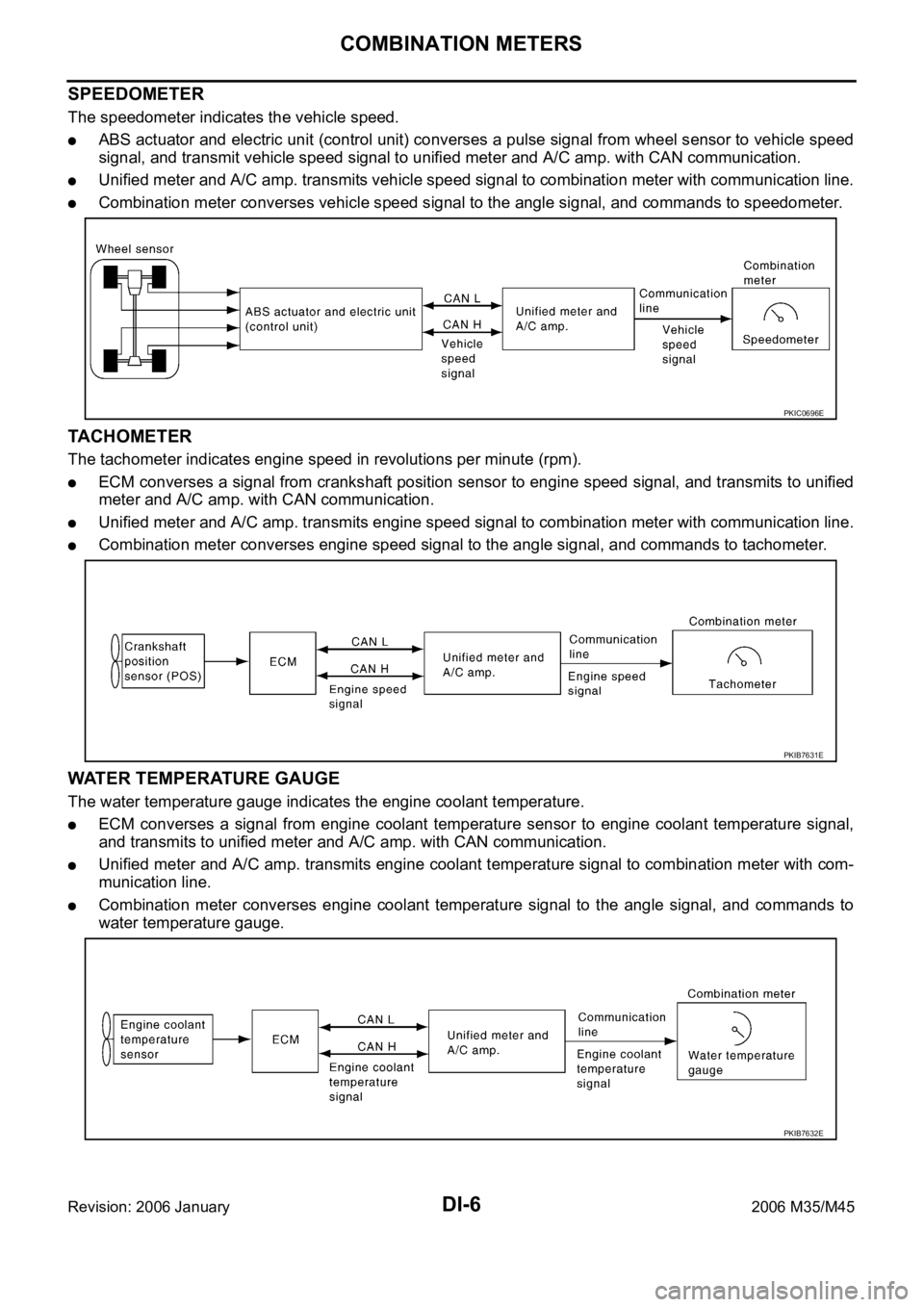
SPEEDOMETER
The speedometer indicates the vehicle speed.
ABS actuator and electric unit (control unit) converses a pulse signal from wheel sensor to vehicle speed
signal, and transmit vehicle speed signal to unified meter and A/C amp. with CAN communication.
Unified meter and A/C amp. transmits vehicle speed signal to combination meter with communication line.
Combination meter converses vehicle speed signal to the angle signal, and commands to speedometer.
TACHOMETER
The tachometer indicates engine speed in revolutions per minute (rpm).
ECM converses a signal from crankshaft position sensor to engine speed signal, and transmits to unified
meter and A/C amp. with CAN communication.
Unified meter and A/C amp. transmits engine speed signal to combination meter with communication line.
Combination meter converses engine speed signal to the angle signal, and commands to tachometer.
WATER TEMPERATURE GAUGE
The water temperature gauge indicates the engine coolant temperature.
ECM converses a signal from engine coolant temperature sensor to engine coolant temperature signal,
and transmits to unified meter and A/C amp. with CAN communication.
Unified meter and A/C amp. transmits engine coolant temperature signal to combination meter with com-
munication line.
Combination meter converses engine coolant temperature signal to the angle signal, and commands to
water temperature gauge.
PKIC0696E
PKIB7631E
PKIB7632E
Page 1440 of 5621

COMBINATION METERS
DI-7
C
D
E
F
G
H
I
J
L
MA
B
DI
Revision: 2006 January2006 M35/M45
FUEL GAUGE
The fuel gauge indicates the approximate fuel level in the fuel tank.
The fuel gauge is regulated by a variable ground signal supplied
from unified meter and A/C amp. terminal 58
through the fuel level sensor unit and fuel pump (main) terminals 5 and 2, and
through the fuel level sensor unit (sub) terminals 2 and 1
to unified meter and A/C amp. terminal 42.
Unified meter and A/C amp. provides a fuel level signal to combination meter for fuel gauge with communica-
tion line between unified meter and A/C amp. and combination meter.
ODO/TRIP METER
ABS actuator and electric unit (control unit) converses a pulse signal from wheel sensor to vehicle speed
signal, and transmits vehicle speed signal to unified meter and A/C amp. with CAN communication.
Unified meter and A/C amp. converses vehicle speed signal to 8 pulse signal, and transmits to combina-
tion meter.
Combination meter processes the 8 pulse signal and the memory signals from the meter memory circuit.
Then the mileage is displayed.
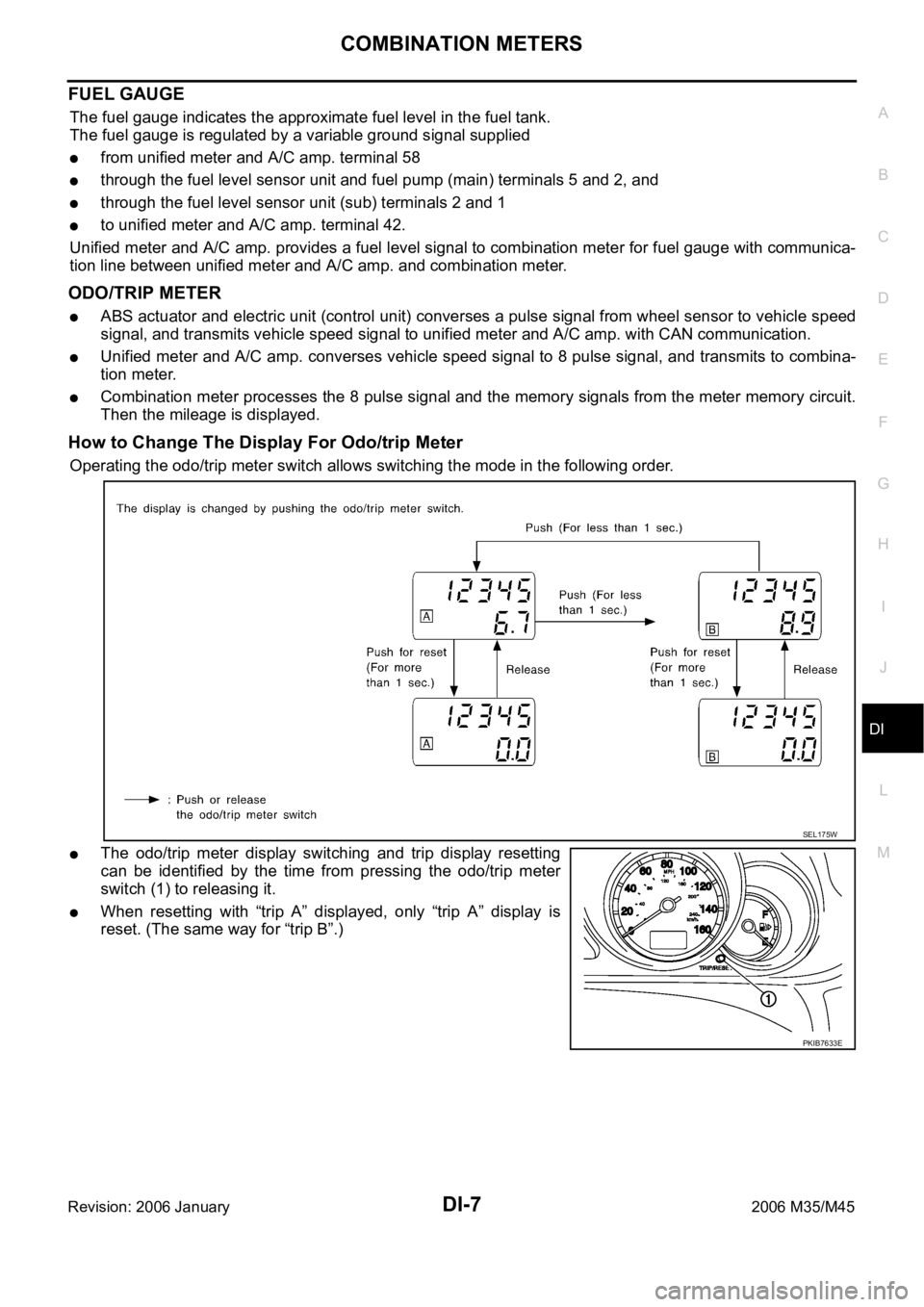
How to Change The Display For Odo/trip Meter
Operating the odo/trip meter switch allows switching the mode in the following order.
The odo/trip meter display switching and trip display resetting
can be identified by the time from pressing the odo/trip meter
switch (1) to releasing it.
When resetting with “trip A” displayed, only “trip A” display is
reset. (The same way for “trip B”.)
SEL175W
PKIB7633E