Page 4867 of 5621

PG-40
PDU (POWER DISTRIBUTION UNIT)
Revision: 2006 January2006 M35/M45
Check PDU Power Supply and Ground CircuitNKS004EL
1. CHECK POWER SUPPLY CIRCUIT
1. Turn ignition switch OFF.
2. Disconnect PDU connector.
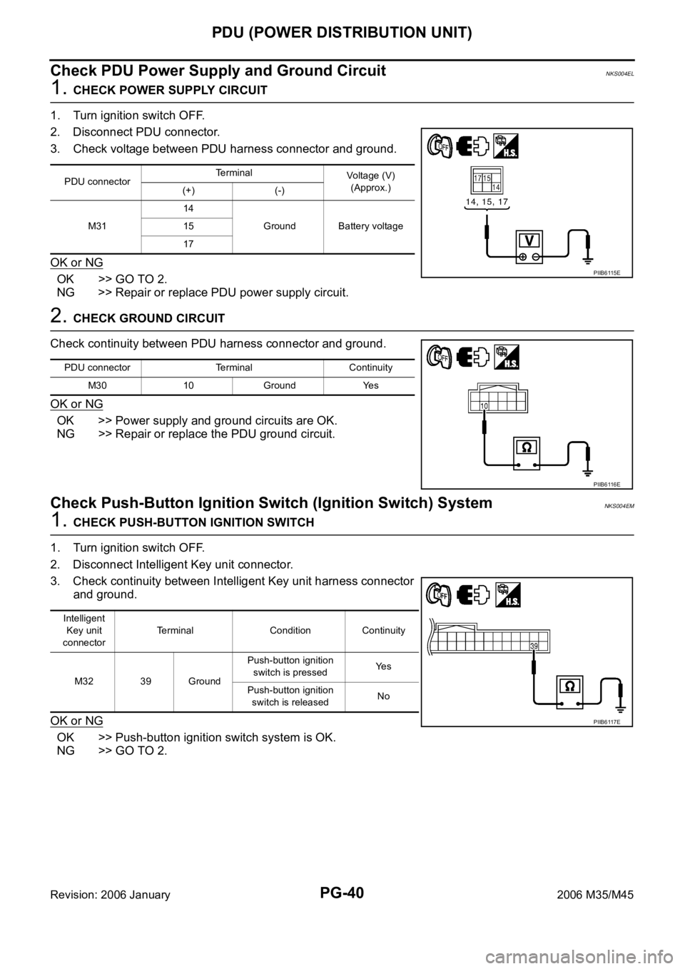
3. Check voltage between PDU harness connector and ground.
OK or NG
OK >> GO TO 2.
NG >> Repair or replace PDU power supply circuit.
2. CHECK GROUND CIRCUIT
Check continuity between PDU harness connector and ground.
OK or NG
OK >> Power supply and ground circuits are OK.
NG >> Repair or replace the PDU ground circuit.
Check Push-Button Ignition Switch (Ignition Switch) SystemNKS004EM
1. CHECK PUSH-BUTTON IGNITION SWITCH
1. Turn ignition switch OFF.
2. Disconnect Intelligent Key unit connector.
3. Check continuity between Intelligent Key unit harness connector
and ground.
OK or NG
OK >> Push-button ignition switch system is OK.
NG >> GO TO 2.
PDU connectorTerminal
Voltage (V)
(Approx.)
(+) (-)
M3114
Ground Battery voltage 15
17
PIIB6115E
PDU connector Terminal Continuity
M30 10 Ground Yes
PIIB6116E
Intelligent
Key unit
connectorTerminal Condition Continuity
M32 39 GroundPush-button ignition
switch is pressedYe s
Push-button ignition
switch is releasedNo
PIIB6117E
Page 4869 of 5621

PG-42
PDU (POWER DISTRIBUTION UNIT)
Revision: 2006 January2006 M35/M45
Check Push-Button Ignition Switch (Indicator Circuit) SystemNKS004EN
1. CHECK PUSH-BUTTON IGNITION SWITCH INDICATOR SYSTEM
1. Turn ignition switch OFF.
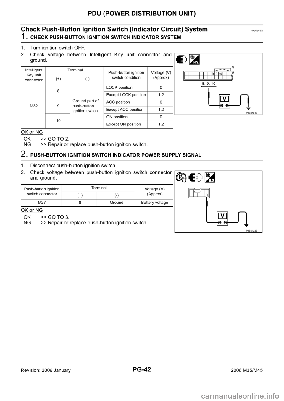
2. Check voltage between Intelligent Key unit connector and
ground.
OK or NG
OK >> GO TO 2.
NG >> Repair or replace push-button ignition switch.
2. PUSH-BUTTON IGNITION SWITCH INDICATOR POWER SUPPLY SIGNAL
1. Disconnect push-button ignition switch.
2. Check voltage between push-button ignition switch connector
and ground.
OK or NG
OK >> GO TO 3.
NG >> Repair or replace push-button ignition switch.
Intelligent
Key unit
connectorTe r m i n a l
Push-button ignition
switch conditionVoltage (V)
(Approx)
(+) (-)
M328
Ground part of
push-button
ignition switchLOCK position 0
Except LOCK position 1.2
9ACC position 0
Except ACC position 1.2
10ON position 0
Except ON position 1.2
PIIB6121E
Push-button ignition
switch connectorTerminal
Voltage (V)
(Approx)
(+) (-)
M27 8 Ground Battery voltage
PIIB6122E
Page 4870 of 5621

PDU (POWER DISTRIBUTION UNIT)
PG-43
C
D
E
F
G
H
I
J
L
MA
B
PG
Revision: 2006 January2006 M35/M45
3. PUSH-BUTTON IGNITION SWITCH INDICATOR GROUND CIRCUIT
1. Disconnect Intelligent Key unit connector.
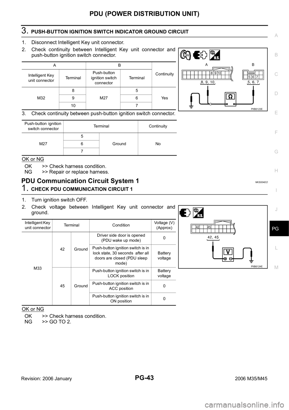
2. Check continuity between Intelligent Key unit connector and
push-button ignition switch connector.
3. Check continuity between push-button ignition switch connector.
OK or NG
OK >> Check harness condition.
NG >> Repair or replace harness.
PDU Communication Circuit System 1NKS004EO
1. CHECK PDU COMMUNICATION CIRCUIT 1
1. Turn ignition switch OFF.
2. Check voltage between Intelligent Key unit connector and
ground.
OK or NG
OK >> Check harness condition.
NG >> GO TO 2.
AB
Continuity
Intelligent Key
unit connectorTerminalPush-button
ignition switch
connectorTe r m i n a l
M328
M275
Ye s 96
10 7
P u s h - b u t t o n i g n i t i o n
switch connectorTerminal Continuity
M275
Ground No 6
7
PIIB6123E
Intelligent Key
unit connectorTerminal ConditionVoltage (V)
(Approx)
M3342 GroundDriver side door is opened
(PDU wake up mode)0
Push-button ignition switch is in
lock state, 30 seconds after all
doors are closed (PDU sleep
mode)Battery
voltage
45 GroundPush-button ignition switch is in
LOCK positionBattery
voltage
Push-button ignition switch is in
ACC position0
Push-button ignition switch is in
ON position0
PIIB6124E
Page 4881 of 5621
PG-54
GROUND
Revision: 2006 January2006 M35/M45
Battery Cable
CKIT0674E
Page 4902 of 5621
HARNESS
PG-75
C
D
E
F
G
H
I
J
L
MA
B
PG
Revision: 2006 January2006 M35/M45
Battery Cable (2WD Models with VQ Engine)
TKIT0452E
Page 4903 of 5621
PG-76
HARNESS
Revision: 2006 January2006 M35/M45
Battery Cable (AWD Models with VQ Engine)
TKIT0453E
Page 4904 of 5621
HARNESS
PG-77
C
D
E
F
G
H
I
J
L
MA
B
PG
Revision: 2006 January2006 M35/M45
Battery Cable (VK Engine)
TKIT0454E
Page 4920 of 5621

HARNESS
PG-93
C
D
E
F
G
H
I
J
L
MA
B
PG
Revision: 2006 January2006 M35/M45
Wiring Diagram Codes (Cell Codes) NKS004ET
Use the chart below to find out what each wiring diagram code stands for.
Refer to the wiring diagram code in the alphabetical index to find the location (page number) of each wiring
diagram.
Code Section Wiring Diagram Name
A/C ATC Air Conditioner
AF1B1 EC Air Fuel Ratio Sensor 1 Bank 1
AF1B2 EC Air Fuel Ratio Sensor 1 Bank 2
AF1HB1 EC Air Fuel Ratio Sensor 1 Heater Bank 1
AF1HB2 EC Air Fuel Ratio Sensor 1 Heater Bank 2
AFS LT Adaptive Front Lighting System
APPS1 EC Accelerator Pedal Position Sensor
APPS2 EC Accelerator Pedal Position Sensor
APPS3 EC Accelerator Pedal Position Sensor
ASC/BS EC Automatic Speed Control Device (ASCD) Brake Switch
ASC/SW EC Automatic Speed Control Device (ASCD) Steering Switch
ASCBOF EC Automatic Speed Control Device (ASCD) Brake Switch
ASCIND EC Automatic Speed Control Device (ASCD) Indicator
AT/IND DI A/T Indicator Lamp
AUT/DP SE Automatic Drive Positioner
AUTO/L LT Automatic Light System
AV AV Audio and Visual System
AWD TF AWD Control System
BACK/L LT Back-Up Lamp
BRK/SW EC Brake Switch
C/SEAT SE Climate Controlled Seat
CAN AT CAN Communication Line
CAN EC CAN Communication Line
CAN LAN CAN System
CHARGE SC Charging System
CHIME DI Warning Chime
CIGAR WW Cigarette Lighter
CLOCK DI Clock
COMBSW LT Combination Switch
COMPAS DI Compass and Thermometer
COOL/F EC Cooling Fan Control
CUR/SE EC Battery Current Sensor
D/LOCK BL Power Door Lock
DEF GW Rear Window Defogger
DTRL LT Headlamp - with Daytime Light System
ECM/PW EC ECM Power Supply for Back-Up
ECTS EC Engine Coolant Temperature Sensor
ENG/ST BL Engine Start System
EPS STC Electric Controlled Power Steering System
ETC1 EC Electric Throttle Control Function
ETC2 EC Electric Throttle Control Motor Relay