2006 INFINITI M35 ground
[x] Cancel search: groundPage 3503 of 5621
GI-40
CONSULT-II CHECKING SYSTEM
Revision: 2006 January2006 M35/M45
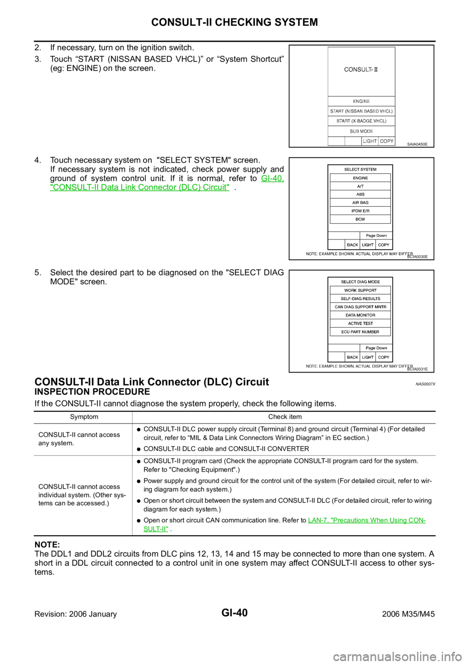
2. If necessary, turn on the ignition switch.
3. Touch “START (NISSAN BASED VHCL)” or “System Shortcut”
(eg: ENGINE) on the screen.
4. Touch necessary system on "SELECT SYSTEM" screen.
If necessary system is not indicated, check power supply and
ground of system control unit. If it is normal, refer to GI-40,
"CONSULT-II Data Link Connector (DLC) Circuit" .
5. Select the desired part to be diagnosed on the "SELECT DIAG
MODE" screen.
CONSULT-II Data Link Connector (DLC) CircuitNAS0007X
INSPECTION PROCEDURE
If the CONSULT-II cannot diagnose the system properly, check the following items.
NOTE:
The DDL1 and DDL2 circuits from DLC pins 12, 13, 14 and 15 may be connected to more than one system. A
short in a DDL circuit connected to a control unit in one system may affect CONSULT-II access to other sys-
tems.
SAIA0450E
BCIA0030E
BCIA0031E
Symptom Check item
CONSULT-II cannot access
any system.
CONSULT-II DLC power supply circuit (Terminal 8) and ground circuit (Terminal 4) (For detailed
circuit, refer to “MIL & Data Link Connectors Wiring Diagram” in EC section.)
CONSULT-II DLC cable and CONSULT-II CONVERTER
CONSULT-II cannot access
individual system. (Other sys-
tems can be accessed.)
CONSULT-II program card (Check the appropriate CONSULT-II program card for the system.
Refer to "Checking Equipment".)
Power supply and ground circuit for the control unit of the system (For detailed circuit, refer to wir-
ing diagram for each system.)
Open or short circuit between the system and CONSULT-II DLC (For detailed circuit, refer to wiring
diagram for each system.)
Open or short circuit CAN communication line. Refer to LAN-7, "Precautions When Using CON-
SULT-II" .
Page 3505 of 5621
GI-42
LIFTING POINT
Revision: 2006 January2006 M35/M45
LIFTING POINTPFP:00000
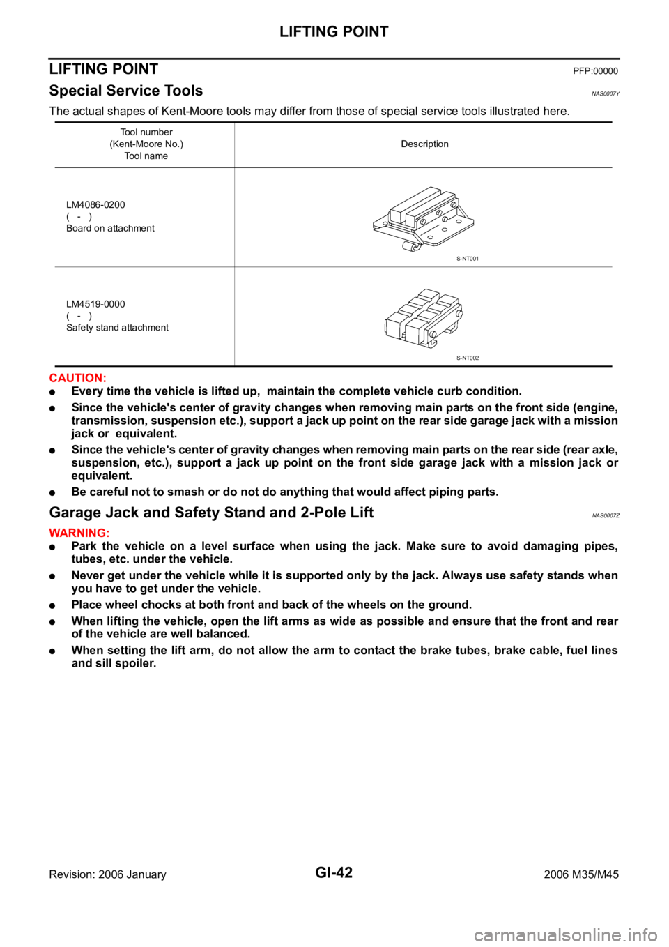
Special Service Tools NAS0007Y
The actual shapes of Kent-Moore tools may differ from those of special service tools illustrated here.
CAUTION:
Every time the vehicle is lifted up, maintain the complete vehicle curb condition.
Since the vehicle's center of gravity changes when removing main parts on the front side (engine,
transmission, suspension etc.), support a jack up point on the rear side garage jack with a mission
jack or equivalent.
Since the vehicle's center of gravity changes when removing main parts on the rear side (rear axle,
suspension, etc.), support a jack up point on the front side garage jack with a mission jack or
equivalent.
Be careful not to smash or do not do anything that would affect piping parts.
Garage Jack and Safety Stand and 2-Pole LiftNAS0007Z
WAR NING :
Park the vehicle on a level surface when using the jack. Make sure to avoid damaging pipes,
tubes, etc. under the vehicle.
Never get under the vehicle while it is supported only by the jack. Always use safety stands when
you have to get under the vehicle.
Place wheel chocks at both front and back of the wheels on the ground.
When lifting the vehicle, open the lift arms as wide as possible and ensure that the front and rear
of the vehicle are well balanced.
When setting the lift arm, do not allow the arm to contact the brake tubes, brake cable, fuel lines
and sill spoiler.
Tool number
(Kent-Moore No.)
Tool nameDescription
LM4086-0200
( - )
Board on attachment
LM4519-0000
( - )
Safety stand attachment
S-NT001
S-NT002
Page 3507 of 5621
GI-44
TOW TRUCK TOWING
Revision: 2006 January2006 M35/M45
TOW TRUCK TOWINGPFP:00000
Tow Truck TowingNAS00081
CAUTION:
All applicable state or Provincial (in Canada) laws and local laws regarding the towing operation
must be obeyed.
It is necessary to use proper towing equipment to avoid possible damage to the vehicle during
towing operation. Towing is in accordance with Towing Procedure Manual at dealer.
Always attach safety chains before towing.
When towing, make sure that the transmission, steering system and powertrain are in good order.
If any unit is damaged, dollies must be used.
Never tow an automatic transmission model from the rear (that is backward) with four wheels on
the ground. This may cause serious and expensive damage to the transmission.
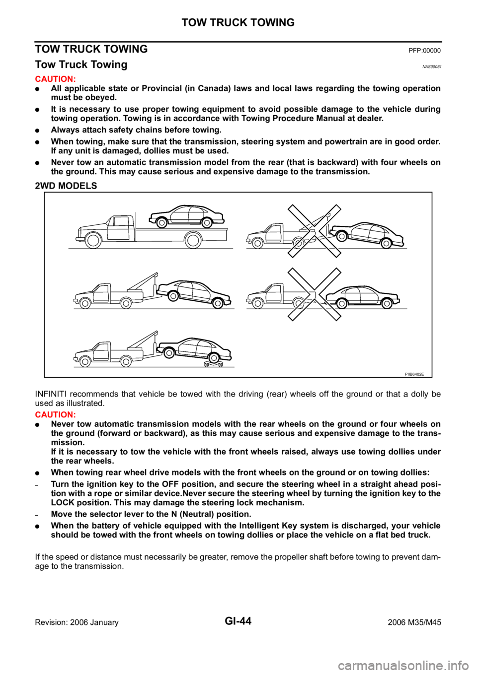
2WD MODELS
INFINITI recommends that vehicle be towed with the driving (rear) wheels off the ground or that a dolly be
used as illustrated.
CAUTION:
Never tow automatic transmission models with the rear wheels on the ground or four wheels on
the ground (forward or backward), as this may cause serious and expensive damage to the trans-
mission.
If it is necessary to tow the vehicle with the front wheels raised, always use towing dollies under
the rear wheels.
When towing rear wheel drive models with the front wheels on the ground or on towing dollies:
–Turn the ignition key to the OFF position, and secure the steering wheel in a straight ahead posi-
tion with a rope or similar device.Never secure the steering wheel by turning the ignition key to the
LOCK position. This may damage the steering lock mechanism.
–Move the selector lever to the N (Neutral) position.
When the battery of vehicle equipped with the Intelligent Key system is discharged, your vehicle
should be towed with the front wheels on towing dollies or place the vehicle on a flat bed truck.
If the speed or distance must necessarily be greater, remove the propeller shaft before towing to prevent dam-
age to the transmission.
PIIB6402E
Page 3508 of 5621
TOW TRUCK TOWING
GI-45
C
D
E
F
G
H
I
J
K
L
MB
GI
Revision: 2006 January2006 M35/M45
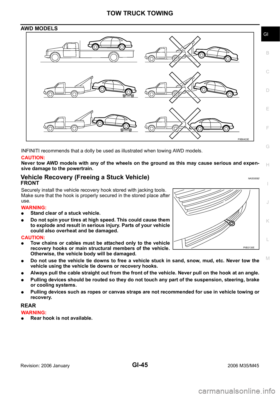
AWD MODELS
INFINITI recommends that a dolly be used as illustrated when towing AWD models.
CAUTION:
Never tow AWD models with any of the wheels on the ground as this may cause serious and expen-
sive damage to the powertrain.
Vehicle Recovery (Freeing a Stuck Vehicle) NAS00082
FRONT
Securely install the vehicle recovery hook stored with jacking tools.
Make sure that the hook is properly secured in the stored place after
use.
WAR NING :
Stand clear of a stuck vehicle.
Do not spin your tires at high speed. This could cause them
to explode and result in serious injury. Parts of your vehicle
could also overheat and be damaged.
CAUTION:
Tow chains or cables must be attached only to the vehicle
recovery hooks or main structural members of the vehicle.
Otherwise, the vehicle body will be damaged.
Do not use the vehicle tie downs to free a vehicle stuck in sand, snow, mud, etc. Never tow the
vehicle using the vehicle tie downs or recovery hooks.
Always pull the cable straight out from the front of the vehicle. Never pull on the hook at an angle.
Pulling devices should be routed so they do not touch any part of the suspension, steering, brake
or cooling systems.
Pulling devices such as ropes or canvas straps are not recommended for use in vehicle towing or
recovery.
REAR
WAR NING :
Rear hook is not available.
PIIB6403E
PIIB3130E
Page 3520 of 5621
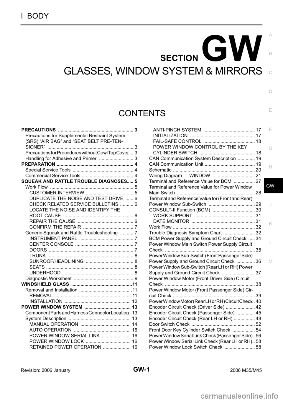
GW-1
GLASSES, WINDOW SYSTEM & MIRRORS
I BODY
CONTENTS
C
D
E
F
G
H
J
K
L
M
SECTION GW
A
B
GW
Revision: 2006 January2006 M35/M45
GLASSES, WINDOW SYSTEM & MIRRORS
PRECAUTIONS .......................................................... 3
Precautions for Supplemental Restraint System
(SRS) “AIR BAG” and “SEAT BELT PRE-TEN-
SIONER” .................................................................. 3
Precautions for Procedures without Cowl Top Cover ..... 3
Handling for Adhesive and Primer ........................... 3
PREPARATION ........................................................... 4
Special Service Tools ............................................... 4
Commercial Service Tools ........................................ 4
SQUEAK AND RATTLE TROUBLE DIAGNOSES ..... 5
Work Flow ................................................................ 5
CUSTOMER INTERVIEW ..................................... 5
DUPLICATE THE NOISE AND TEST DRIVE ....... 6
CHECK RELATED SERVICE BULLETINS ........... 6
LOCATE THE NOISE AND IDENTIFY THE
ROOT CAUSE ...................................................... 6
REPAIR THE CAUSE ........................................... 6
CONFIRM THE REPAIR ....................................... 7
Generic Squeak and Rattle Troubleshooting ........... 7
INSTRUMENT PANEL .......................................... 7
CENTER CONSOLE ............................................. 7
DOORS ................................................................. 7
TRUNK .................................................................. 8
SUNROOF/HEADLINING ..................................... 8
SEATS ................................................................... 8
UNDERHOOD ....................................................... 8
Diagnostic Worksheet .............................................. 9
WINDSHIELD GLASS ...............................................11
Removal and Installation ......................................... 11
REMOVAL ........................................................
.... 11
INSTALLATION ................................................... 12
POWER WINDOW SYSTEM .................................... 13
Component Parts and Harness Connector Location ... 13
System Description ................................................ 13
MANUAL OPERATION ....................................... 14
AUTO OPERATION ............................................ 16
POWER WINDOW SERIAL LINK ....................... 16
POWER WINDOW LOCK ................................... 16
RETAINED POWER OPERATION ...................... 16ANTI-PINCH SYSTEM ........................................ 17
INITIALIZATION .................................................. 17
FAIL-SAFE CONTROL ........................................ 18
POWER WINDOW CONTROL BY THE KEY
CYLINDER SWITCH ........................................... 18
CAN Communication System Description .............. 19
CAN Communication Unit ....................................... 19
Schematic ............................................................... 20
Wiring Diagram — WINDOW — ............................. 21
Terminal and Reference Value for BCM ................. 27
Terminal and Reference Value for Power Window
Main Switch ............................................................ 28
Terminal and Reference Value for (Front and Rear)
Power Window Sub-Switch .................................... 29
CONSULT-II Function (BCM) ................................. 30
WORK SUPPORT ............................................... 31
DATE MONITOR ................................................. 31
Work Flow ............................................................... 32
Trouble Diagnosis Symptom Chart ......................... 32
BCM Power Supply and Ground Circuit Check ...... 34
Power Window Main Switch Power Supply Circuit
Check ..................................................................... 35
Power Window Sub-Switch (Front Passenger Side)
Power Supply and Ground Circuit Check ............... 36
Power Window Sub-Switch (Rear LH or RH) Power
Supply and Ground Circuit Check .......................... 37
Power Window Motor (Front Driver Side) Circuit
Check ..................................................................... 38
Power Window Motor (Front Passenger Side) Cir-
cuit Check ............................................................... 39
Power Window Motor (Rear LH or RH) Circuit Check ... 40
Encoder Circuit Check (Driver Side) ....................... 42
Encoder Circuit Check (Passenger Side) ............... 45
Encoder Circuit Check (Rear LH or RH) ................. 48
Door Switch Check ..............................................
... 52
Front Door Key Cylinder Switch Check .................. 54
Power Window Serial Link Check (Passenger Side) ... 56
Power Window Serial Link Check (Rear LH or RH) ... 58
Power Window Lock Switch Check ........................ 58
Page 3521 of 5621

GW-2Revision: 2006 January2006 M35/M45 SIDE WINDOW GLASS ............................................ 59
Removal and Installation ........................................ 59
REMOVAL ........................................................
... 59
INSTALLATION .................................................... 60
REAR WINDOW GLASS AND MOLDING ................ 61
Removal and Installation ........................................ 61
REMOVAL ........................................................
... 61
INSTALLATION .................................................... 62
FRONT DOOR GLASS AND REGULATOR ............. 63
Removal and Installation ........................................ 63
DOOR GLASS ..................................................... 63
REGULATOR ASSEMBLY .................................. 64
Disassembly and Assembly .................................... 65
REGULATOR ASSEMBLY .................................. 65
Inspection after Installation ..................................... 65
SYSTEM INITIALIZATION ................................... 65
INSPECT THE FUNCTION OF THE ANTI-
PINCH SYSTEM. ................................................. 65
FITTING INSPECTION ........................................ 66
REAR DOOR GLASS AND REGULATOR ............... 67
Removal and Installation ........................................ 67
DOOR GLASS ..................................................... 67
REGULATOR ASSEMBLY .................................. 68
Disassembly and Assembly .................................... 70
REGULATOR ASSEMBLY .................................. 70
Inspection after Installation ..................................... 70
SYSTEM INITIALIZATION ................................... 70
INSPECT THE FUNCTION OF THE ANTI-
PINCH SYSTEM .................................................. 70
FITTING INSPECTION ........................................ 70
INSIDE MIRROR ....................................................... 71
Wiring Diagram –I/MIRR– ....................................... 71
Removal and Installation ........................................ 72
REMOVAL ........................................................
... 72
INSTALLATION .................................................... 72
REAR WINDOW DEFOGGER .................................. 73
Component Parts and Harness Connector Location ... 73
System Description ................................................. 73
CAN Communication System Description .............. 75
CAN Communication Unit ....................................... 75
Schematic ............................................................... 76
Wiring Diagram — DEF — ..................................... 77
Terminal and Reference Value for BCM ................. 81
Terminal and Reference Value for IPDM E/R ......... 81
CONSULT-II Inspection Procedure ......................... 82
DATA MONITOR .................................................. 83
ACTIVE TEST ..................................................... 83
Work Flow ............................................................... 84Trouble Diagnoses Symptom Chart .....................
... 84
BCM Power Supply and Ground Circuit Check ...... 85
Rear Window Defogger Switch Circuit Check ......... 86
Rear Window Defogger Power Supply Circuit
Check ...................................................................... 86
Rear Window Defogger Circuit Check .................... 88
Door Mirror Defogger Power Supply Circuit Check ... 89
Driver Side Door Mirror Defogger Circuit Check ..... 91
Passenger Side Door Mirror Defogger Circuit Check
... 92
Filament Check ....................................................... 94
Filament Repair ....................................................... 94
REPAIR EQUIPMENT ......................................... 94
REPAIRING PROCEDURE ................................. 95
REVERSE INTERLOCK DOOR MIRROR SYSTEM ... 96
Component Parts and Harness Connector Location ... 96
System Description ................................................. 96
OPERATION CONDITIONS ................................ 96
MIRROR UNGLE MEMORY FUNCTION ............ 96
REVERSE INTERLOCK DOOR MIRROR SYS-
TEM OPERATION ............................................... 97
CAN Communication System Description .............. 97
CAN Communication Unit ....................................... 97
Schematic ............................................................... 98
Wiring Diagram —MIRROR— ................................ 99
Terminals and Reference Values for Automatic
Drive Positioner Control Unit .................................104
Terminals and Reference Values for Driver Seat
Control Unit ...........................................................105
CONSULT-II Function (AUTO DRIVE POS.) ........106
CONSULT-II INSPECTION PROCEDURE ........106
DATA MONITOR ................................................107
ACTIVE TEST ....................................................107
Work Flow .............................................................108
Symptom Chart .....................................................108
Check Changeover Switch Circuit ........................109
Check Mirror Switch Circuit Check ....................... 111
Check Mirror Motor Circuit Check .........................113
Check Mirror Sensor Circuit Check .......................116
Check A/T Control Device R Position Circuit ........119
DOOR MIRROR .......................................................120
Automatic Drive Positioner Interlocking Door Mirror .120
Removal and Installation .......................................120
REMOVAL ..........................................................120
INSTALLATION ..................................................120
Disassembly and Assembly ..................................121
DISASSEMBLY ..................................................121
ASSEMBLY ........................................................122
Page 3533 of 5621

GW-14
POWER WINDOW SYSTEM
Revision: 2006 January2006 M35/M45
to BCM terminal 42.
With ignition switch in ON or START position,
Power is supplied
through 15A fuse [No. 1, located in the fuse block (J/B)]
to BCM terminal 38, and
through BCM terminal 53
to power window main switch terminal 10
Ground supplied
to BCM terminal 52
through body grounds M16 and M70.
to power window main switch terminal 17
through body grounds M16 and M70.
to power window sub-switch (front passenger side) terminal 11
through body grounds M16 and M70.
to power window sub-switch (rear LH and RH) terminal 11
through body grounds B5, B40 and B131.
MANUAL OPERATION
Front Driver Side Door
WINDOW UP
When the front LH switch in the power window main switch is pressed in the up position,
Power is supplied
through power window main switch terminal 8
to power window motor (front driver side) terminal 2.
Ground is supplied
to power window motor (front driver side) terminal 1
through power window main switch terminal 11.
Then, the motor raises the window until the switch is released.
WINDOW DOWN
When the front LH switch in the power window main switch is pressed in the down position
Power is supplied
through power window main switch terminal 11
to power window motor (front driver side) terminal 1.
Ground is supplied
to power window motor (front driver side) terminal 2
through power window main switch terminal 8.
Then, the motor lowers the window until the switch is released.
Page 3534 of 5621
POWER WINDOW SYSTEM
GW-15
C
D
E
F
G
H
J
K
L
MA
B
GW
Revision: 2006 January2006 M35/M45
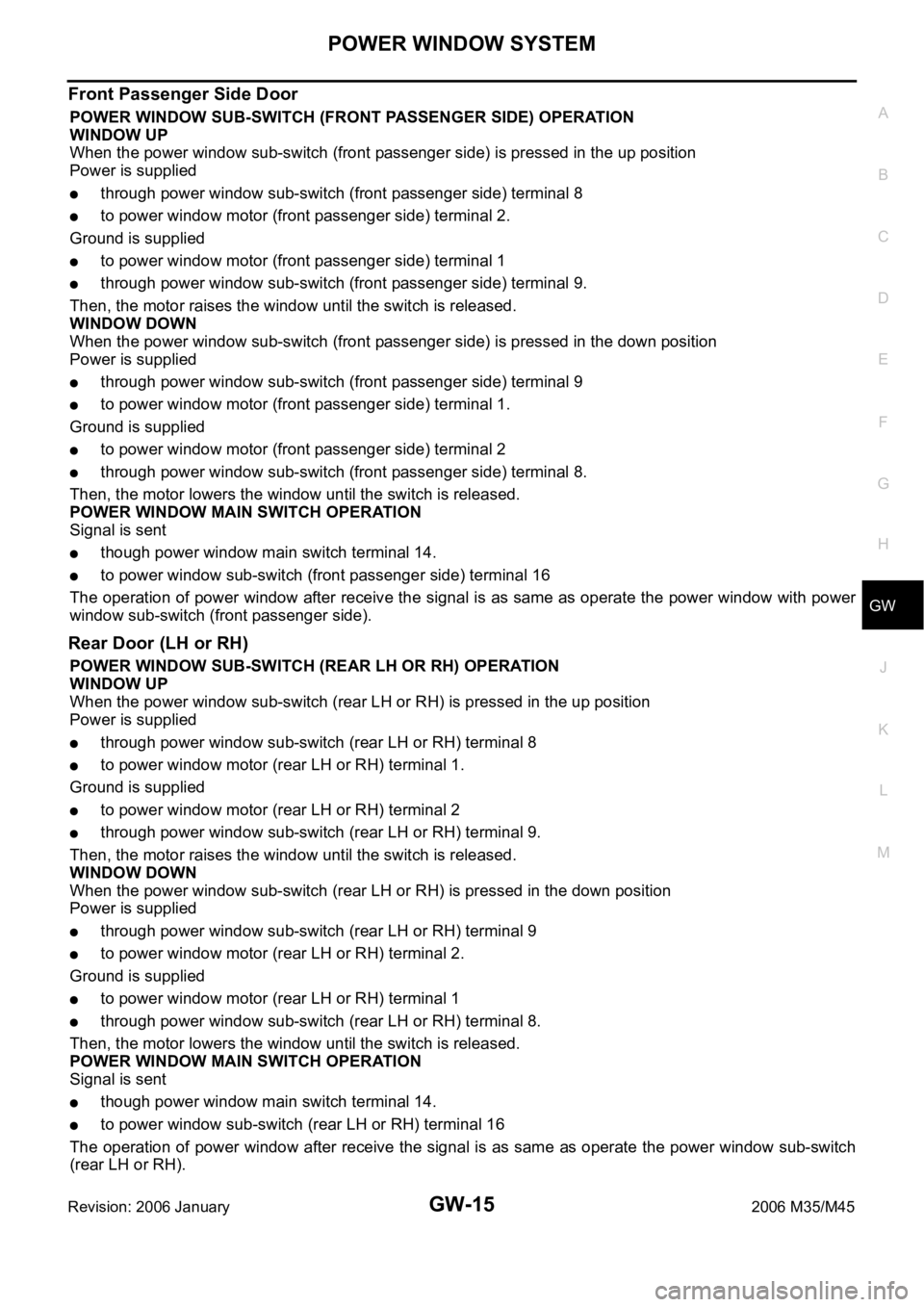
Front Passenger Side Door
POWER WINDOW SUB-SWITCH (FRONT PASSENGER SIDE) OPERATION
WINDOW UP
When the power window sub-switch (front passenger side) is pressed in the up position
Power is supplied
through power window sub-switch (front passenger side) terminal 8
to power window motor (front passenger side) terminal 2.
Ground is supplied
to power window motor (front passenger side) terminal 1
through power window sub-switch (front passenger side) terminal 9.
Then, the motor raises the window until the switch is released.
WINDOW DOWN
When the power window sub-switch (front passenger side) is pressed in the down position
Power is supplied
through power window sub-switch (front passenger side) terminal 9
to power window motor (front passenger side) terminal 1.
Ground is supplied
to power window motor (front passenger side) terminal 2
through power window sub-switch (front passenger side) terminal 8.
Then, the motor lowers the window until the switch is released.
POWER WINDOW MAIN SWITCH OPERATION
Signal is sent
though power window main switch terminal 14.
to power window sub-switch (front passenger side) terminal 16
The operation of power window after receive the signal is as same as operate the power window with power
window sub-switch (front passenger side).
Rear Door (LH or RH)
POWER WINDOW SUB-SWITCH (REAR LH OR RH) OPERATION
WINDOW UP
When the power window sub-switch (rear LH or RH) is pressed in the up position
Power is supplied
through power window sub-switch (rear LH or RH) terminal 8
to power window motor (rear LH or RH) terminal 1.
Ground is supplied
to power window motor (rear LH or RH) terminal 2
through power window sub-switch (rear LH or RH) terminal 9.
Then, the motor raises the window until the switch is released.
WINDOW DOWN
When the power window sub-switch (rear LH or RH) is pressed in the down position
Power is supplied
through power window sub-switch (rear LH or RH) terminal 9
to power window motor (rear LH or RH) terminal 2.
Ground is supplied
to power window motor (rear LH or RH) terminal 1
through power window sub-switch (rear LH or RH) terminal 8.
Then, the motor lowers the window until the switch is released.
POWER WINDOW MAIN SWITCH OPERATION
Signal is sent
though power window main switch terminal 14.
to power window sub-switch (rear LH or RH) terminal 16
The operation of power window after receive the signal is as same as operate the power window sub-switch
(rear LH or RH).