2006 INFINITI M35 stall
[x] Cancel search: stallPage 3407 of 5621
FFD-30
FRONT FINAL DRIVE ASSEMBLY
Revision: 2006 January2006 M35/M45
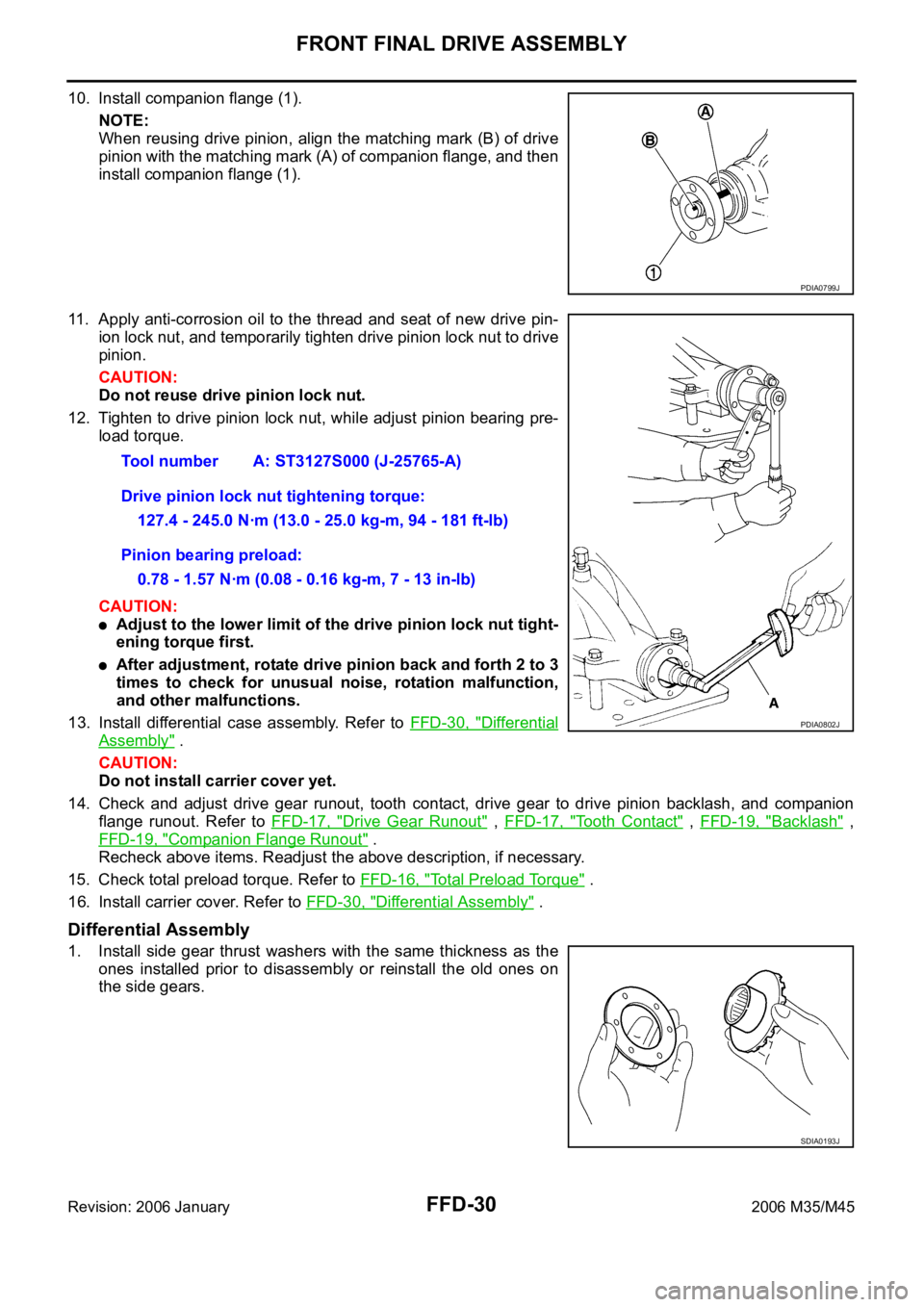
10. Install companion flange (1).
NOTE:
When reusing drive pinion, align the matching mark (B) of drive
pinion with the matching mark (A) of companion flange, and then
install companion flange (1).
11. Apply anti-corrosion oil to the thread and seat of new drive pin-
ion lock nut, and temporarily tighten drive pinion lock nut to drive
pinion.
CAUTION:
Do not reuse drive pinion lock nut.
12. Tighten to drive pinion lock nut, while adjust pinion bearing pre-
load torque.
CAUTION:
Adjust to the lower limit of the drive pinion lock nut tight-
ening torque first.
After adjustment, rotate drive pinion back and forth 2 to 3
times to check for unusual noise, rotation malfunction,
and other malfunctions.
13. Install differential case assembly. Refer to FFD-30, "
Differential
Assembly" .
CAUTION:
Do not install carrier cover yet.
14. Check and adjust drive gear runout, tooth contact, drive gear to drive pinion backlash, and companion
flange runout. Refer to FFD-17, "
Drive Gear Runout" , FFD-17, "Tooth Contact" , FFD-19, "Backlash" ,
FFD-19, "
Companion Flange Runout" .
Recheck above items. Readjust the above description, if necessary.
15. Check total preload torque. Refer to FFD-16, "
Total Preload Torque" .
16. Install carrier cover. Refer to FFD-30, "
Differential Assembly" .
Differential Assembly
1. Install side gear thrust washers with the same thickness as the
ones installed prior to disassembly or reinstall the old ones on
the side gears.
PDIA0799J
Tool number A: ST3127S000 (J-25765-A)
Drive pinion lock nut tightening torque:
127.4 - 245.0 Nꞏm (13.0 - 25.0 kg-m, 94 - 181 ft-lb)
Pinion bearing preload:
0.78 - 1.57 Nꞏm (0.08 - 0.16 kg-m, 7 - 13 in-lb)
PDIA0802J
SDIA0193J
Page 3408 of 5621
FRONT FINAL DRIVE ASSEMBLY
FFD-31
C
E
F
G
H
I
J
K
L
MA
B
FFD
Revision: 2006 January2006 M35/M45
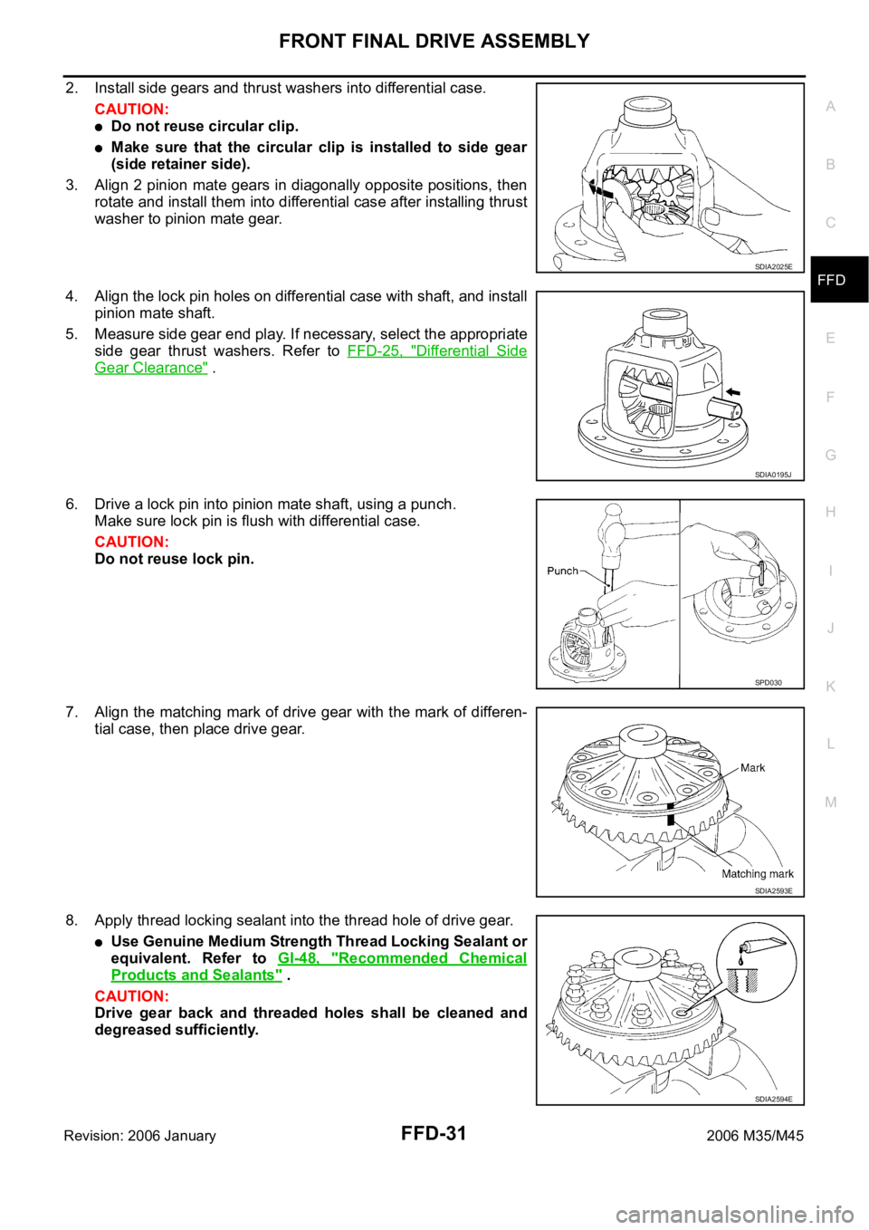
2. Install side gears and thrust washers into differential case.
CAUTION:
Do not reuse circular clip.
Make sure that the circular clip is installed to side gear
(side retainer side).
3. Align 2 pinion mate gears in diagonally opposite positions, then
rotate and install them into differential case after installing thrust
washer to pinion mate gear.
4. Align the lock pin holes on differential case with shaft, and install
pinion mate shaft.
5. Measure side gear end play. If necessary, select the appropriate
side gear thrust washers. Refer to FFD-25, "
Differential Side
Gear Clearance" .
6. Drive a lock pin into pinion mate shaft, using a punch.
Make sure lock pin is flush with differential case.
CAUTION:
Do not reuse lock pin.
7. Align the matching mark of drive gear with the mark of differen-
tial case, then place drive gear.
8. Apply thread locking sealant into the thread hole of drive gear.
Use Genuine Medium Strength Thread Locking Sealant or
equivalent. Refer to GI-48, "
Recommended Chemical
Products and Sealants" .
CAUTION:
Drive gear back and threaded holes shall be cleaned and
degreased sufficiently.
SDIA2025E
SDIA0195J
SPD030
SDIA2593E
SDIA2594E
Page 3409 of 5621
FFD-32
FRONT FINAL DRIVE ASSEMBLY
Revision: 2006 January2006 M35/M45
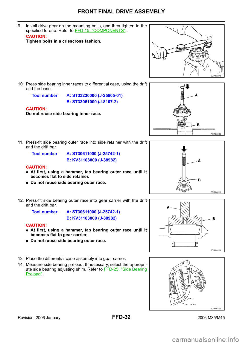
9. Install drive gear on the mounting bolts, and then tighten to the
specified torque. Refer to FFD-15, "
COMPONENTS" .
CAUTION:
Tighten bolts in a crisscross fashion.
10. Press side bearing inner races to differential case, using the drift
and the base.
CAUTION:
Do not reuse side bearing inner race.
11. Press-fit side bearing outer race into side retainer with the drift
and the drift bar.
CAUTION:
At first, using a hammer, tap bearing outer race until it
becomes flat to side retainer.
Do not reuse side bearing outer race.
12. Press-fit side bearing outer race into gear carrier with the drift
and the drift bar.
CAUTION:
At first, using a hammer, tap bearing outer race until it
becomes flat to gear carrier.
Do not reuse side bearing outer race.
13. Place the differential case assembly into gear carrier.
14. Measure side bearing preload. If necessary, select the appropri-
ate side bearing adjusting shim. Refer to FFD-25, "
Side Bearing
Preload" .
SDIA0247J
Tool number A: ST33230000 (J-25805-01)
B: ST33061000 (J-8107-2)
PDIA0810J
Tool number A: ST30611000 (J-25742-1)
B: KV31103000 (J-38982)
PDIA0811J
Tool number A: ST30611000 (J-25742-1)
B: KV31103000 (J-38982)
PDIA0812J
PDIA0671E
Page 3410 of 5621
FRONT FINAL DRIVE ASSEMBLY
FFD-33
C
E
F
G
H
I
J
K
L
MA
B
FFD
Revision: 2006 January2006 M35/M45
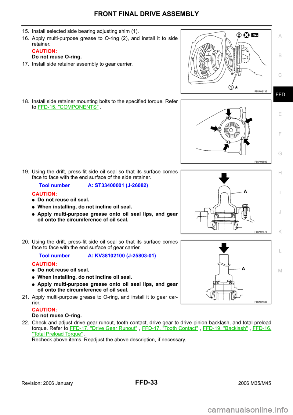
15. Install selected side bearing adjusting shim (1).
16. Apply multi-purpose grease to O-ring (2), and install it to side
retainer.
CAUTION:
Do not reuse O-ring.
17. Install side retainer assembly to gear carrier.
18. Install side retainer mounting bolts to the specified torque. Refer
to FFD-15, "
COMPONENTS" .
19. Using the drift, press-fit side oil seal so that its surface comes
face to face with the end surface of the side retainer.
CAUTION:
Do not reuse oil seal.
When installing, do not incline oil seal.
Apply multi-purpose grease onto oil seal lips, and gear
oil onto the circumference of oil seal.
20. Using the drift, press-fit side oil seal so that its surface comes
face to face with the end surface of gear carrier.
CAUTION:
Do not reuse oil seal.
When installing, do not incline oil seal.
Apply multi-purpose grease onto oil seal lips, and gear
oil onto the circumference of oil seal.
21. Apply multi-purpose grease to O-ring, and install it to gear car-
rier.
CAUTION:
Do not reuse O-ring.
22. Check and adjust drive gear runout, tooth contact, drive gear to drive pinion backlash, and total preload
torque. Refer to FFD-17, "
Drive Gear Runout" , FFD-17, "Tooth Contact" , FFD-19, "Backlash" , FFD-16,
"Total Preload Torque" .
Recheck above items. Readjust the above description, if necessary.
PDIA0813E
PDIA0669E
Tool number A: ST33400001 (J-26082)
PDIA0787J
Tool number A: KV38102100 (J-25803-01)
PDIA0788J
Page 3411 of 5621
FFD-34
FRONT FINAL DRIVE ASSEMBLY
Revision: 2006 January2006 M35/M45
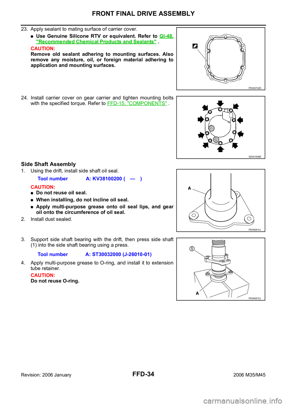
23. Apply sealant to mating surface of carrier cover.
Use Genuine Silicone RTV or equivalent. Refer to GI-48,
"Recommended Chemical Products and Sealants" .
CAUTION:
Remove old sealant adhering to mounting surfaces. Also
remove any moisture, oil, or foreign material adhering to
application and mounting surfaces.
24. Install carrier cover on gear carrier and tighten mounting bolts
with the specified torque. Refer to FFD-15, "
COMPONENTS" .
Side Shaft Assembly
1. Using the drift, install side shaft oil seal.
CAUTION:
Do not reuse oil seal.
When installing, do not incline oil seal.
Apply multi-purpose grease onto oil seal lips, and gear
oil onto the circumference of oil seal.
2. Install dust sealed.
3. Support side shaft bearing with the drift, then press side shaft
(1) into the side shaft bearing using a press.
4. Apply multi-purpose grease to O-ring, and install it to extension
tube retainer.
CAUTION:
Do not reuse O-ring.
PDIA0742E
SDIA1648E
Tool number A: KV38100200 ( — )
PDIA0814J
Tool number A: ST30032000 (J-26010-01)
PDIA0815J
Page 3414 of 5621
FL-1
FUEL SYSTEM
B ENGINE
CONTENTS
C
D
E
F
G
H
I
J
K
L
M
SECTION FL
A
FL
Revision: 2006 January2006 M35/M45
FUEL SYSTEM
PREPARATION ........................................................... 2
Commercial Service Tools ........................................ 2
FUEL SYSTEM ........................................................... 3
Checking Fuel Lines ............................................ ..... 3
General Precautions ................................................ 3
FUEL LEVEL SENSOR UNIT, FUEL FILTER AND
FUEL PUMP ASSEMBLY ........................................... 4
Components ............................................................. 4
Removal and Installation .......................................... 4
REMOVAL ........................................................
..... 4
INSTALLATION ..................................................... 6
INSPECTION AFTER INSTALLATION ................. 7Components ............................................................. 8
Disassembly and Assembly ...................................... 8
DISASSEMBLY ..................................................... 8
ASSEMBLY ........................................................... 9
FUEL TANK .............................................................. 10
Components ........................................................... 10
Removal and Installation ........................................ 10
REMOVAL ........................................................
... 10
INSTALLATION ................................................... 11
INSPECTION AFTER INSTALLATION ................ 11
SERVICE DATA AND SPECIFICATIONS (SDS) ...... 13
Standard and Limit .................................................. 13
FUEL TANK ...................................................... ... 13
Page 3416 of 5621
FUEL SYSTEM
FL-3
C
D
E
F
G
H
I
J
K
L
MA
FL
Revision: 2006 January2006 M35/M45
FUEL SYSTEMPFP:17503
Checking Fuel LinesNBS005R8
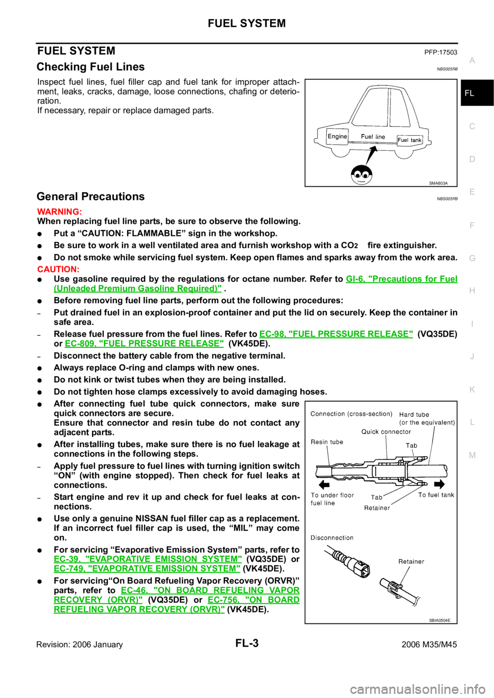
Inspect fuel lines, fuel filler cap and fuel tank for improper attach-
ment, leaks, cracks, damage, loose connections, chafing or deterio-
ration.
If necessary, repair or replace damaged parts.
General PrecautionsNBS005R9
WAR NING :
When replacing fuel line parts, be sure to observe the following.
Put a “CAUTION: FLAMMABLE” sign in the workshop.
Be sure to work in a well ventilated area and furnish workshop with a CO2 fire extinguisher.
Do not smoke while servicing fuel system. Keep open flames and sparks away from the work area.
CAUTION:
Use gasoline required by the regulations for octane number. Refer to GI-6, "Precautions for Fuel
(Unleaded Premium Gasoline Required)" .
Before removing fuel line parts, perform out the following procedures:
–Put drained fuel in an explosion-proof container and put the lid on securely. Keep the container in
safe area.
–Release fuel pressure from the fuel lines. Refer to EC-98, "FUEL PRESSURE RELEASE" (VQ35DE)
or EC-809, "
FUEL PRESSURE RELEASE" (VK45DE).
–Disconnect the battery cable from the negative terminal.
Always replace O-ring and clamps with new ones.
Do not kink or twist tubes when they are being installed.
Do not tighten hose clamps excessively to avoid damaging hoses.
After connecting fuel tube quick connectors, make sure
quick connectors are secure.
Ensure that connector and resin tube do not contact any
adjacent parts.
After installing tubes, make sure there is no fuel leakage at
connections in the following steps.
–Apply fuel pressure to fuel lines with turning ignition switch
“ON” (with engine stopped). Then check for fuel leaks at
connections.
–Start engine and rev it up and check for fuel leaks at con-
nections.
Use only a genuine NISSAN fuel filler cap as a replacement.
If an incorrect fuel filler cap is used, the “MIL” may come
on.
For servicing “Evaporative Emission System” parts, refer to
EC-39, "
EVAPORATIVE EMISSION SYSTEM" (VQ35DE) or
EC-749, "
EVAPORATIVE EMISSION SYSTEM" (VK45DE).
For servicing“On Board Refueling Vapor Recovery (ORVR)”
parts, refer to EC-46, "
ON BOARD REFUELING VAPOR
RECOVERY (ORVR)" (VQ35DE) or EC-756, "ON BOARD
REFUELING VAPOR RECOVERY (ORVR)" (VK45DE).
SMA803A
SBIA0504E
Page 3417 of 5621
FL-4
FUEL LEVEL SENSOR UNIT, FUEL FILTER AND FUEL PUMP ASSEMBLY
Revision: 2006 January2006 M35/M45
FUEL LEVEL SENSOR UNIT, FUEL FILTER AND FUEL PUMP ASSEMBLYPFP:17042
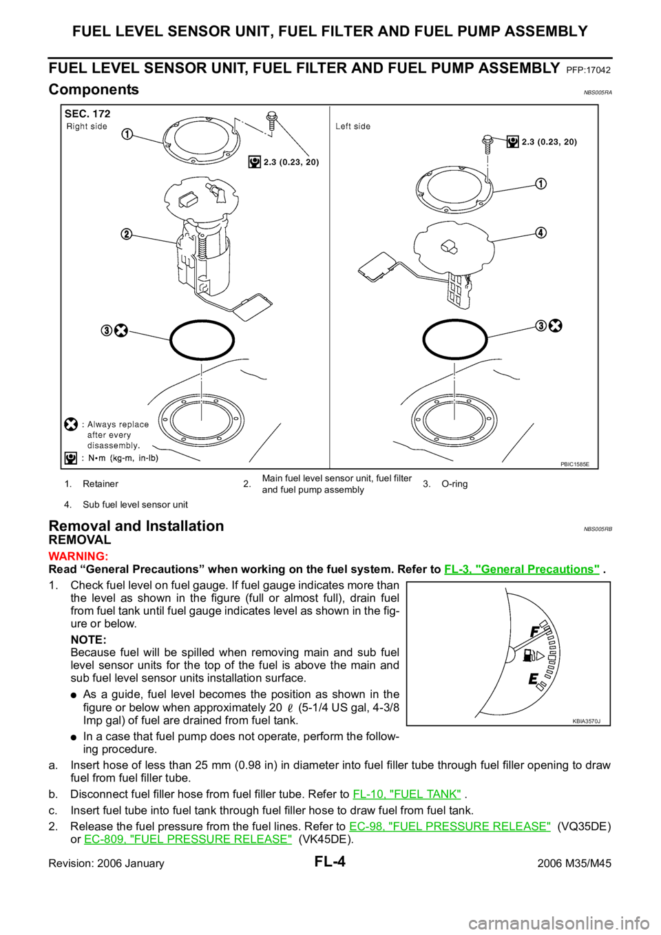
ComponentsNBS005RA
Removal and InstallationNBS005RB
REMOVAL
WAR NING :
Read “General Precautions” when working on the fuel system. Refer to FL-3, "
General Precautions" .
1. Check fuel level on fuel gauge. If fuel gauge indicates more than
the level as shown in the figure (full or almost full), drain fuel
from fuel tank until fuel gauge indicates level as shown in the fig-
ure or below.
NOTE:
Because fuel will be spilled when removing main and sub fuel
level sensor units for the top of the fuel is above the main and
sub fuel level sensor units installation surface.
As a guide, fuel level becomes the position as shown in the
figure or below when approximately 20 (5-1/4 US gal, 4-3/8
Imp gal) of fuel are drained from fuel tank.
In a case that fuel pump does not operate, perform the follow-
ing procedure.
a. Insert hose of less than 25 mm (0.98 in) in diameter into fuel filler tube through fuel filler opening to draw
fuel from fuel filler tube.
b. Disconnect fuel filler hose from fuel filler tube. Refer to FL-10, "
FUEL TANK" .
c. Insert fuel tube into fuel tank through fuel filler hose to draw fuel from fuel tank.
2. Release the fuel pressure from the fuel lines. Refer to EC-98, "
FUEL PRESSURE RELEASE" (VQ35DE)
or EC-809, "
FUEL PRESSURE RELEASE" (VK45DE).
1. Retainer 2.Main fuel level sensor unit, fuel filter
and fuel pump assembly3. O-ring
4. Sub fuel level sensor unit
PBIC1585E
KBIA3570J