Page 3354 of 4462
IP-12
INSTRUMENT PANEL ASSEMBLY
Revision: 2006 December 2006 FX35/FX45
REMOVAL
(A) Front Kicking Plate (RH/LH)
Remove front kicking plate (RH/LH). Refer to EI-37, "BODY SIDE TRIM" .
(B) Dash Side Finisher (RH/LH)
1. Remove plastics nut.
2. Remove dash side finisher (RH/LH). Refer to EI-37, "
BODY SIDE TRIM" .
(C) Front Pillar Garnish (RH/LH)
Pull to inside of vehicle, disengage metal clips and remove front pillar garnish. Refer to EI-37, "BODY SIDE
TRIM" .
(D) A/T Select Lever Knob
1. Pull down knob cover.
2. Remove lock-pin of select lever knob.
3. Lift up select lever knob and remove select lever knob. Refer to AT- 2 2 9 , "
Control Device Removal and
Installation" .
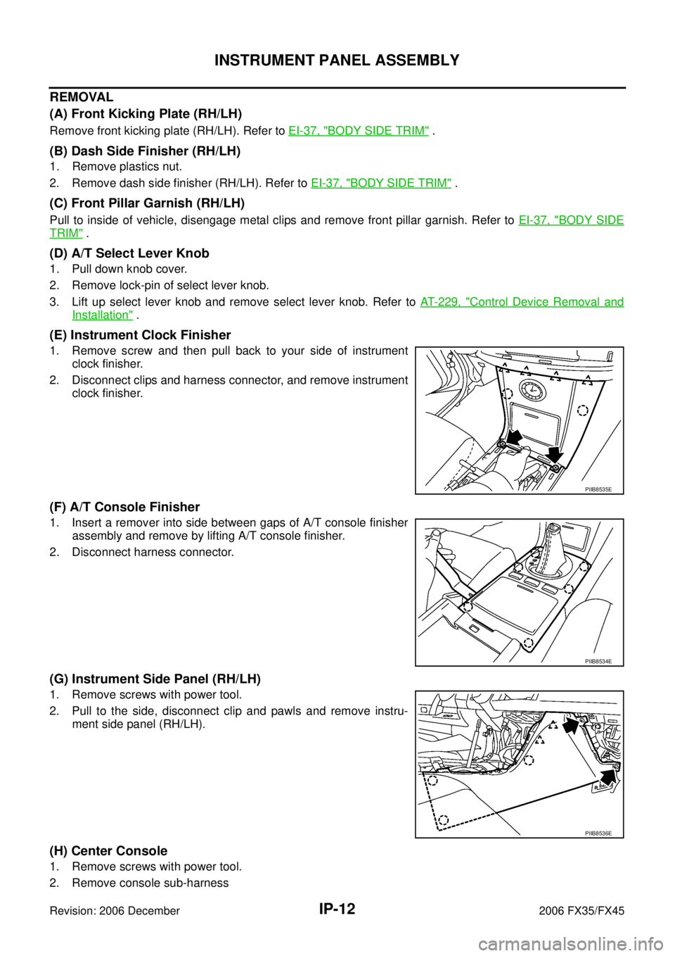
(E) Instrument Clock Finisher
1. Remove screw and then pull back to your side of instrument
clock finisher.
2. Disconnect clips and harness connector, and remove instrument clock finisher.
(F) A/T Console Finisher
1. Insert a remover into side between gaps of A/T console finisher assembly and remove by lifting A/T console finisher.
2. Disconnect harness connector.
(G) Instrument Side Panel (RH/LH)
1. Remove screws with power tool.
2. Pull to the side, disconnect clip and pawls and remove instru- ment side panel (RH/LH).
(H) Center Console
1. Remove screws with power tool.
2. Remove console sub-harness
PIIB8535E
PIIB8534E
PIIB8536E
Page 3358 of 4462
IP-16
INSTRUMENT PANEL ASSEMBLY
Revision: 2006 December 2006 FX35/FX45
Disassembly and AssemblyNIS001UG
A/T CONSOLE FINISHER
Disassembly
1. Remove screws with power tool and remove instrument ashtray.
2. Remove screws with power tool and remove instrument clock panel.
3. Remove screws with power tool of back side and remove cup holder.
4. Remove screws of back side and remove position indicator plate.
Assembly
Assemble in the reverse order of disassembly.
1. Instrument clock panel 2. Instrument clock finisher 3. Ashtry
4. Cup holder 5. Cup holder inner 6. A/T console finisher
7. A/T console panel
PIIB8537E
Page 3597 of 4462
HEADLAMP - XENON TYPE - LT-35
C
D E
F
G H
I
J
L
M A
B
LT
Revision: 2006 December 2006 FX35/FX45
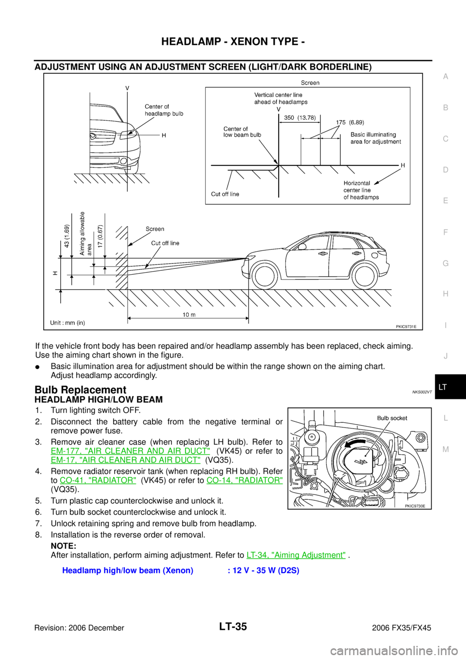
ADJUSTMENT USING AN ADJUSTMENT SCREEN (LIGHT/DARK BORDERLINE)
If the vehicle front body has been repaired and/or headlamp assembly has been replaced, check aiming.
Use the aiming chart shown in the figure.
�Basic illumination area for adjustment should be within the range shown on the aiming chart.
Adjust headlamp accordingly.
Bulb ReplacementNKS002VT
HEADLAMP HIGH/LOW BEAM
1. Turn lighting switch OFF.
2. Disconnect the battery cable from the negative terminal or remove power fuse.
3. Remove air cleaner case (when replacing LH bulb). Refer to EM-177, "
AIR CLEANER AND AIR DUCT" (VK45) or refer to
EM-17, "
AIR CLEANER AND AIR DUCT" (VQ35).
4. Remove radiator reservoir tank (when replacing RH bulb). Refer to CO-41, "
RADIATOR" (VK45) or refer to CO-14, "RADIATOR"
(VQ35).
5. Turn plastic cap counterclockwise and unlock it.
6. Turn bulb socket counterclockwise and unlock it.
7. Unlock retaining spring and remove bulb from headlamp.
8. Installation is the reverse order of removal.
NOTE:
After installation, perform aiming adjustment. Refer to LT- 3 4 , "
Aiming Adjustment" .
PKIC9731E
Headlamp high/low beam (Xenon) : 12 V - 35 W (D2S)
PKIC9730E
Page 3598 of 4462
LT-36
HEADLAMP - XENON TYPE -
Revision: 2006 December 2006 FX35/FX45
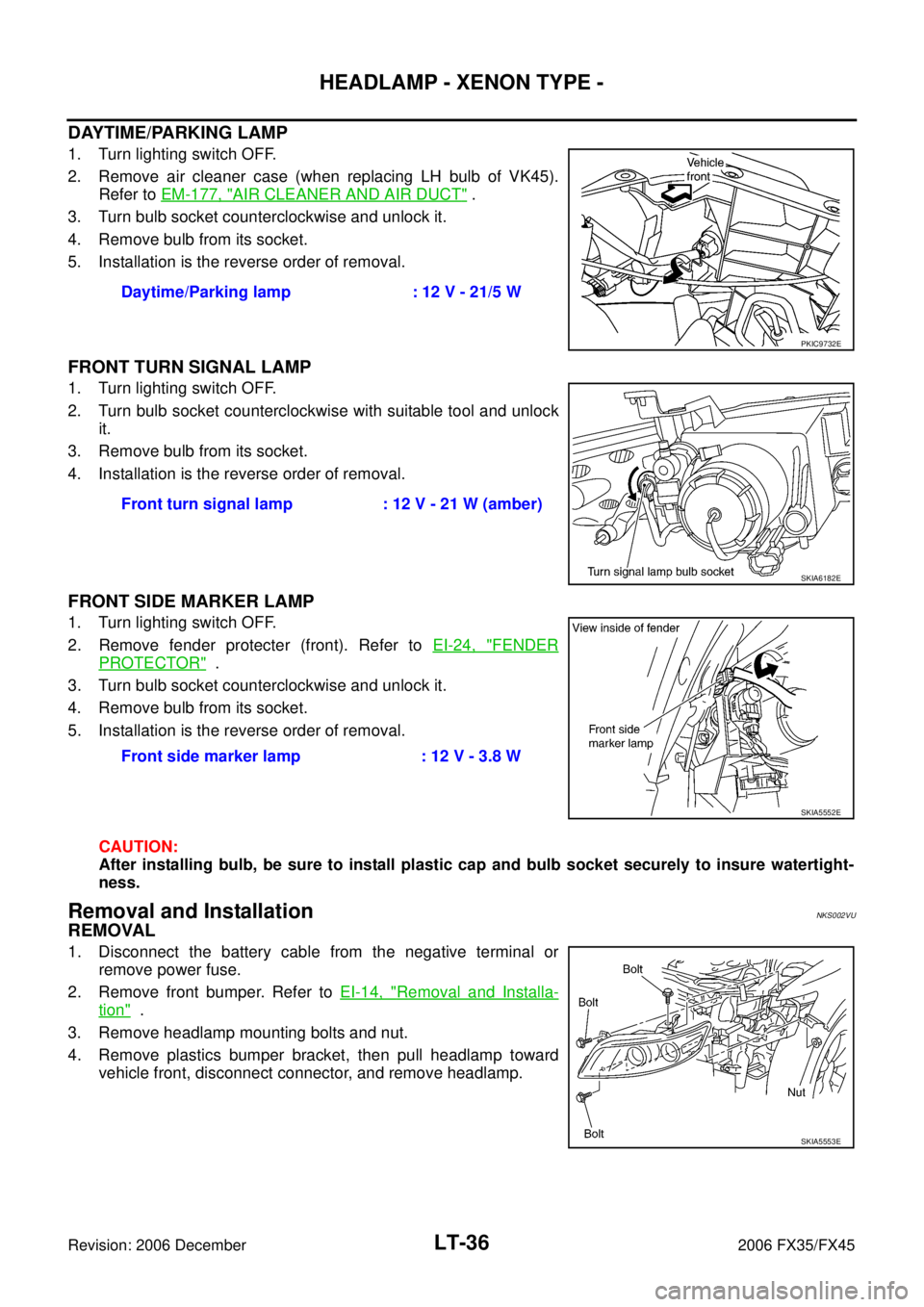
DAYTIME/PARKING LAMP
1. Turn lighting switch OFF.
2. Remove air cleaner case (when replacing LH bulb of VK45). Refer to EM-177, "
AIR CLEANER AND AIR DUCT" .
3. Turn bulb socket counterclockwise and unlock it.
4. Remove bulb from its socket.
5. Installation is the reverse order of removal.
FRONT TURN SIGNAL LAMP
1. Turn lighting switch OFF.
2. Turn bulb socket counterclockwise with suitable tool and unlock it.
3. Remove bulb from its socket.
4. Installation is the reverse order of removal.
FRONT SIDE MARKER LAMP
1. Turn lighting switch OFF.
2. Remove fender protecter (front). Refer to EI-24, "
FENDER
PROTECTOR" .
3. Turn bulb socket counterclockwise and unlock it.
4. Remove bulb from its socket.
5. Installation is the reverse order of removal.
CAUTION:
After installing bulb, be sure to install plastic cap and bulb socket securely to insure watertight-
ness.
Removal and InstallationNKS002VU
REMOVAL
1. Disconnect the battery cable from the negative terminal or remove power fuse.
2. Remove front bumper. Refer to EI-14, "
Removal and Installa-
tion" .
3. Remove headlamp mounting bolts and nut.
4. Remove plastics bumper bracket, then pull headlamp toward vehicle front, disconnect connector, and remove headlamp. Daytime/Parking lamp : 12 V - 21/5 W
PKIC9732E
Front turn signal lamp : 12 V - 21 W (amber)
SKIA6182E
Front side marker lamp : 12 V - 3.8 W
SKIA5552E
SKIA5553E
Page 3599 of 4462
HEADLAMP - XENON TYPE - LT-37
C
D E
F
G H
I
J
L
M A
B
LT
Revision: 2006 December 2006 FX35/FX45
INSTALLATION
Installation is the reverse order of removal.
NOTE:
After installation, perform aiming adjustment. Refer to LT- 3 4 , "
Aiming Adjustment" .
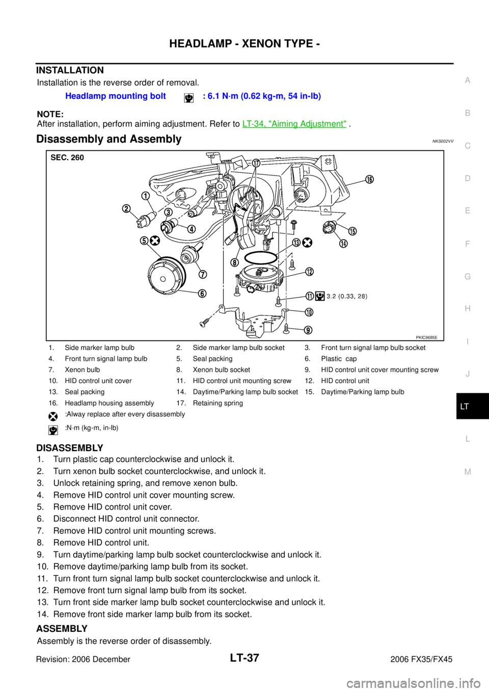
Disassembly and Assembly NKS002VV
DISASSEMBLY
1. Turn plastic cap counterclockwise and unlock it.
2. Turn xenon bulb socket counterclockwise, and unlock it.
3. Unlock retaining spring, and remove xenon bulb.
4. Remove HID control unit cover mounting screw.
5. Remove HID control unit cover.
6. Disconnect HID control unit connector.
7. Remove HID control unit mounting screws.
8. Remove HID control unit.
9. Turn daytime/parking lamp bulb socket counterclockwise and unlock it.
10. Remove daytime/parking lamp bulb from its socket.
11. Turn front turn signal lamp bulb socket counterclockwise and unlock it.
12. Remove front turn signal lamp bulb from its socket.
13. Turn front side marker lamp bulb socket counterclockwise and unlock it.
14. Remove front side marker lamp bulb from its socket.
ASSEMBLY
Assembly is the reverse order of disassembly. Headlamp mounting bolt : 6.1 N·m (0.62 kg-m, 54 in-lb)
1. Side marker lamp bulb 2. Side marker lamp bulb socket 3. Front turn signal lamp bulb socket
4. Front turn signal lamp bulb 5. Seal packing 6. Plastic cap
7. Xenon bulb 8. Xenon bulb socket 9. HID control unit cover mounting screw
10. HID control unit cover 11. HID control unit mounting screw 12. HID control unit
13. Seal packing 14. Daytime/Parking lamp bulb socket 15. Daytime/Parking lamp bulb
16. Headlamp housing assembly 17. Retaining spring :Alway replace after every disassembly
:N·m (kg-m, in-lb)
PKIC9685E
Page 3651 of 4462
FRONT FOG LAMP LT-89
C
D E
F
G H
I
J
L
M A
B
LT
Revision: 2006 December 2006 FX35/FX45
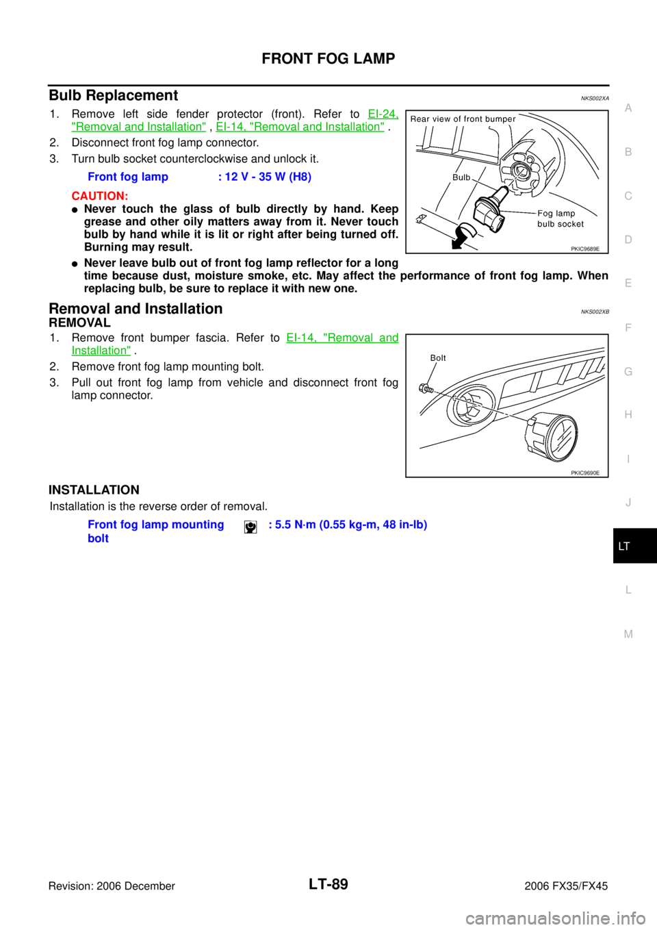
Bulb Replacement NKS002XA
1. Remove left side fender protector (front). Refer to EI-24,
"Removal and Installation" , EI-14, "Removal and Installation" .
2. Disconnect front fog lamp connector.
3. Turn bulb socket counterclockwise and unlock it.
CAUTION:
�Never touch the glass of bulb directly by hand. Keep
grease and other oily matters away from it. Never touch
bulb by hand while it is lit or right after being turned off.
Burning may result.
�Never leave bulb out of front fog lamp reflector for a long
time because dust, moisture smoke, etc. May affect the performance of front fog lamp. When
replacing bulb, be sure to replace it with new one.
Removal and Installation NKS002XB
REMOVAL
1. Remove front bumper fascia. Refer to EI-14, "Removal and
Installation" .
2. Remove front fog lamp mounting bolt.
3. Pull out front fog lamp from vehicle and disconnect front fog lamp connector.
INSTALLATION
Installation is the reverse order of removal. Front fog lamp : 12 V - 35 W (H8)
PKIC9689E
PKIC9690E
Front fog lamp mounting
bolt : 5.5 N·m (0.55 kg-m, 48 in-lb)
Page 3716 of 4462
LT-154
REAR COMBINATION LAMP
Revision: 2006 December 2006 FX35/FX45
REAR COMBINATION LAMPPFP:26554
Bulb ReplacementNKS003HK
REAR FENDER SIDE (REAR SIDE MARKER LAMP BULB)
1. Remove rear combination lamp.
2. Turn bulb socket counterclockwise and unlock it.
3. Remove bulb.
BACK DOOR SIDE (BACK-UP LAMP)
1. Remove rear combination lamp.
2. Turn bulb socket counterclockwise and unlock it.
3. Remove bulb.
Removal and InstallationNKS003HL
REMOVAL
Rear Fender Side
1. Remove bumper side cover A. Refer to EI-17, "Removal and
Installation" .
2. Disconnect rear combination lamp connector.
3. Remove rear combination lamp mounting bolts.
4. Pull rear combination lamp toward side of the vehicle and remove from the vehicle.
SKIA5569E
PKIB3634E
Stop/tail lamp and rear turn signal lamp
(rear fender side) : LED (Replace together with rear combination
lamp assembly.)
Rear side marker lamp (rear fender side) : 12 V - 3.8 W
Back-up lamp (back door side) : 12 V - 18 W
SKIA5571E
Page 3747 of 4462
INTERIOR ROOM LAMP LT-185
C
D E
F
G H
I
J
L
M A
B
LT
Revision: 2006 December 2006 FX35/FX45
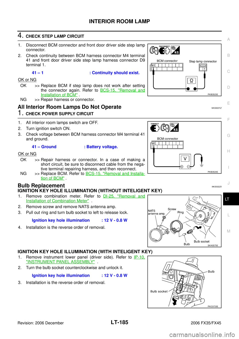
4. CHECK STEP LAMP CIRCUIT
1. Disconnect BCM connector and front door driver side step lamp connector.
2. Check continuity between BCM harness connector M4 terminal 41 and front door driver side step lamp harness connector D9
terminal 1.
OK or NG
OK >> Replace BCM if step lamp does not work after setting the connector again. Refer to BCS-15, "
Removal and
Installation of BCM" .
NG >> Repair harness or connector.
All Interior Room Lamps Do Not OperateNKS002YZ
1. CHECK POWER SUPPLY CIRCUIT
1. All interior room lamps switch are OFF.
2. Turn ignition switch ON.
3. Check voltage between BCM harness connector M4 terminal 41 and ground.
OK or NG
OK >> Repair harness or connector. In a case of making a short circuit, be sure to disconnect cable from the nega-
tive terminal repairing harness, and then reconnect.
NG >> Replace BCM. Refer to BCS-15, "
Removal and Installa-
tion of BCM" .
Bulb ReplacementNKS002Z0
IGNITION KEY HOLE ILLUMINATION (WITHOUT INTELIGENT KEY)
1. Remove combination meter. Refer to DI-25, "Removal and
Installation of Combination Meter" .
2. Remove screw and remove NATS antenna amp.
3. Pull out ring and turn bulb socket to left to release lock.
4. Installation is the reverse order of removal.
IGNITION KEY HOLE ILLUMINATION (WITH INTELIGENT KEY)
1. Remove instrument lower panel (driver side). Refer to IP-10,
"INSTRUMENT PANEL ASSEMBLY" .
2. Turn the bulb socket counterclockwise and unlock it.
3. Installation is the reverse order of removal. 41 – 1 : Continuity should exist.
PKIB3523E
41 – Ground : Battery voltage.
PKIB3524E
Ignition key hole illumination : 12 V - 0.8 W
SKIA5575E
Ignition key hole illumination : 12 V - 0.8 W
PKIC9733E