SPIRAL CABLE SRS-41
C
D E
F
G
I
J
K L
M A
B
SRS
Revision: 2006 December 2006 FX35/FX45
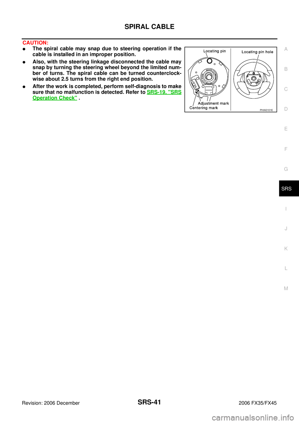
CAUTION:
�The spiral cable may snap due to steering operation if the
cable is installed in an improper position.
�Also, with the steering linkage disconnected the cable may
snap by turning the steering wheel beyond the limited num-
ber of turns. The spiral cable can be turned counterclock-
wise about 2.5 turns from the right end position.
�After the work is completed, perform self-diagnosis to make
sure that no malfunction is detected. Refer to SRS-19, "
SRS
Operation Check" .
PHIA0101E
WW-56
POWER SOCKET
Revision: 2006 December 2006 FX35/FX45
Removal and Installation of Front Power Socket – 1NKS003N8
REMOVAL
1. Remove A/T console finisher. Refer to IP-10, "INSTRUMENT
PANEL ASSEMBLY" .
2. Remove instrument clock finisher. Refer to IP-10, "
INSTRU-
MENT PANEL ASSEMBLY" .
3. Disconnect power socket connector.
4. Remove inner socket from the ring. While pressing the hook on the ring out from square hole.
5. Remove ring from ashtry while pressing pawls.
INSTALLATION
Installation is the reverse order of removal.
Removal and Installation of Front Power Socket – 2NKS0033U
REMOVAL
1. Remove inner socket from the ring. While pressing the hook on the ring out from square hole.
2. Remove ring from power socket finisher while pressing pawls.
3. Disconnect power socket connector.
INSTALLATION
Installation is the reverse order of removal.
Removal and Installation of Rear Power SocketNKS004F1
REMOVAL
1. Remove console rear finisher. Refer to IP-17, "CENTER CON-
SOLE" .
2. Disconnect power socket connector.
3. Remove inner socket from the ring. While pressing the hook on the ring out from square hole.
4. Remove ring from power socket finisher while pressing pawls.
INSTALLATION
Installation is the reverse order of removal.
PKIC9710E
SKIA5096E
SKIA5094E