Page 4291 of 4462
FRONT PASSENGER AIR BAG MODULE SRS-43
C
D E
F
G
I
J
K L
M A
B
SRS
Revision: 2006 December 2006 FX35/FX45
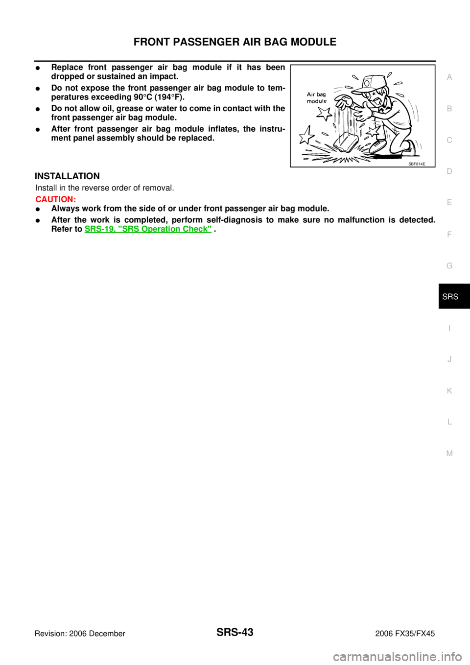
�Replace front passenger air bag module if it has been
dropped or sustained an impact.
�Do not expose the front passenger air bag module to tem-
peratures exceeding 90 °C (194 °F).
�Do not allow oil, grease or water to come in contact with the
front passenger air bag module.
�After front passenger air bag module inflates, the instru-
ment panel assembly should be replaced.
INSTALLATION
Install in the reverse order of removal.
CAUTION:
�Always work from the side of or under front passenger air bag module.
�After the work is completed, perform self-diagnosis to make sure no malfunction is detected.
Refer to SRS-19, "
SRS Operation Check" .
SBF814E
Page 4292 of 4462

SRS-44
SIDE CURTAIN AIR BAG MODULE
Revision: 2006 December 2006 FX35/FX45
SIDE CURTAIN AIR BAG MODULEPFP:985P0
Removal and InstallationNHS0007O
REMOVAL
CAUTION:
�Before servicing SRS, turn ignition switch OFF, disconnect both battery cables and wait at least 3
minutes.
�Always work from the side of the side curtain air bag module.
1. Remove headlining. Refer to EI-42, "
Removal and Installation" .
2. Disconnect side curtain air bag connector.
3. Remove side curtain air bag module fixing bolts, and remove the side curtain air bag module.
CAUTION:
�Always place the side curtain air bag module with the warn-
ing label facing upward.
�Do not disassemble side curtain air bag module.
�Do not insert any foreign objects (screwdriver, etc.) into air
bag module connector.
�Replace side curtain air bag module if it has been dropped
or sustained an impact.
�Do not expose the air bag module to temperatures exceed-
ing 90 °C (194 °F).
�Do not allow oil, grease or water to come in contact with the
side curtain air bag module.
1. Side curtain air bag Inflator 2. Side curtain air bag 3. Bolt
4. Assist grip bracket 5. Bolt (There is no torque control)
PHIA0656E
PHIA0317E
SBF814E
Page 4293 of 4462
SIDE CURTAIN AIR BAG MODULE SRS-45
C
D E
F
G
I
J
K L
M A
B
SRS
Revision: 2006 December 2006 FX35/FX45
INSTALLATION
Install in the reverse order of removal.
CAUTION:
�Always work from the side of the side curtain air bag module.
�After replacement of side curtain air bag module, perform self-diagnosis to make sure that no mal-
function is detected. Refer to SRS-19, "
SRS Operation Check" .
Page 4294 of 4462
SRS-46
CRASH ZONE SENSOR
Revision: 2006 December 2006 FX35/FX45
CRASH ZONE SENSORPFP:98531
Removal and InstallationNHS0007P
REMOVAL
CAUTION:
Before servicing SRS, turn ignition switch OFF, disconnect both battery cables and wait at least 3 min-
utes.
1. Remove front grille. Refer to EI-22, "
Removal and Installation" .
2. Remove crash zone sensor connector.
3. Remove crash zone sensor fixing nuts.
CAUTION:
�Replace crash zone sensor if it has been dropped or sustained an impact.
�Do not disassemble crash zone sensor.
INSTALLATION
Install in the reverse order of removal.
CAUTION:
�Check crash zone sensor for proper installation.
�After the work is complete, perform self-diagnosis to make sure that no malfunction is detected.
Refer to SRS-19, "
SRS Operation Check" .
PHIA0316E
Page 4295 of 4462
 SENSOR SRS-47
C
D E
F
G
I
J
K L
M A
B
SRS
Revision: 2006 December 2006 FX35/FX45
SIDE AIR BAG (SATELLITE) SENSORPFP:98830
Removal and InstallationNHS0007Q
REMOVAL")
SIDE AIR BAG (SATELLITE) SENSOR SRS-47
C
D E
F
G
I
J
K L
M A
B
SRS
Revision: 2006 December 2006 FX35/FX45
SIDE AIR BAG (SATELLITE) SENSORPFP:98830
Removal and InstallationNHS0007Q
REMOVAL
CAUTION:
Before servicing SRS, turn ignition switch OFF, disconnect both battery cables and wait at least 3 min-
utes.
1. Remove seat belt pre-tensioner. Refer to SB-4, "
Removal and Installation of Front Seat Belt" .
2. Remove side air bag (Satellite) sensor fixing nuts.
3. Remove the side air bag (Satellite) sensor connector.
CAUTION:
�Do not use old nuts; replace with new ones.
�Check side air bag (Satellite) sensor to ensure it is free of deformities, dents, cracks or rust. If it
shows any visible signs of damage, replace it with new one.
�Do not disassemble side air bag (Satellite) sensor.
�Replace side air bag (Satellite) sensor if it has been dropped or sustained an impact.
INSTALLATION
Install in the reverse order of removal.
CAUTION:
�Check side air bag (Satellite) sensor for proper installation.
�After replacement of side air bag (Satellite) sensor, perform self-diagnosis to make sure that no
malfunction is detected. Refer to SRS-19, "
SRS Operation Check" .
PHIA0314E
Page 4296 of 4462
SRS-48
FRONT SEAT BELT PRE-TENSIONER
Revision: 2006 December 2006 FX35/FX45
FRONT SEAT BELT PRE-TENSIONERPFP:86884
Removal and InstallationNHS0007R
For removal and installation procedures, refer to SB-4, "Removal and Installation of Front Seat Belt" .
Page 4297 of 4462

DIAGNOSIS SENSOR UNIT SRS-49
C
D E
F
G
I
J
K L
M A
B
SRS
Revision: 2006 December 2006 FX35/FX45
DIAGNOSIS SENSOR UNITPFP:28556
Removal and InstallationNHS0007S
REMOVAL
CAUTION:
Before servicing SRS, turn ignition switch OFF, disconnect both battery cables and wait at least 3 min-
utes.
1. Disconnect each harness connector for the air bag module and seat belt pre-tensioner.
2. Remove center console. Refer to IP-11, "
Removal and Installation" .
3. Disconnect diagnosis sensor unit connector.
4. Remove special bolts (T50) from the diagnosis sensor unit.
CAUTION:
�Do not use old bolts. Replace with new ones.
�Check diagnosis sensor unit bracket to ensure it is free of
deformities, dents, cracks or rust. If it shows any visible
things of damage, replace with new one.
�Replace diagnosis sensor unit if it has been dropped or
sustained an impact.
INSTALLATION
Install in the reverse order of removal.
CAUTION:
�Check the diagnosis sensor unit for proper installation.
�After replacement of diagnosis sensor unit, perform self-diagnosis to make sure that no malfunc-
tion is detected. Refer to SRS-19, "
SRS Operation Check" .
ECU DISCRIMINATED NO.
After replacing the diagnosis sensor unit, confirm that the diagnosis sensor unit identification is correct for the
vehicle as equipped.
PHIA0315E
Specification ECU DISCRIMINATED No.
Models with driver and passenger air bags, seat belt pre-tensioner, side air bags and curtain air bags FB04
Page 4304 of 4462

TF-2Revision: 2006 December 2006 FX35/FX45 Started .................................................................
... 35
DIAGNOSTIC PROCEDURE ........................... ... 35
Vehicle Does Not Enter AWD Mode Even Though
AWD Warning Lamp Turned to OFF .................... ... 36
DIAGNOSTIC PROCEDURE ........................... ... 36
While Driving, AWD Warning Lamp Flashes Rapidly
(When Flashing in Approx. 1 Minute and Then Turn-
ing OFF) .............................................................. ... 37
While Driving, AWD Warning Lamp Flashes Slowly
(When Continuing to Flash until Turning Ignition
Switch OFF) ......................................................... ... 37
DIAGNOSTIC PROCEDURE ........................... ... 37
AWD CONTROL UNIT ........................................... ... 39
Removal and Installation ..................................... ... 39
REMOVAL ........................................................ ... 39
INSTALLATION ................................................. ... 39
FRONT OIL SEAL .................................................. ... 40
Removal and Installation ..................................... ... 40
REMOVAL ........................................................ ... 40
INSTALLATION ................................................. ... 40 REAR OIL SEAL ....................................................
... 41
Removal and Installation ...................................... ... 41
REMOVAL ......................................................... ... 41
INSTALLATION ................................................. ... 42
AIR BREATHER HOSE .......................................... ... 43
Removal and Installation ...................................... ... 43
TRANSFER ASSEMBLY ........................................ ... 44
Removal and Installation ...................................... ... 44
REMOVAL ......................................................... ... 44
INSTALLATION ................................................. ... 44
Disassembly and Assembly ................................. ... 45
COMPONENTS ................................................ ... 45
DISASSEMBLY ................................................. ... 46
INSPECTION .................................................... ... 51
ASSEMBLY ....................................................... ... 52
SERVICE DATA AND SPECIFICATIONS (SDS) ... ... 59
General Specifications ......................................... ... 59