Page 798 of 4462
AV-192
TELEPHONE
Revision: 2006 December 2006 FX35/FX45
Page 1410 of 4462
EC-26
[VQ35DE]
PRECAUTIONS
Revision: 2006 December 2006 FX35/FX45
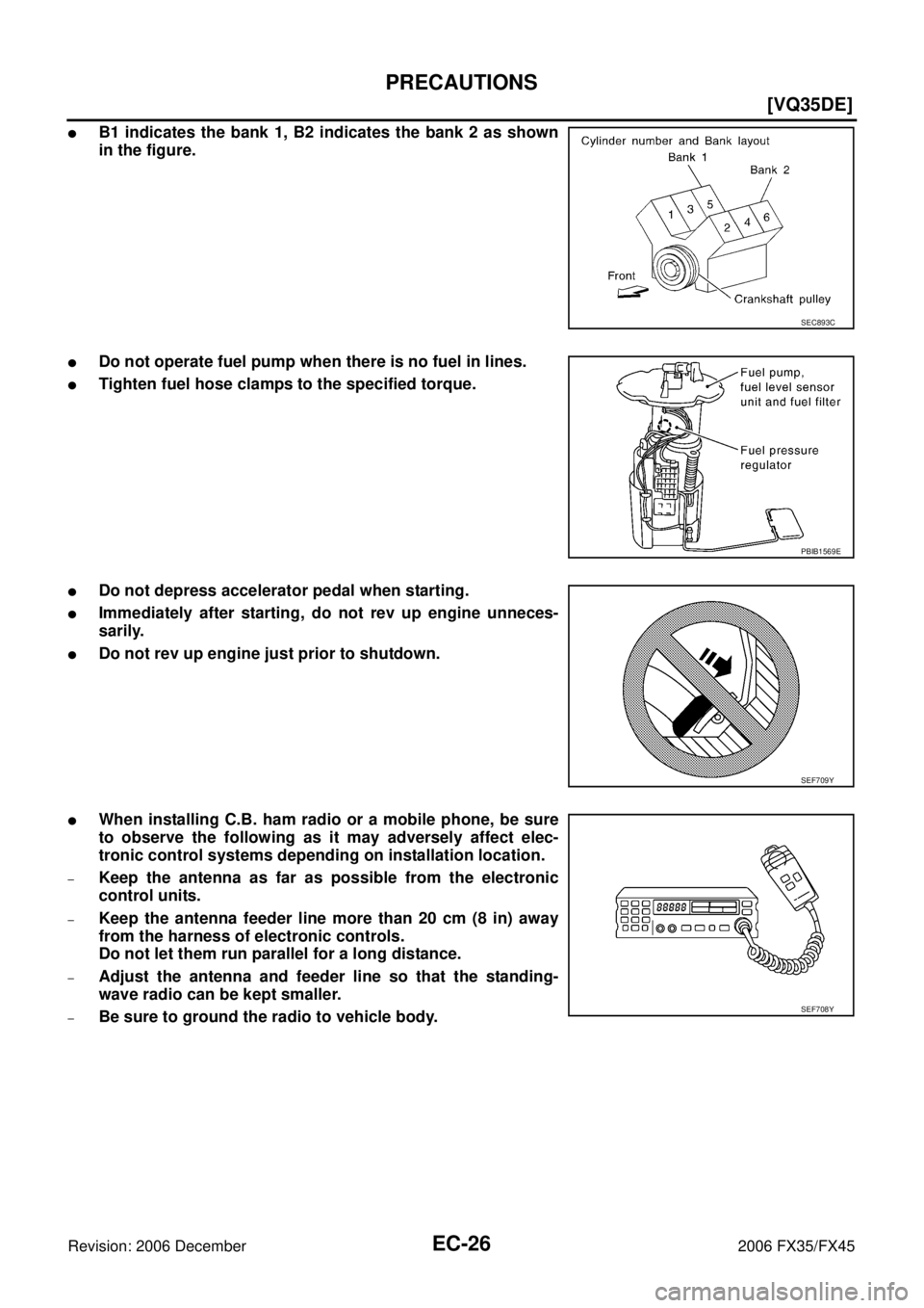
�B1 indicates the bank 1, B2 indicates the bank 2 as shown
in the figure.
�Do not operate fuel pump when there is no fuel in lines.
�Tighten fuel hose clamps to the specified torque.
�Do not depress accelerator pedal when starting.
�Immediately after starting, do not rev up engine unneces-
sarily.
�Do not rev up engine just prior to shutdown.
�When installing C.B. ham radio or a mobile phone, be sure
to observe the following as it may adversely affect elec-
tronic control systems depending on installation location.
–Keep the antenna as far as possible from the electronic
control units.
–Keep the antenna feeder line more than 20 cm (8 in) away
from the harness of electronic controls.
Do not let them run parallel for a long distance.
–Adjust the antenna and feeder line so that the standing-
wave radio can be kept smaller.
–Be sure to ground the radio to vehicle body.
SEC893C
PBIB1569E
SEF709Y
SEF708Y
Page 2071 of 4462
![INFINITI FX35 2006 Service Manual PRECAUTIONS EC-687
[VK45DE]
C
D E
F
G H
I
J
K L
M A
EC
Revision: 2006 December 2006 FX35/FX45
�B1 indicates the bank 1, B2 indicates the bank 2 as shown
in the figure.
�Do not operate fue](/manual-img/42/57019/w960_57019-2070.png "INFINITI FX35 2006 Service Manual PRECAUTIONS EC-687
[VK45DE]
C
D E
F
G H
I
J
K L
M A
EC
Revision: 2006 December 2006 FX35/FX45
�B1 indicates the bank 1, B2 indicates the bank 2 as shown
in the figure.
�Do not operate fue")
PRECAUTIONS EC-687
[VK45DE]
C
D E
F
G H
I
J
K L
M A
EC
Revision: 2006 December 2006 FX35/FX45
�B1 indicates the bank 1, B2 indicates the bank 2 as shown
in the figure.
�Do not operate fuel pump when there is no fuel in lines.
�Tighten fuel hose clamps to the specified torque.
�Do not depress accelerator pedal when starting.
�Immediately after starting, do not rev up engine unneces-
sarily.
�Do not rev up engine just prior to shutdown.
�When installing C.B. ham radio or a mobile phone, be sure
to observe the following as it may adversely affect elec-
tronic control systems depending on installation location.
–Keep the antenna as far as possible from the electronic
control units.
–Keep the antenna feeder line more than 20 cm (8 in) away
from the harness of electronic controls.
Do not let them run parallel for a long distance.
–Adjust the antenna and feeder line so that the standing-
wave radio can be kept smaller.
–Be sure to ground the radio to vehicle body.
PBIB1144E
PBIB1508E
SEF709Y
SEF708Y
Page 3752 of 4462
 terminal 3
�to hazard switch (illumination) terminal 3
�to heated seat switch (driver side) (illumination) terminal")
LT-190
ILLUMINATION
Revision: 2006 December 2006 FX35/FX45
�to clock (illumination) terminal 3
�to hazard switch (illumination) terminal 3
�to heated seat switch (driver side) (illumination) terminal 5
�to heated seat switch (passenger side) (illumination) terminal 5
�to door mirror remote control switch (illumination) terminal 16
�to LDW switch (illumination) terminal 5
�to combination switch (spiral cable) terminal 26
�to microphone terminal 2 (with telephone system)
�to A/C and AV switch (illumination) terminal 3
�to DVD player (illumination) terminal 12
�to coin box illumination terminal 2
�to rear power window switch LH and RH (illumination) terminals 6,
�through combination switch (spiral cable) terminal 18
�to audio steering switch (illumination), and
�to icc steering switch (illumination) (with icc)
�to ascd steering switch (illumination) (without icc)
Illumination control
�through combination meter terminal 19
�to A/T device (illumination) terminal 12
�to snow mode switch (illumination) terminal 6
�to VDC off switch (illumination) terminal 4
�to clock (illumination) terminal 4
�to hazard switch (illumination) terminal 4
�to heated seat switch (driver side) (illumination) terminal 6
�to heated seat switch (passenger side) (illumination) terminal 6
�to door mirror remote control switch terminal 15
�to LDW switch (illumination) terminal 4,
�to combination switch (spiral cable) terminal 27
�to A/C and AV switch (illumination) terminal 4
�to DVD player (illumination) terminal 10,
�through combination switch (spiral cable) terminal 21
�to audio steering switch (illumination), and
�to icc steering switch (illumination) (with icc)
�to ascd steering switch (illumination) (without icc)
Ground is supplied at all times
�to glove box lamp terminal 2, and
�to coin box illumination terminal 3
�through grounds M35, M45 and M85,
�to rear power window switch LH and RH (illumination) terminals 7
�through grounds B15 and B45.
With power and ground supplied, illumination lamps illuminate.
EXTERIOR LAMP BATTERY SAVER CONTROL
When the lighting switch is in the 1ST or 2ND position (or if auto light system is activated), and ignition switch
is turned from ON or ACC to OFF, battery saver control function is activated.
Under this condition, illumination lamps remain illuminated for 5 minutes, then illumination lamps are turned
off.
When the lighting switch is turned from OFF to 1ST or 2ND position (or if auto light system is activated) after
illumination lamps are turned off by battery saver control, and illumination lamps illuminate again.
Exterior lamp battery saver control mode can be changed by the function setting of CONSULT-II.
Page 3918 of 4462

FUELB2 EC Fuel Injection System Function (Bank 2)
H/AIM LT")
PG-66
HARNESS
Revision: 2006 December 2006 FX35/FX45
FTTS EC Fuel Tank Temperature Sensor
FUELB1 EC Fuel Injection System Function (Bank 1)
FUELB2 EC Fuel Injection System Function (Bank 2)
H/AIM LT Headlamp Aiming Control System
H/LAMP LT Headlamp
H/PHON AV Hands Free Telephone
HORN WW Horn
HSEAT SE Heated Seat
I/KEY BL Intelligent Key System
I/MIRR GW Inside Mirror (Auto Anti-Dazzling Mirror)
IATS EC Intake Air Temperature Sensor
ICC ACS Intelligent Cruise Control System
ICC/BS EC ICC Brake Switch
ICC/SW EC ICC Steering Switch
ICCBOF EC ICC Brake Switch
IGNSYS EC Ignition System
ILL LT Illumination
INF/D AV Vehicle Information and Integrated Switch System
INJECT EC Injector
IVCB1 EC Intake Valve Timing Control Solenoid Valve Bank 1
IVCB2 EC Intake Valve Timing Control Solenoid Valve Bank 2
IVCSB1 EC Intake Valve Timing Control Position Sensor Bank 1
IVCSB2 EC Intake Valve Timing Control Position Sensor Bank 2
IVTB1 EC Intake Valve Timing Control System (Bank 1)
IVTB2 EC Intake Valve Timing Control System (Bank 2)
KEYLES BL Remote Keyless Entry System
KS EC Knock Sensor
LDW DI Lane Departure Warning System
M/ANT AV Manual Antenna
MAFS EC Mass Air Flow Sensor
MAIN AT Main Power Supply and Ground Circuit
MAIN EC Main Power Supply and Ground Circuit
MES AV Mobile Entertainment System
METER DI Speedometer, Tachometer, Temp. and Fuel Gauges
MIL/DL EC MIL & Data Link Connectors
MIRROR GW Power Door Mirror
MMSW AT Manual Mode Switch
NATS BL Nissan Anti-Theft System
NAVI AV Navigation System
NONDTC AT Non-Detective Items
O2H2B1 EC Heated Oxygen Sensor 2 Heater Bank 1
O2H2B2 EC Heated Oxygen Sensor 2 Heater Bank 2
O2S2B1 EC Heated Oxygen Sensor 2 Bank 1
O2S2B2 EC Heated Oxygen Sensor 2 Bank 2 Code Section Wiring Diagram Name