Page 2835 of 4462
![INFINITI FX35 2006 Service Manual OIL PAN AND OIL STRAINER EM-41
[VQ35DE]
C
D E
F
G H
I
J
K L
M A
EM
Revision: 2006 December 2006 FX35/FX45
b. Apply a continuous bead of liquid gasket with the tube presser [SST: WS3993000](/manual-img/42/57019/w960_57019-2834.png "INFINITI FX35 2006 Service Manual OIL PAN AND OIL STRAINER EM-41
[VQ35DE]
C
D E
F
G H
I
J
K L
M A
EM
Revision: 2006 December 2006 FX35/FX45
b. Apply a continuous bead of liquid gasket with the tube presser [SST: WS3993000")
OIL PAN AND OIL STRAINER EM-41
[VQ35DE]
C
D E
F
G H
I
J
K L
M A
EM
Revision: 2006 December 2006 FX35/FX45
b. Apply a continuous bead of liquid gasket with the tube presser [SST: WS39930000 ( — )] to the oil pan (lower) as shown in
the figure.
Use Genuine RTV Silicone Sealant or equivalent. Refer to
GI-48, "
RECOMMENDED CHEMICAL PRODUCTS AND
SEALANTS" .
CAUTION:
Attaching should be done within 5 minutes after coating.
c. Install oil pan (lower).
�Tighten mounting bolts in numerical order as shown in the fig-
ure.
5. Install oil pan drain plug.
�Refer to the figure of components of former page for installation direction of drain plug washer. Refer to
EM-35, "
Components (AWD Models)" .
6. Install in the reverse order of removal after this step.
NOTE:
At least 30 minutes after oil pan is installed, pour engine oil.
INSPECTION AFTER INSTALLATION
1. Check the engine oil level and adjust engine oil. Refer to LU-7, "ENGINE OIL" .
2. Start engine, and check there is no leak of engine oil.
3. Stop engine and wait for 10 minutes.
4. Check the engine oil level again. Refer to LU-7, "
ENGINE OIL" .
PBIC2657E
PBIC0782E
Page 2836 of 4462
EM-42
[VQ35DE]
IGNITION COIL
Revision: 2006 December 2006 FX35/FX45
IGNITION COILPFP:22448
ComponentsNBS003GF
Removal and InstallationNBS003GG
REMOVAL
1. Remove engine cover with power tool. Refer to EM-19, "INTAKE MANIFOLD COLLECTOR" .
2. Remove air duct (At the left bank side, remove ignition coil). Refer to EM-17, "
AIR CLEANER AND AIR
DUCT" .
3. Move aside harness, harness bracket, and hoses located above ignition coil.
4. Disconnect harness connector from ignition coil.
5. Remove ignition coil. CAUTION:
Do not shock it.
INSTALLATION
Installation is the reverse order of removal.
1. Ignition coil 2. Spark plug 3. Rocker cover (left bank)
A. Left bank
PBIC4359E
Page 2837 of 4462
![INFINITI FX35 2006 Service Manual SPARK PLUG (PLATINUM-TIPPED TYPE) EM-43
[VQ35DE]
C
D E
F
G H
I
J
K L
M A
EM
Revision: 2006 December 2006 FX35/FX45
SPARK PLUG (PLATINUM-TIPPED TYPE)PFP:22401
ComponentsNBS003GH
Removal and](/manual-img/42/57019/w960_57019-2836.png "INFINITI FX35 2006 Service Manual SPARK PLUG (PLATINUM-TIPPED TYPE) EM-43
[VQ35DE]
C
D E
F
G H
I
J
K L
M A
EM
Revision: 2006 December 2006 FX35/FX45
SPARK PLUG (PLATINUM-TIPPED TYPE)PFP:22401
ComponentsNBS003GH
Removal and")
SPARK PLUG (PLATINUM-TIPPED TYPE) EM-43
[VQ35DE]
C
D E
F
G H
I
J
K L
M A
EM
Revision: 2006 December 2006 FX35/FX45
SPARK PLUG (PLATINUM-TIPPED TYPE)PFP:22401
ComponentsNBS003GH
Removal and InstallationNBS003GI
REMOVAL
1. Remove engine cover with power tool. Refer to EM-19, "INTAKE MANIFOLD COLLECTOR" .
2. Remove ignition coil. Refer to EM-42, "
IGNITION COIL" .
3. Remove spark plug with a spark plug wrench (commercial ser- vice tool).
INSPECTION AFTER REMOVAL
Use the standard type spark plug for normal condition.
The hot type spark plug is suitable when fouling occurs with the standard type spark plug under conditions
such as:
�Frequent engine starts
�Low ambient temperatures
The cold type spark plug is suitable when spark knock occurs with the standard type spark plug under condi-
tions such as:
�Extended highway driving
�Frequent high engine revolution
1. Ignition coil 2. Spark plug 3. Rocker cover (left bank)
A. Left bank
PBIC4359E
SEM294A
Make NGK
Standard type PLFR5A-11
Hot type PLFR4A-11
Cold type PLFR6A-11
Page 2838 of 4462
EM-44
[VQ35DE]
SPARK PLUG (PLATINUM-TIPPED TYPE)
Revision: 2006 December 2006 FX35/FX45
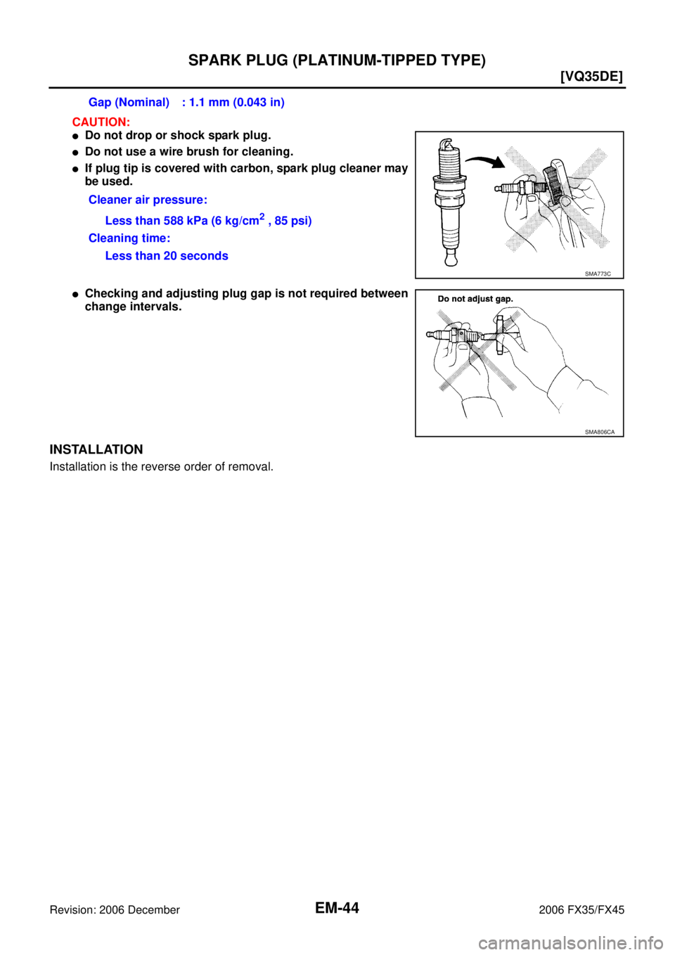
CAUTION:
�Do not drop or shock spark plug.
�Do not use a wire brush for cleaning.
�If plug tip is covered with carbon, spark plug cleaner may
be used.
�Checking and adjusting plug gap is not required between
change intervals.
INSTALLATION
Installation is the reverse order of removal. Gap (Nominal) : 1.1 mm (0.043 in)
Cleaner air pressure: Less than 588 kPa (6 kg/cm
2 , 85 psi)
Cleaning time: Less than 20 seconds
SMA773C
SMA806CA
Page 2839 of 4462
![INFINITI FX35 2006 Service Manual FUEL INJECTOR AND FUEL TUBE EM-45
[VQ35DE]
C
D E
F
G H
I
J
K L
M A
EM
Revision: 2006 December 2006 FX35/FX45
FUEL INJECTOR AND FUEL TUBEPFP:16600
ComponentsNBS003GJ
CAUTION:
Do not remove](/manual-img/42/57019/w960_57019-2838.png "INFINITI FX35 2006 Service Manual FUEL INJECTOR AND FUEL TUBE EM-45
[VQ35DE]
C
D E
F
G H
I
J
K L
M A
EM
Revision: 2006 December 2006 FX35/FX45
FUEL INJECTOR AND FUEL TUBEPFP:16600
ComponentsNBS003GJ
CAUTION:
Do not remove")
FUEL INJECTOR AND FUEL TUBE EM-45
[VQ35DE]
C
D E
F
G H
I
J
K L
M A
EM
Revision: 2006 December 2006 FX35/FX45
FUEL INJECTOR AND FUEL TUBEPFP:16600
ComponentsNBS003GJ
CAUTION:
Do not remove or disassemble parts unless instructed as shown in the figure.
Removal and InstallationNBS003GK
REMOVAL
WARNING:
�Put a “CAUTION FLAMMABLE” sign in the workshop.
�Be sure to work in a well ventilated area and furnish workshop with a CO2 fire extinguisher.
�Do not smoke while servicing fuel system. Keep open flames and sparks away from the work area.
�To avoid the danger of being scalded, do not drain engine coolant when the engine is hot.
1. Remove engine cover with power tool. Refer to EM-19, "
INTAKE MANIFOLD COLLECTOR" .
2. Release fuel pressure. Refer to EC-86, "
FUEL PRESSURE RELEASE" .
3. Drain engine coolant, or when water hoses are disconnected, attach plug to prevent engine coolant leak- age. Refer to CO-11, "
Changing Engine Coolant" and EM-19, "INTAKE MANIFOLD COLLECTOR" .
CAUTION:
Perform this step when the engine is cold.
1. Fuel damper 2. O-ring 3. Fuel sub-tube
4. EVAP hose 5. Intake manifold collector (lower) 6. Fuel feed hose (with damper)
7. Fuel tube 8. Spacer 9. Clip
10. O-ring (blue) 11. Fuel injector 12. O-ring (brown)
13. Hose clamp 14. Bracket 15. Quick connector cap
16. Centralized under-floor piping
SBIA0580E
Page 2840 of 4462
![INFINITI FX35 2006 Service Manual EM-46
[VQ35DE]
FUEL INJECTOR AND FUEL TUBE
Revision: 2006 December 2006 FX35/FX45
4. Remove fuel feed hose (with damper) from fuel sub-tube. NOTE:
There is no fuel return route.
CAUTION:
�While hose](/manual-img/42/57019/w960_57019-2839.png "INFINITI FX35 2006 Service Manual EM-46
[VQ35DE]
FUEL INJECTOR AND FUEL TUBE
Revision: 2006 December 2006 FX35/FX45
4. Remove fuel feed hose (with damper) from fuel sub-tube. NOTE:
There is no fuel return route.
CAUTION:
�While hose")
EM-46
[VQ35DE]
FUEL INJECTOR AND FUEL TUBE
Revision: 2006 December 2006 FX35/FX45
4. Remove fuel feed hose (with damper) from fuel sub-tube. NOTE:
There is no fuel return route.
CAUTION:
�While hoses are disconnected, plug them to prevent fuel
from draining.
�Do not separate damper and hose.
5. When separating fuel feed hose (with damper) and centralized under-floor piping connection, disconnect quick connector as the following:
a. Remove quick connector cap from quick connector connection on right member side.
b. Disconnect fuel feed hose (with damper) from bracket hose clamp.
c. Disconnect quick connector from centralized under-floor piping as follows: CAUTION:
Disconnect quick connector by using quick connector release [SST: — (J-45488)], not by picking
out retainer tabs.
i. With the sleeve side of quick connector release facing quick connector, install quick connector release onto centralized under-floor piping.
ii. Insert quick connector release into quick connector until sleeve contacts and goes no further. Hold quick connector release on
that position.
CAUTION:
Inserting quick connector release hard will not disconnect
quick connector. Hold quick connector release where it
contacts and goes no further.
iii. Draw and pull out quick connector straight from centralized under-floor piping.
CAUTION:
�Pull quick connector holding “A” position as shown in
the figure.
�Do not pull with lateral force applied. O-ring inside quick connector may be damaged.
�Prepare container and cloth beforehand as fuel will leak out.
�Avoid fire and sparks.
�Keep parts away from heat source. Especially, be careful when welding is performed around
them.
�Do not expose parts to battery electrolyte or other acids.
�Do not bend or twist connection between quick connector and fuel feed hose (with damper) dur-
ing installation/removal.
KBIA1293E
PBIC2083E
PBIC1898E
Page 2841 of 4462
![INFINITI FX35 2006 Service Manual FUEL INJECTOR AND FUEL TUBE EM-47
[VQ35DE]
C
D E
F
G H
I
J
K L
M A
EM
Revision: 2006 December 2006 FX35/FX45
�To keep clean the connecting portion and to avoid dam-
age and foreign materi](/manual-img/42/57019/w960_57019-2840.png "INFINITI FX35 2006 Service Manual FUEL INJECTOR AND FUEL TUBE EM-47
[VQ35DE]
C
D E
F
G H
I
J
K L
M A
EM
Revision: 2006 December 2006 FX35/FX45
�To keep clean the connecting portion and to avoid dam-
age and foreign materi")
FUEL INJECTOR AND FUEL TUBE EM-47
[VQ35DE]
C
D E
F
G H
I
J
K L
M A
EM
Revision: 2006 December 2006 FX35/FX45
�To keep clean the connecting portion and to avoid dam-
age and foreign materials, cover them completely with
plastic bags or something similar.
6. Remove intake manifold collectors (upper and lower). Refer to EM-19, "
INTAKE MANIFOLD COLLEC-
TOR" .
7. Disconnect harness connector from fuel injector.
8. Loosen mounting bolts in reverse order as shown in the figure, and remove fuel tube and fuel injector assembly.
CAUTION:
Do not tilt it, or remaining fuel in pipes may flow out from
pipes.
9. Remove spacers on intake manifold.
10. Remove fuel injector from fuel tube as follows:
a. Open and remove clip.
b. Remove fuel injector from fuel tube by pulling straight. CAUTION:
�Be careful with remaining fuel that may go out from fuel
tube.
�Be careful not to damage injector nozzles during
removal.
�Do not bump or drop fuel injector.
�Do not disassemble fuel injector.
11. Remove fuel sub-tube and fuel damper.
INSTALLATION
1. Install fuel damper and fuel sub-tube.
�When handling new O-rings, be careful of the following caution:
CAUTION:
�Handle O-ring with bare hands. Do not wear gloves.
PBIC1899E
KBIA1296E
PBIC2470E
Page 2843 of 4462
![INFINITI FX35 2006 Service Manual FUEL INJECTOR AND FUEL TUBE EM-49
[VQ35DE]
C
D E
F
G H
I
J
K L
M A
EM
Revision: 2006 December 2006 FX35/FX45
�Tighten mounting bolts in two steps in numerical order as
shown in the figure](/manual-img/42/57019/w960_57019-2842.png "INFINITI FX35 2006 Service Manual FUEL INJECTOR AND FUEL TUBE EM-49
[VQ35DE]
C
D E
F
G H
I
J
K L
M A
EM
Revision: 2006 December 2006 FX35/FX45
�Tighten mounting bolts in two steps in numerical order as
shown in the figure")
FUEL INJECTOR AND FUEL TUBE EM-49
[VQ35DE]
C
D E
F
G H
I
J
K L
M A
EM
Revision: 2006 December 2006 FX35/FX45
�Tighten mounting bolts in two steps in numerical order as
shown in the figure.
6. Connect injector sub-harness.
7. Install intake manifold collectors (upper and lower). Refer to EM-19, "
INTAKE MANIFOLD COLLECTOR" .
8. Install fuel sub-tube on rear end of intake manifold collector (lower).
9. Connect fuel feed hose (with damper).
�Handling procedure of O-ring is the same as that of fuel damper and fuel sub-tube.
�Insert fuel damper straight into fuel sub-tube.
�Tighten mounting bolts evenly in turn.
�After tightening mounting bolts, make sure that there is no gap between flange and fuel sub-tube.
10. Connect quick connector between fuel feed hose (with damper) and centralized under-floor piping con- nection as follows:
a. Make sure no foreign substances are deposited in and around centralized under-floor piping and quick connector, and no damage on them.
b. Thinly apply new engine oil around centralized under-floor piping from tip end to spool end.
c. Align center to insert quick connector straightly into centralized under-floor piping.
�Insert quick connector to centralized under-floor piping until
top spool is completely inside quick connector, and 2nd level
spool exposes right below quick connector.
CAUTION:
�Hold “A” position as shown in the figure when inserting
centralized under-floor piping into quick connector.
�Carefully align center to avoid inclined insertion to pre-
vent damage to O-ring inside quick connector.
�Insert until you hear a “click” sound and actually feel the
engagement.
�To avoid misidentification of engagement with a similar
sound, be sure to perform the next step.
d. Pull quick connector by hand holding “A” position. Make sure it is completely engaged (connected) so that it does not come out from centralized under-floor piping.
e. Install quick connector cap to quick connector connection.
�Install quick connector cap with arrow on surface facing in
direction of quick connector (fuel feed hose side).
CAUTION:
If quick connector cap cannot be installed smoothly, quick
connector may have not been installed correctly. Check the
connection again.
11. Install in the reverse order of removal after this step. 1st step
: 10.1 N·m (1.0 kg-m, 7 ft-lb)
2nd step : 23.6 N·m (2.4 kg-m, 17 ft-lb)
KBIA1296E
PBIC2471E
KBIA1298E
![INFINITI FX35 2006 Service Manual EM-42
[VQ35DE]
IGNITION COIL
Revision: 2006 December 2006 FX35/FX45
IGNITION COILPFP:22448
ComponentsNBS003GF
Removal and InstallationNBS003GG
REMOVAL
1. Remove engine cover with power tool. Refer to](/manual-img/42/57019/w960_57019-2835.png "INFINITI FX35 2006 Service Manual EM-42
[VQ35DE]
IGNITION COIL
Revision: 2006 December 2006 FX35/FX45
IGNITION COILPFP:22448
ComponentsNBS003GF
Removal and InstallationNBS003GG
REMOVAL
1. Remove engine cover with power tool. Refer to")