Page 2811 of 4462
![INFINITI FX35 2006 Service Manual AIR CLEANER AND AIR DUCT EM-17
[VQ35DE]
C
D E
F
G H
I
J
K L
M A
EM
Revision: 2006 December 2006 FX35/FX45
AIR CLEANER AND AIR DUCTPFP:16500
ComponentsNBS003G2
Removal and InstallationNBS00](/manual-img/42/57019/w960_57019-2810.png "INFINITI FX35 2006 Service Manual AIR CLEANER AND AIR DUCT EM-17
[VQ35DE]
C
D E
F
G H
I
J
K L
M A
EM
Revision: 2006 December 2006 FX35/FX45
AIR CLEANER AND AIR DUCTPFP:16500
ComponentsNBS003G2
Removal and InstallationNBS00")
AIR CLEANER AND AIR DUCT EM-17
[VQ35DE]
C
D E
F
G H
I
J
K L
M A
EM
Revision: 2006 December 2006 FX35/FX45
AIR CLEANER AND AIR DUCTPFP:16500
ComponentsNBS003G2
Removal and InstallationNBS003G3
REMOVAL
1. Remove engine cover with power tool. Refer to EM-19, "INTAKE MANIFOLD COLLECTOR" .
�This work is unnecessary when parts located forward of mass air flow sensor are removed/installed.
2. Remove air duct (inlet) and power duct.
3. Disconnect mass air flow sensor harness connector.
4. Disconnect PCV hose.
5. Remove air cleaner case/mass air flow sensor and air duct disconnecting their joints.
�Add marks as necessary for easier installation.
6. Remove mass air flow sensor from air cleaner case. CAUTION:
Handle mass air flow sensor with the following cares.
�Do not shock it.
�Do not disassemble it.
�Do not touch its sensor.
7. Remove resonator in fender, lifting left fender protector.
INSPECTION AFTER REMOVAL
Inspect air hoses for cracks or tear.
1. Air hose 2. PCV hose 3. Air duct
4. Air hose 5. Power duct 6. Clip
7. Air duct (inlet) 8. Resonator 9. Grommet
10. Air cleaner case 11. Air cleaner filter 12. Air cleaner case
13. O-ring 14. Mass air flow sensor
SBIA0462E
Page 2812 of 4462
![INFINITI FX35 2006 Service Manual EM-18
[VQ35DE]
AIR CLEANER AND AIR DUCT
Revision: 2006 December 2006 FX35/FX45
�If anything found replace air hose.
INSTALLATION
Note the following, and install in the reverse order of removal.
�Align](/manual-img/42/57019/w960_57019-2811.png "INFINITI FX35 2006 Service Manual EM-18
[VQ35DE]
AIR CLEANER AND AIR DUCT
Revision: 2006 December 2006 FX35/FX45
�If anything found replace air hose.
INSTALLATION
Note the following, and install in the reverse order of removal.
�Align")
EM-18
[VQ35DE]
AIR CLEANER AND AIR DUCT
Revision: 2006 December 2006 FX35/FX45
�If anything found replace air hose.
INSTALLATION
Note the following, and install in the reverse order of removal.
�Align marks. Attach each joint. Screw clamps firmly.
�To position air cleaner case, refer to EM-18, "Changing Air Cleaner Filter" .
Changing Air Cleaner FilterNBS003G4
INSPECTION
Check status (fouling, damage, etc.) of air cleaner filter at power duct
hole.
REMOVAL
Removal in the order below.
1. Remove air duct (inlet) from air cleaner case.
2. Disconnect harness connector from mass air flow sensor.
3. Loosen clamp bolts of air hose.
4. Remove mounting bolts for air cleaner case. Remove air cleaner case/mass air flow sensor/air hose assembly.
5. Unhook clips and open air cleaner case, and remove air cleaner filter.
INSTALLATION
Note the following, and install in the reverse order of removal.
�If grommet at bottom of air cleaner case comes off together with
air cleaner case, fix it to vehicle before installation.
�Look at internal bottom face through power duct hole, and posi-
tion air cleaner case with resonator upper end circle and air
cleaner case round hole aligned. Then push air cleaner case
straight down.
�At this time, check by hand if protrusion at bottom of air cleaner
case has been inserted into grommet on vehicle side.
�Clip power duct with bulge on reverse side of lower end
engaged with air cleaner case.
SBIA0463E
SBIA0464E
KBIA0954E
Page 2813 of 4462
INTAKE MANIFOLD COLLECTOR EM-19
[VQ35DE]
C
D E
F
G H
I
J
K L
M A
EM
Revision: 2006 December 2006 FX35/FX45
INTAKE MANIFOLD COLLECTORPFP:14003
ComponentsNBS003G5
Removal and InstallationNBS003G6
REMOVAL
WARNING:
�To avoid the danger of being scalded, never drain engine coolant when the engine is hot.
�Gasket for intake manifold collector (upper) is secured together with mounting bolt for intake man-
ifold collector (lower). Thus, even when only gasket for upper side is replaced, gasket for lower
side must be also replaced.
1. Electric throttle control actuator 2. Gasket 3. Vacuum hose
4. EVAP canister purge volume control
solenoid valve 5. Bracket 6. Intake manifold collector (upper)
7. Intake manifold collector cover 8. Gasket 9. Water hose
10. Bracket 11. Water hose 12. PCV hose
13. Intake manifold collector (lower)
SBIA0585E
Page 2815 of 4462
INTAKE MANIFOLD COLLECTOR EM-21
[VQ35DE]
C
D E
F
G H
I
J
K L
M A
EM
Revision: 2006 December 2006 FX35/FX45
8. Loosen mounting bolts in reverse order of illustration to remove intake manifold collector (upper) with power tool.
9. Remove PCV hose [between intake manifold collector (lower) and rocker cover (right bank)].
10. Loosen mounting bolts in reverse order as shown in the figure, and remove intake manifold collector cover, gasket, intake man-
ifold collector (lower) and gasket with power tool.
CAUTION:
Cover engine openings to avoid entry of foreign materials.
INSPECTION AFTER REMOVAL
Surface Distortion
�Check the surface distortion of both the intake manifold collector
(upper and lower) mating surfaces with a straightedge and a
feeler gauge.
�If it exceeds the limit, replace intake manifold collector (upper
and/or lower).
PBIC0773E
PBIC0774E
Limit : 0.1 mm (0.004 in)
PBIC0775E
Page 2816 of 4462
![INFINITI FX35 2006 Service Manual EM-22
[VQ35DE]
INTAKE MANIFOLD COLLECTOR
Revision: 2006 December 2006 FX35/FX45
INSTALLATION
Note the following, and install in the reverse order of removal.
Part Installation Direction
Referring to f](/manual-img/42/57019/w960_57019-2815.png "INFINITI FX35 2006 Service Manual EM-22
[VQ35DE]
INTAKE MANIFOLD COLLECTOR
Revision: 2006 December 2006 FX35/FX45
INSTALLATION
Note the following, and install in the reverse order of removal.
Part Installation Direction
Referring to f")
EM-22
[VQ35DE]
INTAKE MANIFOLD COLLECTOR
Revision: 2006 December 2006 FX35/FX45
INSTALLATION
Note the following, and install in the reverse order of removal.
Part Installation Direction
Referring to front marks, install parts shown in figure.
Intake Manifold Collector (Lower)
Tighten mounting bolts in numerical order as shown in the figure.
NOTE:
Tighten mounting bolts to secure gasket (lower), intake manifold col-
lector (lower), gasket (upper), and intake manifold collector cover.
Intake Manifold Collector (Upper)
�If stud bolts were removed, install them and tighten to the specified torque below.
�Shank length under bolt head varies with bolt location. Install
mounting bolts while referring to numbers shown below and in
the figure. (Bolt length does not include pilot portion.)
�Tighten mounting bolts in numerical order as shown in the fig-
ure.
Water Hose
�Insert hose by 27 to 32 mm (1.06 to 1.26 in) from connector end.
PBIC0776E
PBIC0774E
: 5.9 N·m (0.6 kg-m, 52 in-lb)
Bolt M6 × 25 mm (0.98 in) : 7, 8, 10, 11, 13, 14, 15, 16, 18
M6 × 45 mm (1.77 in) : 2, 4, 5
M6 × 60 mm (2.36 in) : 1, 3, 6, 9
M6 Nut : 12, 17
PBIC0773E
Page 2818 of 4462
EM-24
[VQ35DE]
INTAKE MANIFOLD
Revision: 2006 December 2006 FX35/FX45
INTAKE MANIFOLDPFP:14003
ComponentsNBS003G7
Removal and InstallationNBS003G8
REMOVAL
1. Release fuel pressure. Refer to EC-86, "FUEL PRESSURE RELEASE" .
2. Remove intake manifold collectors (upper and lower). Refer to EM-19, "
INTAKE MANIFOLD COLLEC-
TOR" .
3. Remove fuel tube and fuel injector assembly. Refer to EM-45, "
FUEL INJECTOR AND FUEL TUBE" .
4. Loosen mounting bolts and nuts in reverse order as shown in the figure to remove intake manifold with power tool.
5. Remove gaskets. CAUTION:
Cover engine openings to avoid entry of foreign materials.
1. Harness bracket 2. Intake manifold 3. Gasket
SBIA0487E
PBIC0778E
Page 2819 of 4462
INTAKE MANIFOLD EM-25
[VQ35DE]
C
D E
F
G H
I
J
K L
M A
EM
Revision: 2006 December 2006 FX35/FX45
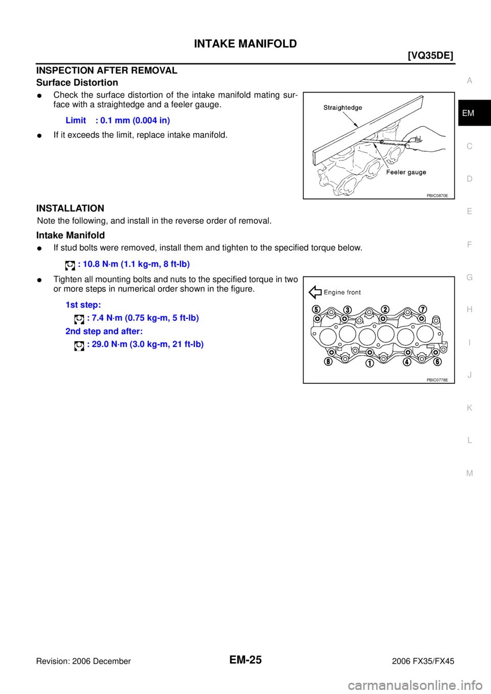
INSPECTION AFTER REMOVAL
Surface Distortion
�Check the surface distortion of the intake manifold mating sur-
face with a straightedge and a feeler gauge.
�If it exceeds the limit, replace intake manifold.
INSTALLATION
Note the following, and install in the reverse order of removal.
Intake Manifold
�If stud bolts were removed, install them and tighten to the specified torque below.
�Tighten all mounting bolts and nuts to the specified torque in two
or more steps in numerical order shown in the figure. Limit : 0.1 mm (0.004 in)
PBIC0870E
: 10.8 N·m (1.1 kg-m, 8 ft-lb)
1st step: : 7.4 N·m (0.75 kg-m, 5 ft-lb)
2nd step and after: : 29.0 N·m (3.0 kg-m, 21 ft-lb)
PBIC0778E
Page 2820 of 4462
![INFINITI FX35 2006 Service Manual EM-26
[VQ35DE]
EXHAUST MANIFOLD AND THREE WAY CATALYST
Revision: 2006 December 2006 FX35/FX45
EXHAUST MANIFOLD AND THREE WAY CATALYSTPFP:14004
ComponentsNBS003G9
Removal and InstallationNBS003GA
REMOV](/manual-img/42/57019/w960_57019-2819.png "INFINITI FX35 2006 Service Manual EM-26
[VQ35DE]
EXHAUST MANIFOLD AND THREE WAY CATALYST
Revision: 2006 December 2006 FX35/FX45
EXHAUST MANIFOLD AND THREE WAY CATALYSTPFP:14004
ComponentsNBS003G9
Removal and InstallationNBS003GA
REMOV")
EM-26
[VQ35DE]
EXHAUST MANIFOLD AND THREE WAY CATALYST
Revision: 2006 December 2006 FX35/FX45
EXHAUST MANIFOLD AND THREE WAY CATALYSTPFP:14004
ComponentsNBS003G9
Removal and InstallationNBS003GA
REMOVAL
WARNING:
Perform the work when the exhaust and cooling system have completely cooled down.
1. Remove engine cover with power tool. Refer to EM-19, "
INTAKE MANIFOLD COLLECTOR" .
2. Drain engine coolant. Refer to CO-11, "
Changing Engine Coolant" .
CAUTION:
�Perform this step when the engine is cold.
�Do not spill engine coolant on drive belts.
3. Remove air cleaner case and air duct. Refer to EM-17, "
AIR CLEANER AND AIR DUCT" .
4. Remove front and rear engine undercover and front cross bar with power tool.
5. Disconnect heated oxygen sensors 2 (bank 1 and bank 2) harness connectors.
1. Heated oxygen sensor 2 (bank 1) 2. Three way catalyst (right bank) 3. Gasket
4. Air fuel ratio sensor 1 (bank 1) 5. Exhaust manifold cover (right bank) 6. Exhaust manifold (right bank)
7. Exhaust manifold (left bank) 8. Exhaust manifold cover (left bank) 9. Three way catalyst (left bank)
10. Air fuel ratio sensor 1 (bank 2) 11. Heated oxygen sensor 2 (bank 2)
PBIC3103E
![INFINITI FX35 2006 Service Manual INTAKE MANIFOLD COLLECTOR EM-19
[VQ35DE]
C
D E
F
G H
I
J
K L
M A
EM
Revision: 2006 December 2006 FX35/FX45
INTAKE MANIFOLD COLLECTORPFP:14003
ComponentsNBS003G5
Removal and InstallationNBS](/manual-img/42/57019/w960_57019-2812.png "INFINITI FX35 2006 Service Manual INTAKE MANIFOLD COLLECTOR EM-19
[VQ35DE]
C
D E
F
G H
I
J
K L
M A
EM
Revision: 2006 December 2006 FX35/FX45
INTAKE MANIFOLD COLLECTORPFP:14003
ComponentsNBS003G5
Removal and InstallationNBS")
![INFINITI FX35 2006 Service Manual INTAKE MANIFOLD COLLECTOR EM-21
[VQ35DE]
C
D E
F
G H
I
J
K L
M A
EM
Revision: 2006 December 2006 FX35/FX45
8. Loosen mounting bolts in reverse order of illustration to remove intake manif](/manual-img/42/57019/w960_57019-2814.png "INFINITI FX35 2006 Service Manual INTAKE MANIFOLD COLLECTOR EM-21
[VQ35DE]
C
D E
F
G H
I
J
K L
M A
EM
Revision: 2006 December 2006 FX35/FX45
8. Loosen mounting bolts in reverse order of illustration to remove intake manif")
![INFINITI FX35 2006 Service Manual EM-24
[VQ35DE]
INTAKE MANIFOLD
Revision: 2006 December 2006 FX35/FX45
INTAKE MANIFOLDPFP:14003
ComponentsNBS003G7
Removal and InstallationNBS003G8
REMOVAL
1. Release fuel pressure. Refer to EC-86, "F](/manual-img/42/57019/w960_57019-2817.png "INFINITI FX35 2006 Service Manual EM-24
[VQ35DE]
INTAKE MANIFOLD
Revision: 2006 December 2006 FX35/FX45
INTAKE MANIFOLDPFP:14003
ComponentsNBS003G7
Removal and InstallationNBS003G8
REMOVAL
1. Release fuel pressure. Refer to EC-86, \"F")