Page 3097 of 4462
![INFINITI FX35 2006 Service Manual NOISE, VIBRATION AND HARSHNESS (NVH) TROUBLESHOOTING FAX-9
[AWD]
C E F
G H
I
J
K L
M A
B
FA X
Revision: 2006 December 2006 FX35/FX45
NOISE, VIBRATION AND HARSHNESS (NVH) TROUBLESHOOTINGPFP:](/manual-img/42/57019/w960_57019-3096.png "INFINITI FX35 2006 Service Manual NOISE, VIBRATION AND HARSHNESS (NVH) TROUBLESHOOTING FAX-9
[AWD]
C E F
G H
I
J
K L
M A
B
FA X
Revision: 2006 December 2006 FX35/FX45
NOISE, VIBRATION AND HARSHNESS (NVH) TROUBLESHOOTINGPFP:")
NOISE, VIBRATION AND HARSHNESS (NVH) TROUBLESHOOTING FAX-9
[AWD]
C E F
G H
I
J
K L
M A
B
FA X
Revision: 2006 December 2006 FX35/FX45
NOISE, VIBRATION AND HARSHNESS (NVH) TROUBLESHOOTINGPFP:00003
NVH Troubleshooting ChartNDS000C3
Use chart below to help you find the cause of the symptom. If necessary, repair or replace these parts.
× : Applicable Reference page
—
FAX-15—
FAX-10—
FAX-10
NVH in FFD section
NVH in FAX and FSU section
Refer to FRONT AXLE in this chart. NVH in WT section
NVH in WT section
Refer to DRIVE SHAFT in this chart. NVH in BR section
NVH in PS section
Possible cause and SUSPECTED PARTS
Excessive joint angle
Joint sliding resistance
Imbalance
Improper installation, looseness
Parts interference
Wheel bearing damage
FRONT DIFFERENTIAL
FRONT AXLE AND FRONT SUSPENSION
FRONT AXLE
TIRES
ROAD WHEEL
DRIVE SHAFT
BRAKES
STEERING
Symptom DRIVE
SHAFT Noise
×× ×××××× ××
Shake ×× ×××××××
FRONT
AXLE Noise
×××× ××××××
Shake ××× ××××××
Vibration ××× ××××
Shimmy ×× ××× ××
Judder ××××××
Poor quality ride or handling ×× ×××
Page 3098 of 4462
![INFINITI FX35 2006 Service Manual FAX-10
[AWD]
FRONT WHEEL HUB AND KNUCKLE
Revision: 2006 December 2006 FX35/FX45
FRONT WHEEL HUB AND KNUCKLEPFP:40202
On-Vehicle Inspection NDS000D0
Make sure the mounting conditions (looseness, back l](/manual-img/42/57019/w960_57019-3097.png "INFINITI FX35 2006 Service Manual FAX-10
[AWD]
FRONT WHEEL HUB AND KNUCKLE
Revision: 2006 December 2006 FX35/FX45
FRONT WHEEL HUB AND KNUCKLEPFP:40202
On-Vehicle Inspection NDS000D0
Make sure the mounting conditions (looseness, back l")
FAX-10
[AWD]
FRONT WHEEL HUB AND KNUCKLE
Revision: 2006 December 2006 FX35/FX45
FRONT WHEEL HUB AND KNUCKLEPFP:40202
On-Vehicle Inspection NDS000D0
Make sure the mounting conditions (looseness, back lash) of each component and component status (wear,
damage) are normal.
WHEEL BEARING INSPECTION
�Move wheel hub in the axial direction by hand. Check that there is no looseness of front wheel bearing.
�Rotate wheel hub and make sure there is no unusual noise or other irregular conditions. If there are any
irregular conditions, replace wheel hub and bearing assembly.
Removal and InstallationNDS000C5
COMPONENTS
REMOVAL
1. Remove tires from vehicle with power tool.
2. Remove brake caliper with power tool. Hang it in a place where it will not interfere with work. Refer to BR-
20, "Removal and Installation of Brake Caliper Assembly" .
NOTE:
Avoid depressing brake pedal while brake caliper is removed.
3. Put alignment marks on disc rotor and wheel hub and bearing assembly, then remove disc rotor.
4. Remove wheel sensor from steering knuckle. Refer to BRC-55,
"WHEEL SENSORS"
CAUTION:
Do not pull on wheel sensor harness.
5. Remove cotter pin, then remove lock nut from drive shaft.
6. Remove steering outer socket and cotter pin at steering knuckle, then loosen mounting nut. Axial end play : 0.05 mm (0.002 in) or less
1. Cotter pin 2. Washer 3. Disc rotor
4. Wheel hub and bearing assembly 5. Splash guard 6. Steering knuckle
Refer to GI-11, "
Components" , for the symbols in the figure.
PDIA1217E
SDIA1480E
Page 3100 of 4462
![INFINITI FX35 2006 Service Manual FAX-12
[AWD]
FRONT DRIVE SHAFT
Revision: 2006 December 2006 FX35/FX45
FRONT DRIVE SHAFTPFP:39100
Removal and Installation (Left Side)NDS000C6
COMPONENTS
REMOVAL
1. Remove tires from vehicle with powe](/manual-img/42/57019/w960_57019-3099.png "INFINITI FX35 2006 Service Manual FAX-12
[AWD]
FRONT DRIVE SHAFT
Revision: 2006 December 2006 FX35/FX45
FRONT DRIVE SHAFTPFP:39100
Removal and Installation (Left Side)NDS000C6
COMPONENTS
REMOVAL
1. Remove tires from vehicle with powe")
FAX-12
[AWD]
FRONT DRIVE SHAFT
Revision: 2006 December 2006 FX35/FX45
FRONT DRIVE SHAFTPFP:39100
Removal and Installation (Left Side)NDS000C6
COMPONENTS
REMOVAL
1. Remove tires from vehicle with power tool.
2. Remove undercover with power tool.
3. Remove cotter pin. Then remove lock nut from drive shaft with power tool.
4. Remove wheel sensor harness from strut assembly. Refer to BRC-55, "
WHEEL SENSORS" .
CAUTION:
Do not pull on wheel sensor harness.
5. Remove brake hose lock plate. Then remove brake hose from strut assembly. Refer to BR-11, "
BRAKE
TUBE AND HOSE" .
6. Remove fixing bolts and nuts between strut assembly and steering knuckle with power tool.
7. Using a puller (suitable tool), remove drive shaft from steering knuckle.
CAUTION:
When removing drive shaft, do not apply an excessive
angle to drive shaft joint. Also be careful not to excessively
extend slide joint.
8. Remove fixing bolt of front final drive side assembly drive shaft with power tool, then remove drive shaft from vehicle.
INSPECTION AFTER REMOVAL
�Move joint up/down, left /right, and in the axial direction. Check for any rough movement or significant
looseness.
�Check boot for cracks or other damage, and also for grease
leakage.
�If a trouble is found, disassemble drive shaft, and then replace
with new one.
INSTALLATION
�Refer to FA X - 1 2 , "Removal and Installation (Left Side)" for tightening torque. Install in the reverse order of
removal.
1. Cotter pin 2. Washer 3. Drive shaft
Refer to GI-11, "
Components" , for the symbols in the figure.
PDIA1218E
SDIA0972J
SDIA1046J
Page 3101 of 4462
![INFINITI FX35 2006 Service Manual FRONT DRIVE SHAFT FAX-13
[AWD]
C E F
G H
I
J
K L
M A
B
FA X
Revision: 2006 December 2006 FX35/FX45
NOTE:
Refer to component parts location and do not reuse non-reusable parts.
�Check the f](/manual-img/42/57019/w960_57019-3100.png "INFINITI FX35 2006 Service Manual FRONT DRIVE SHAFT FAX-13
[AWD]
C E F
G H
I
J
K L
M A
B
FA X
Revision: 2006 December 2006 FX35/FX45
NOTE:
Refer to component parts location and do not reuse non-reusable parts.
�Check the f")
FRONT DRIVE SHAFT FAX-13
[AWD]
C E F
G H
I
J
K L
M A
B
FA X
Revision: 2006 December 2006 FX35/FX45
NOTE:
Refer to component parts location and do not reuse non-reusable parts.
�Check the following item after service.
–Installation condition of wheel sensor harness
Removal and Installation (Right Side)NDS000C7
COMPONENTS
REMOVAL
1. Remove tires from vehicle with power tool.
2. Remove undercover with power tool.
3. Remove cotter pin. Then remove lock nut from drive shaft with power tool.
4. Remove wheel sensor harness from strut assembly. Refer to BRC-55, "
WHEEL SENSORS" .
CAUTION:
Do not pull on wheel sensor harness.
5. Remove brake hose lock prate. Then remove brake hose from strut assembly. Refer to BR-11, "
BRAKE
TUBE AND HOSE" .
6. Remove fixing bolts and nuts between strut assembly and steering knuckle with power tool.
7. Using a puller (suitable tool), remove drive shaft from steering knuckle.
CAUTION:
When removing drive shaft, do not apply an excessive
angle to drive shaft joint. Also be careful not to excessively
extend slide joint.
8. Pry off drive shaft from front final drive assembly side as shown in the figure.
INSPECTION AFTER REMOVAL
�Move joint up/down, left/right, and in the axial direction. Check for any rough movement or significant
looseness.
1. Cotter pin 2. Washer 3. Drive shaft
Refer to GI-11, "
Components" , for the symbols in the figure.
PDIA1219E
SDIA0972J
SDIA1489E
Page 3120 of 4462
FFD-6
NOISE, VIBRATION AND HARSHNESS (NVH) TROUBLESHOOTING
Revision: 2006 December 2006 FX35/FX45
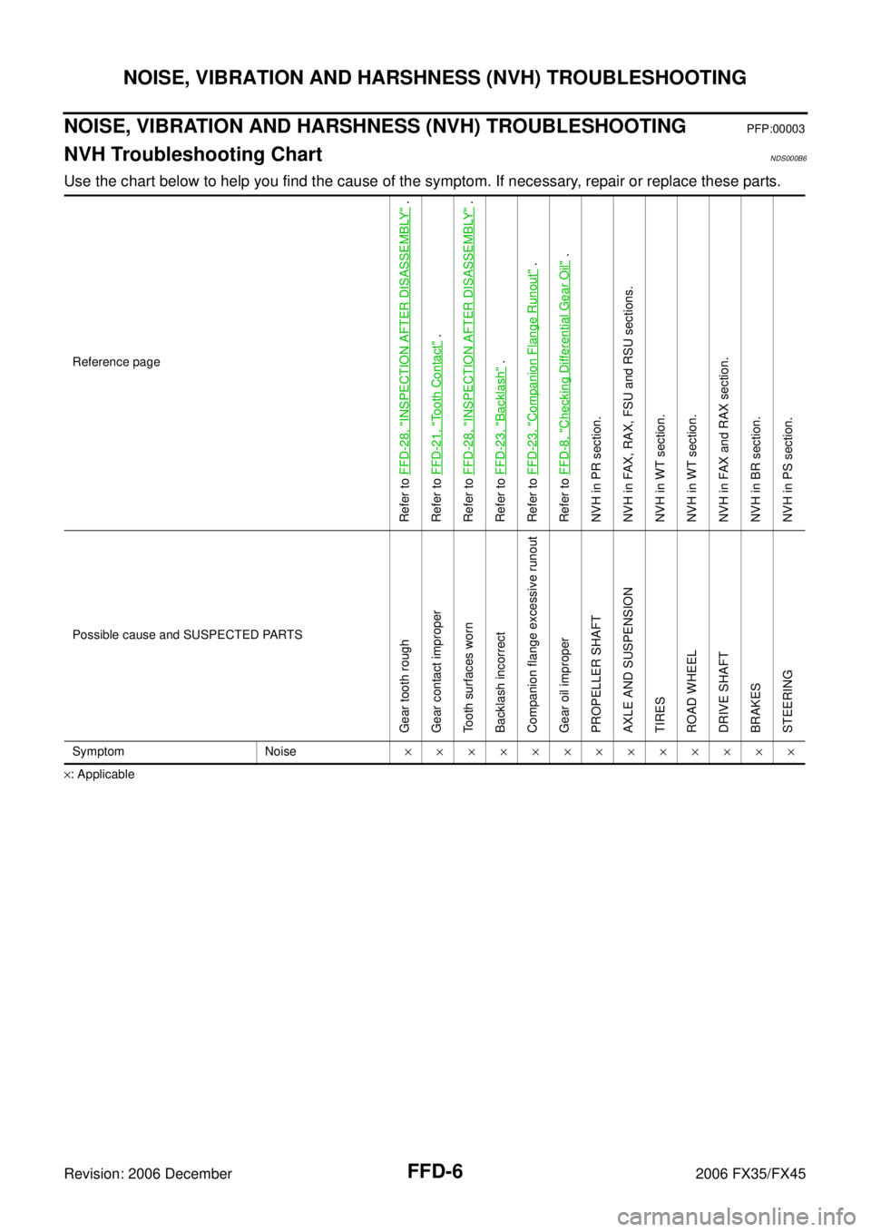
NOISE, VIBRATION AND HARSHNESS (NVH) TROUBLESHOOTINGPFP:00003
NVH Troubleshooting ChartNDS000B6
Use the chart below to help you find the cause of the symptom. If necessary, repair or replace these parts.
× : Applicable Reference page
Refer to
FFD-28, "
INSPECTION AFTER DISASSEMBLY
" .
Refer to FFD-21, "
Tooth Contact
" .
Refer to FFD-28, "
INSPECTION AFTER DISASSEMBLY
" .
Refer to FFD-23, "
Backlash
" .
Refer to FFD-23, "
Companion Flange Runout
" .
Refer to FFD-8, "
Checking Differential Gear Oil
" .
NVH in PR section.
NVH in FAX, RAX, FSU and RSU sections.
NVH in WT section.
NVH in WT section.
NVH in FAX and RAX section.
NVH in BR section.
NVH in PS section.
Possible cause and SUSPECTED PARTS
Gear tooth rough
Gear contact improper
Tooth surfaces worn
Backlash incorrect
Companion flange excessive runout
Gear oil improper
PROPELLER SHAFT
AXLE AND SUSPENSION
TIRES
ROAD WHEEL
DRIVE SHAFT
BRAKES
STEERING
Symptom Noise ×××××××××××××
Page 3168 of 4462
FSU-2
PRECAUTIONS
Revision: 2006 December 2006 FX35/FX45
PRECAUTIONSPFP:00001
CautionNES000FK
�When installing rubber bushings, final tightening must be carried out under unladen conditions with tires
on ground. Oil will shorten the life of rubber bushings. Be sure to wipe off any spilled oil.
�Unladen conditions mean that fuel, engine coolant and lubricant are full. Spare tire, jack, hand tools and
mats are in designated positions.
�After servicing suspension parts, be sure to check wheel alignment.
�Caulking nuts are not reusable. Always use new ones when installing. Since new caulking nuts are pre-
oiled, tighten as they are.
�Avoid burden to front cross bar.
Page 3171 of 4462
NOISE, VIBRATION AND HARSHNESS (NVH) TROUBLESHOOTING FSU-5
C
D
F
G H
I
J
K L
M A
B
FSU
Revision: 2006 December 2006 FX35/FX45
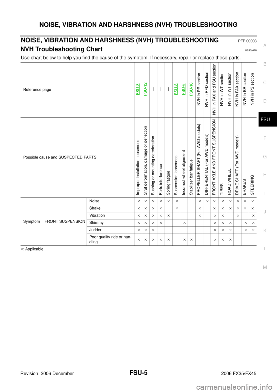
NOISE, VIBRATION AND HARSHNESS (NVH) TROUBLESHOOTINGPFP:00003
NVH Troubleshooting ChartNES000FN
Use chart below to help you find the cause of the symptom. If necessary, repair or replace these parts.
× : Applicable Reference page
FSU-8FSU-12
—
—
—
FSU-8FSU-6FSU-16
NVH in PR section
NVH in RFD section
NVH in FAX and FSU section
NVH in WT section
NVH in WT section
NVH in FAX section NVH in BR section NVH in PS section
Possible cause and SUSPECTED PARTS
Improper installation, looseness
Strut deformation, damage or deflection
Bushing or mounting deterioration
Parts interference
Spring fatigue
Suspension looseness
Incorrect wheel alignment
Stabilizer bar fatigue
PROPELLER SHAFT (For AWD models)
DIFFERENTIAL (For AWD models)
FRONT AXLE AND FRONT SUSPENSION
TIRES
ROAD WHEEL
DRIVE SHAFT (For AWD models)
BRAKES
STEERING
Symptom FRONT SUSPENSION Noise
××××× × ××× ×××××
Shake ×××× × × × ×××××
Vibration ××××× × ×× × ×
Shimmy ×××× × ××× ××
Judder ××× ××× ××
Poor quality ride or han-
dling ××××× ×× ×××
Page 3172 of 4462
FSU-6
FRONT SUSPENSION ASSEMBLY
Revision: 2006 December 2006 FX35/FX45
FRONT SUSPENSION ASSEMBLYPFP:54010
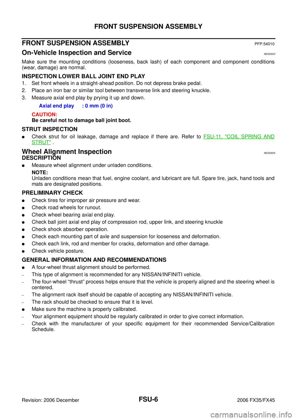
On-Vehicle Inspection and ServiceNES000I3
Make sure the mounting conditions (looseness, back lash) of each component and component conditions
(wear, damage) are normal.
INSPECTION LOWER BALL JOINT END PLAY
1. Set front wheels in a straight-ahead position. Do not depress brake pedal.
2. Place an iron bar or similar tool between transverse link and steering knuckle.
3. Measure axial end play by prying it up and down.
CAUTION:
Be careful not to damage ball joint boot.
STRUT INSPECTION
�Check strut for oil leakage, damage and replace if there are. Refer to FSU-11, "COIL SPRING AND
STRUT" .
Wheel Alignment InspectionNES000I4
DESCRIPTION
�Measure wheel alignment under unladen conditions.
NOTE:
Unladen conditions mean that fuel, engine coolant, and lubricant are full. Spare tire, jack, hand tools and
mats are designated positions.
PRELIMINARY CHECK
�Check tires for improper air pressure and wear.
�Check road wheels for runout.
�Check wheel bearing axial end play.
�Check ball joint axial end play of compression rod, upper link, and steering knuckle
�Check shock absorber operation.
�Check each mounting part of axle and suspension for looseness and deformation.
�Check each link, rod and member for cracks, deformation and other damage.
�Check vehicle posture.
GENERAL INFORMATION AND RECOMMENDATIONS
�A four-wheel thrust alignment should be performed.
–This type of alignment is recommended for any NISSAN/INFINITI vehicle.
–The four-wheel “thrust” process helps ensure that the vehicle is properly aligned and the steering wheel is
centered.
–The alignment rack itself should be capable of accepting any NISSAN/INFINITI vehicle.
–The rack should be checked to ensure that it is level.
�Make sure the machine is properly calibrated.
–Your alignment equipment should be regularly calibrated in order to give correct information.
–Check with the manufacturer of your specific equipment for their recommended Service/Calibration
Schedule. Axial end play : 0 mm (0 in)