Page 4368 of 4462

WT-6
NOISE, VIBRATION AND HARSHNESS (NVH) TROUBLESHOOTING
Revision: 2006 December 2006 FX35/FX45
NOISE, VIBRATION AND HARSHNESS (NVH) TROUBLESHOOTINGPFP:00003
NVH Troubleshooting ChartNES000GL
Use the chart below to help you find the cause of the symptom. If necessary, repair or replace these parts.
× : Applicable
Reference page
FAX-4
,
FAX-10
, FSU-6
WT-7—
—
—
—
—
—
NVH in PR section
NVH in RFD section
NVH in FAX and FSU section
NVH in RAX and RSU section
Refer to TIRES in this chart.
Refer to ROAD WHEEL in this chart. NVH in FAX, RAX sectionNVH in BR section NVH in PS section
Possible cause and SUSPECTED PARTS
Improper installation, looseness
Out-of-round
Imbalance
Incorrect tire pressure
Uneven tire wear
Deformation or damage
Non-uniformity
Incorrect tire size
PROPELLER SHAFT
DIFFERENTIAL
FRONT AXLE AND FRONT SUSPENSION
REAR AXLE AND REAR SUSPENSION
TIRES
ROAD WHEEL
DRIVE SHAFT
BRAKE
STEERING
Symptom TIRES Noise
× ×××××× ×××× ××××
Shake × ××××× ×× ×× ××××
Vibration ×××××××
Shimmy × ××××××× ×× × ××
Judder × ××××× × ×× × ××
Poor quality ride
or handling × ××××× × ×× ×
ROAD WHEEL Noise
× ×× × ××××× ×××
Shake × ×× × × ××× ×××
Shimmy, Judder × ×× × ××× ××
Poor quality ride
or handling × ×× × ×××
Page 4369 of 4462
ROAD WHEEL WT-7
C
D
F
G H
I
J
K L
M A
B
WT
Revision: 2006 December 2006 FX35/FX45
ROAD WHEELPFP:40300
InspectionNES000GM
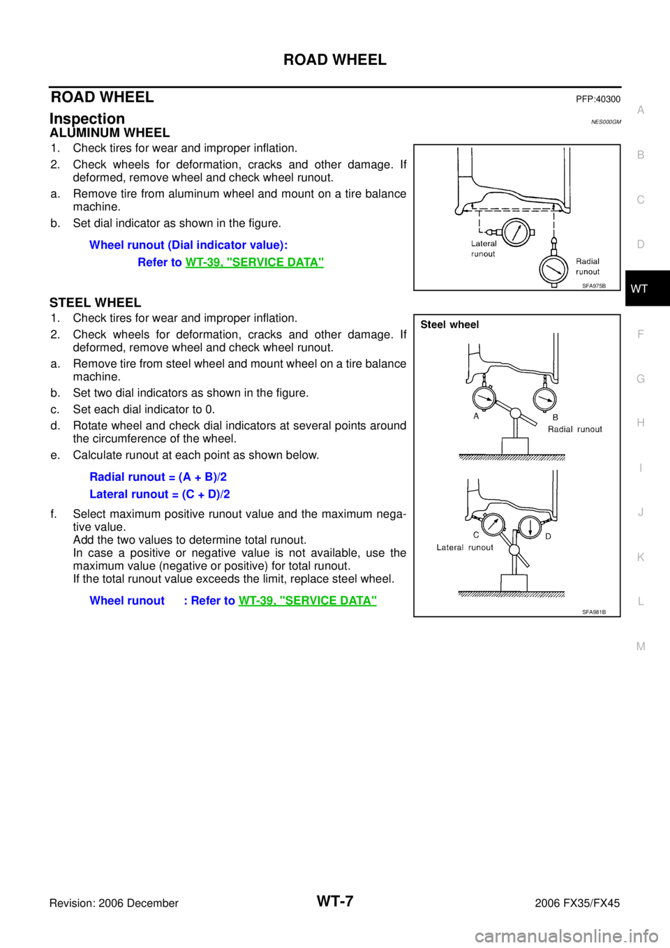
ALUMINUM WHEEL
1. Check tires for wear and improper inflation.
2. Check wheels for deformation, cracks and other damage. If deformed, remove wheel and check wheel runout.
a. Remove tire from aluminum wheel and mount on a tire balance machine.
b. Set dial indicator as shown in the figure.
STEEL WHEEL
1. Check tires for wear and improper inflation.
2. Check wheels for deformation, cracks and other damage. If deformed, remove wheel and check wheel runout.
a. Remove tire from steel wheel and mount wheel on a tire balance machine.
b. Set two dial indicators as shown in the figure.
c. Set each dial indicator to 0.
d. Rotate wheel and check dial indicators at several points around the circumference of the wheel.
e. Calculate runout at each point as shown below.
f. Select maximum positive runout value and the maximum nega- tive value.
Add the two values to determine total runout.
In case a positive or negative value is not available, use the
maximum value (negative or positive) for total runout.
If the total runout value exceeds the limit, replace steel wheel. Wheel runout (Dial indicator value):
Refer to WT-39, "
SERVICE DATA"
SFA975B
Radial runout = (A + B)/2
Lateral runout = (C + D)/2
Wheel runout : Refer to WT-39, "
SERVICE DATA"SFA981B
Page 4371 of 4462
ROAD WHEEL TIRE ASSEMBLY WT-9
C
D
F
G H
I
J
K L
M A
B
WT
Revision: 2006 December 2006 FX35/FX45
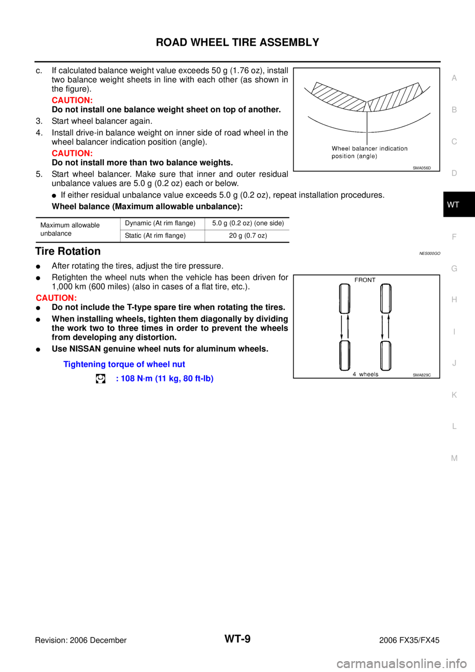
c. If calculated balance weight value exceeds 50 g (1.76 oz), install two balance weight sheets in line with each other (as shown in
the figure).
CAUTION:
Do not install one balance weight sheet on top of another.
3. Start wheel balancer again.
4. Install drive-in balance weight on inner side of road wheel in the wheel balancer indication position (angle).
CAUTION:
Do not install more than two balance weights.
5. Start wheel balancer. Make sure that inner and outer residual unbalance values are 5.0 g (0.2 oz) each or below.
�If either residual unbalance value exceeds 5.0 g (0.2 oz), repeat installation procedures.
Wheel balance (Maximum allowable unbalance):
Tire RotationNES000GO
�After rotating the tires, adjust the tire pressure.
�Retighten the wheel nuts when the vehicle has been driven for
1,000 km (600 miles) (also in cases of a flat tire, etc.).
CAUTION:
�Do not include the T-type spare tire when rotating the tires.
�When installing wheels, tighten them diagonally by dividing
the work two to three times in order to prevent the wheels
from developing any distortion.
�Use NISSAN genuine wheel nuts for aluminum wheels.
Maximum allowable
unbalance Dynamic (At rim flange) 5.0 g (0.2 oz) (one side)
Static (At rim flange) 20 g (0.7 oz)
SMA056D
Tightening torque of wheel nut : 108 N·m (11 kg, 80 ft-lb)
SMA829C
Page 4381 of 4462
TROUBLE DIAGNOSES WT-19
C
D
F
G H
I
J
K L
M A
B
WT
Revision: 2006 December 2006 FX35/FX45
ID REGISTRATION WITHOUT ACTIVATION TOOL
This procedure must be done after replacement of a transmitter or BCM.
CAUTION:
If CONSULT-II is used with no connection of CONSULT-II CONVERTER, malfunction might be detected
during self-diagnosis depending on control unit which performs CAN communication.
1. With the ignition switch OFF, connect CONSULT-II and CONSULT-II CONVERTER to the data link con- nector, then turn the ignition switch ON.
2. Select “START (NISSAN BASED VHCL)”.
3. Select “BCM” on “SELECT SYSTEM” screen. NOTE:
If “BCM” is not indicated, go to GI-39, "
CONSULT-II Data Link Connector (DLC) Circuit" .
4. Select “AIR PRESSURE MONITOR” on “SELECT WORK ITEM” screen.
5. Select “WORK SUPPORT” on “SELECT DIAG MODE” screen, and select “ID REGIST”.
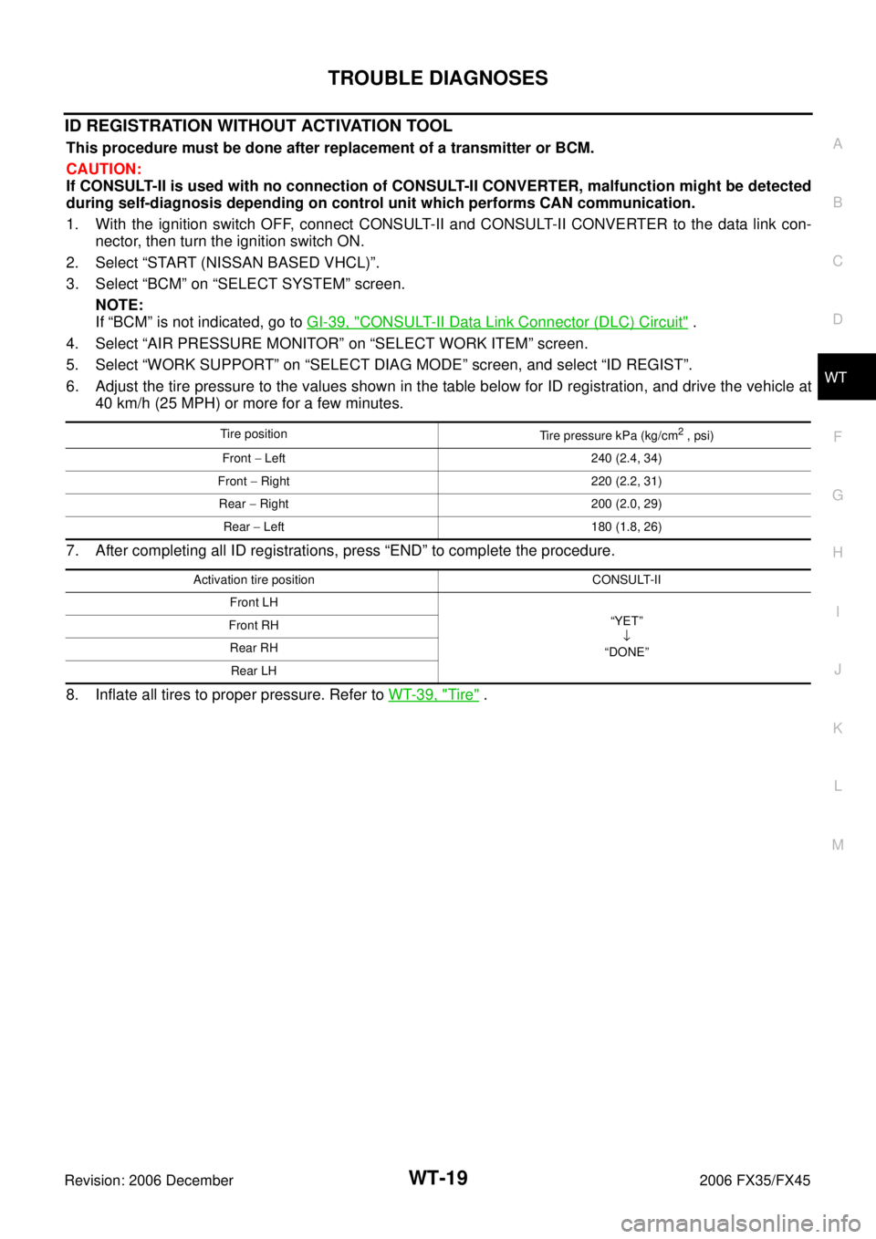
6. Adjust the tire pressure to the values shown in the table below for ID registration, and drive the vehicle at 40 km/h (25 MPH) or more for a few minutes.
7. After completing all ID registrations, press “END” to complete the procedure.
8. Inflate all tires to proper pressure. Refer to WT-39, "
Tire" .
Tire position
Tire pressure kPa (kg/cm2 , psi)
Front − Left 240 (2.4, 34)
Front − Right 220 (2.2, 31)
Rear − Right 200 (2.0, 29)
Rear − Left 180 (1.8, 26)
Activation tire position CONSULT-II
Front LH “YET” ↓
“DONE”
Front RH
Rear RHRear LH
Page 4393 of 4462
TROUBLE DIAGNOSIS FOR SELF-DIAGNOSTIC ITEMS WT-31
C
D
F
G H
I
J
K L
M A
B
WT
Revision: 2006 December 2006 FX35/FX45
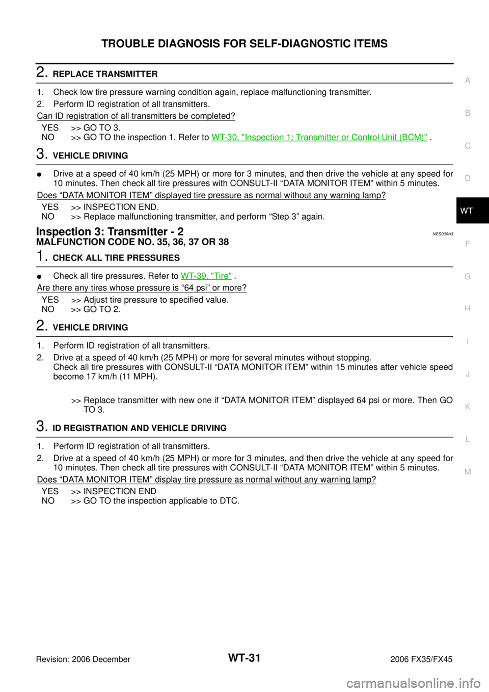
2. REPLACE TRANSMITTER
1. Check low tire pressure warning condition again, replace malfunctioning transmitter.
2. Perform ID registration of all transmitters.
Can ID registration of all transmitters be completed?
YES >> GO TO 3.
NO >> GO TO the inspection 1. Refer to WT-30, "
Inspection 1: Transmitter or Control Unit (BCM)" .
3. VEHICLE DRIVING
�Drive at a speed of 40 km/h (25 MPH) or more for 3 minutes, and then drive the vehicle at any speed for
10 minutes. Then check all tire pressures with CONSULT-II “DATA MONITOR ITEM” within 5 minutes.
Does
“DATA MONITOR ITEM” displayed tire pressure as normal without any warning lamp?
YES >> INSPECTION END.
NO >> Replace malfunctioning transmitter, and perform “Step 3” again.
Inspection 3: Transmitter - 2NES000H3
MALFUNCTION CODE NO. 35, 36, 37 OR 38
1. CHECK ALL TIRE PRESSURES
�Check all tire pressures. Refer to WT-39, "Tire" .
Are there any tires whose pressure is
“64 psi” or more?
YES >> Adjust tire pressure to specified value.
NO >> GO TO 2.
2. VEHICLE DRIVING
1. Perform ID registration of all transmitters.
2. Drive at a speed of 40 km/h (25 MPH) or more for several minutes without stopping. Check all tire pressures with CONSULT-II “DATA MONITOR ITEM” within 15 minutes after vehicle speed
become 17 km/h (11 MPH).
>> Replace transmitter with new one if “DATA MONITOR ITEM” displayed 64 psi or more. Then GO TO 3.
3. ID REGISTRATION AND VEHICLE DRIVING
1. Perform ID registration of all transmitters.
2. Drive at a speed of 40 km/h (25 MPH) or more for 3 minutes, and then drive the vehicle at any speed for 10 minutes. Then check all tire pressures with CONSULT-II “DATA MONITOR ITEM” within 5 minutes.
Does
“DATA MONITOR ITEM” display tire pressure as normal without any warning lamp?
YES >> INSPECTION END
NO >> GO TO the inspection applicable to DTC.