Page 520 of 4462
ATC-74
TROUBLE DIAGNOSIS
Revision: 2006 December 2006 FX35/FX45
Intake Door Motor CircuitNJS000E7
SYMPTOM
�Intake door does not change.
�Intake door motor does not operate normally.
INSPECTION FLOW
*1 AT C - 5 3 , "FUNCTION CONFIRMA-
TION PROCEDURE", see No. 4 to 6. *2
ATC-103, "
Ambient Sensor Circuit"*3 ATC-106, "In-vehicle Sensor Circuit"
*4 ATC-109, "Sunload Sensor Circuit"*5AT C - 7 1 , "Air Mix Door Motor Circuit"*6 AT C - 5 3 , "FUNCTION CONFIRMA-
TION PROCEDURE", see No. 13.
*7 AT C - 6 4 , "
LAN System Circuit"*8ATC-123, "INTAKE DOOR MOTOR"*9 AT C - 6 0 , "Operational Check"
*10 AT C - 4 1 , "SYMPTOM TABLE"*11AT C - 11 2 , "Intake Sensor Circuit"
SJIA1587E
Page 521 of 4462
TROUBLE DIAGNOSIS ATC-75
C
D E
F
G H
I
K L
M A
B
AT C
Revision: 2006 December 2006 FX35/FX45
SYSTEM DESCRIPTION
Component Parts
Intake door control system components are:
�Unified meter and A/C amp.
�Intake door motor (LCU)
�A/C LAN system (PBR built-in mode door motor, air mix door motor and intake door motor)
�In-vehicle sensor
�Ambient sensor
�Sunload sensor
�Intake sensor
System Operation
The intake door control determines intake door position based on the ambient temperature, the intake air tem-
perature and the in-vehicle temperature. When the DEF, or OFF switches are pressed or A/C switch is OFF,
the unified meter and A/C amp. sets the intake door at the FRESH position.
Intake Door Control Specification
SJIA1588E
RJIA1787E
Page 524 of 4462
ATC-78
TROUBLE DIAGNOSIS
Revision: 2006 December 2006 FX35/FX45
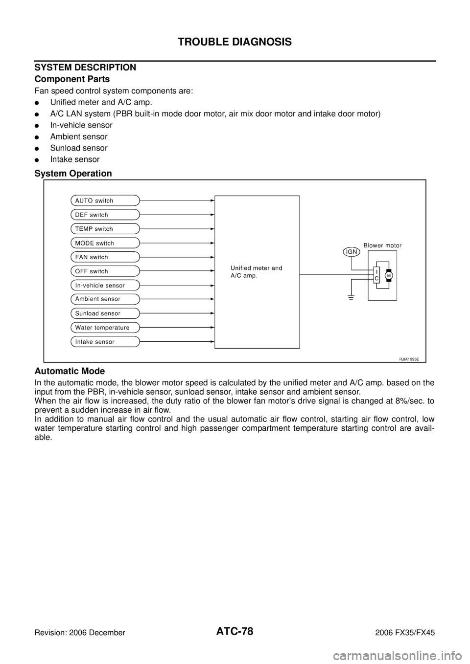
SYSTEM DESCRIPTION
Component Parts
Fan speed control system components are:
�Unified meter and A/C amp.
�A/C LAN system (PBR built-in mode door motor, air mix door motor and intake door motor)
�In-vehicle sensor
�Ambient sensor
�Sunload sensor
�Intake sensor
System Operation
Automatic Mode
In the automatic mode, the blower motor speed is calculated by the unified meter and A/C amp. based on the
input from the PBR, in-vehicle sensor, sunload sensor, intake sensor and ambient sensor.
When the air flow is increased, the duty ratio of the blower fan motor’s drive signal is changed at 8%/sec. to
prevent a sudden increase in air flow.
In addition to manual air flow control and the usual automatic air flow control, starting air flow control, low
water temperature starting control and high passenger compartment temperature starting control are avail-
able.
RJIA1995E
Page 529 of 4462
TROUBLE DIAGNOSIS ATC-83
C
D E
F
G H
I
K L
M A
B
AT C
Revision: 2006 December 2006 FX35/FX45
SYSTEM DESCRIPTION
Unified meter and A/C amp. controls compressor operation by ambient temperature, intake air temperature
and signal from ECM.
Low Temperature Protection Control
Unified meter and A/C amp. will turn the compressor ON or OFF as determined by a signal detected by ambi-
ent sensor and intake sensor.
When ambient temperature is higher than −2 °C (28 °F), the compres-
sor turns ON. The compressor turns OFF when ambient temperature
is lower than −5 °C (23 °F).
When intake air temperature is higher than 1 °C (34 °F), the compres-
sor turns ON. The compressor turns OFF when intake air tempera-
ture is lower than −5°C (23 °F).
DIAGNOSIS PROCEDURE FOR MAGNET CLUTCH
SYMPTOM: Magnet clutch does not engage when A/C switch is ON.
RHA094GB
SJIA0267E
SJIA1608E
Page 532 of 4462
ATC-86
TROUBLE DIAGNOSIS
Revision: 2006 December 2006 FX35/FX45
7. CHECK VOLTAGE FOR UNIFIED METER AND A/C AMP. (COMPRESSOR ON SIGNAL)
1. Reconnect BCM connector and unified meter and A/C amp. connector.
2. Turn ignition switch ON.
3. Check voltage between unified meter and A/C amp. harness connector M57 terminal 42 and ground using an oscilloscope.
OK or NG
OK >> GO TO 8.
NG-1 >> If the voltage is approx. 5 V when A/C switch is ON: Replace unified meter and A/C amp.
NG-2 >> If the voltage is approx. 0 V when A/C switch is OFF: Replace BCM.
RJIA2007E
Terminals
Condition Voltage
(+)
( − )
Unified meter
and A/C amp. connector Terminal
No.
M57 42 Ground A/C switch: ON
(Blower motor operates.) Approx. 0 V
OFF switch: ON
(A/C system: OFF)
SJIA1423J
Page 534 of 4462

1. Reconnect BCM connector and unified meter and A/C amp. connector")
ATC-88
TROUBLE DIAGNOSIS
Revision: 2006 December 2006 FX35/FX45
11 . CHECK VOLTAGE FOR UNIFIED METER AND A/C AMP. (FAN ON SIGNAL)
1. Reconnect BCM connector and unified meter and A/C amp. connector.
2. Turn ignition switch ON.
3. Check voltage between unified meter and A/C amp. harness connector M57 terminal 57 and ground using an oscilloscope.
OK or NG
OK >> GO TO 12.
NG-1 >> If the voltage is approx. 5 V when blower motor is ON: Replace unified meter and A/C amp.
NG-2 >> If the voltage is approx. 0 V when blower motor is OFF: Replace BCM. Refer to BCS-15,
"Removal and Installation of BCM" .
12. CHECK CAN COMMUNICATION
Check CAN communication. Refer to BCS-14, "
CAN Communication Inspection Using CONSULT-II (Self-
Diagnosis)" .
�BCM – ECM
�ECM – IPDM E/R
�ECM – Unified meter and A/C amp.
OK or NG
OK >> Replace ECM
NG >> Repair or replace malfunctioning part(s).
RJIA2010E
Terminals
Condition Voltage
(+)
(-)
Unified meter
and A/C amp. connector Terminal No.
M57 57 Ground A/C switch: ON
(Blower motor operates.) Approx. 0 V
OFF switch: ON
(A/C system: OFF)
SJIA1474J
Page 537 of 4462
TROUBLE DIAGNOSIS ATC-91
C
D E
F
G H
I
K L
M A
B
AT C
Revision: 2006 December 2006 FX35/FX45
*1 ATC-53, "FUNCTION CONFIRMA-
TION PROCEDURE", see No. 4 to 6. *2
ATC-71, "
Air Mix Door Motor Circuit"*3ATC-94, "Test Reading"
*4 ATC-58, "AUXILIARY MECHA-
NISM: TEMPERATURE SETTING
TRIMMER"
*5ATC-53, "FUNCTION CONFIRMA-
TION PROCEDURE", see No. 13. *6
ATC-64, "
LAN System Circuit"
*7 ATC-77, "Blower Motor Circuit"*8ATC-82, "Magnet Clutch Circuit"*9ATC-92, "PERFORMANCE TEST
DIAGNOSIS"
*10 ATC-60, "Operational Check"*11AT C - 7 , "CONTAMINATED REFRIG-
ERANT"
*12EM-15, "Checking Drive Belts"
(VQ35DE) or EM-174, "
Checking
Drive Belts" (VK45DE)
*13 EC-497, "
SYSTEM DESCRIPTION"
(VQ35DE) or EC-1171, "
SYSTEM
DESCRIPTION" (VK45DE)
Page 540 of 4462

ATC-94
TROUBLE DIAGNOSIS
Revision: 2006 December 2006 FX35/FX45
PERFORMANCE CHART
Test Condition
Testing must be performed as follows:
Test Reading
Recirculating-to-discharge Air Temperature Table
Ambient Air Temperature-to-operating Pressure Table
Vehicle condition Indoors or in the shade (in a well-ventilated place)
Doors Closed
Door windows Open
Hood Open
TEMP. Max. COLD
Mode switch (Ventilation) set
Intake switch (Recirculation) set
Fan (blower) speed Max. speed set
Engine speed Idle speed
Operate the air conditioning system for 10 minutes before taking measurements.
Inside air (Recirculating air) at blower assembly inlet Discharge air temperature at center ventilator
° C ( °F)
Relative humidity
% Air temperature
° C ( °F)
50 - 60 20 (68) 11.2 - 13.2 (52 - 56)
25 (77) 12.2 - 14.8 (54 - 59)
30 (86) 15.5 - 18.6 (60 - 65)
35 (95) 21.0 - 24.5 (70 - 76)
40 (104) 28.7 - 32.6 (84 - 91)
60 - 70 20 (68) 13.2 - 15.2 (56 - 59)
25 (77) 14.8 - 17.3 (59 - 63)
30 (86) 18.6 - 21.6 (65 - 71)
35 (95) 24.5 - 28.0 (76 - 82)
40 (104) 32.6 - 36.5 (91 - 98)
Ambient air High-pressure (Discharge side)
kPa (kg/cm
2 , psi) Low-pressure (Suction side)
kPa (kg/cm2 , psi)
Relative humidity
% Air temperature
° C ( °F)
50 - 70 20 (68)
961 - 1,167
(9.8 - 11.9, 139 - 169) 216 - 265
(2.2 - 2.7, 31 - 38)
25 (77) 1,108 - 1,353
(11.3 - 13.8, 161 - 196) 230 - 281
(2.3 - 2.9, 33 - 41)
30 (86) 1,275 - 1,549
(13.0 - 15.8, 185 - 225) 261 - 320
(2.7 - 3.3, 38 - 46)
35 (95) 1,549 - 1,893
(15.8 - 19.3, 225 - 274) 297 - 364
(3.0 - 3.7, 43 - 53)
40 (104) 1,814 - 2,216
(18.5 - 22.6, 263 - 321) 357 - 435
(3.6 - 4.4, 52 - 63)


1. Reconnect BCM connector and unified meter and A/C amp. conne")
