Page 1355 of 4462
LANE DEPARTURE WARNING SYSTEM DI-105
C
D E
F
G H
I
J
L
M A
B
DI
Revision: 2006 December 2006 FX35/FX45
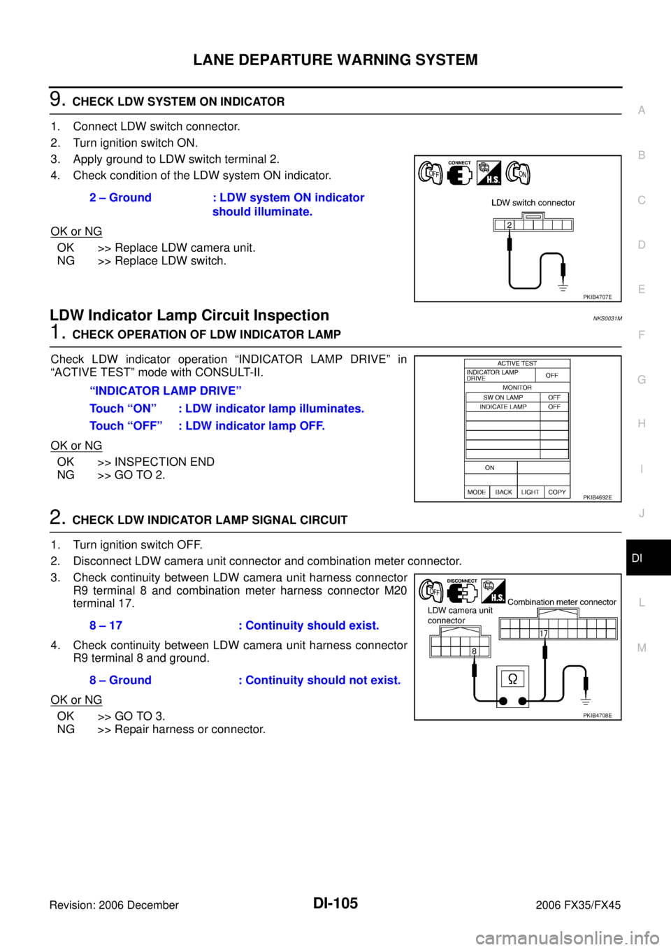
9. CHECK LDW SYSTEM ON INDICATOR
1. Connect LDW switch connector.
2. Turn ignition switch ON.
3. Apply ground to LDW switch terminal 2.
4. Check condition of the LDW system ON indicator.
OK or NG
OK >> Replace LDW camera unit.
NG >> Replace LDW switch.
LDW Indicator Lamp Circuit InspectionNKS0031M
1. CHECK OPERATION OF LDW INDICATOR LAMP
Check LDW indicator operation “INDICATOR LAMP DRIVE” in
“ACTIVE TEST” mode with CONSULT-II.
OK or NG
OK >> INSPECTION END
NG >> GO TO 2.
2. CHECK LDW INDICATOR LAMP SIGNAL CIRCUIT
1. Turn ignition switch OFF.
2. Disconnect LDW camera unit connector and combination meter connector.
3. Check continuity between LDW camera unit harness connector R9 terminal 8 and combination meter harness connector M20
terminal 17.
4. Check continuity between LDW camera unit harness connector R9 terminal 8 and ground.
OK or NG
OK >> GO TO 3.
NG >> Repair harness or connector. 2 – Ground : LDW system ON indicator
should illuminate.
PKIB4707E
“INDICATOR LAMP DRIVE”
Touch “ON” : LDW indicator lamp illuminates.
Touch “OFF” : LDW indicator lamp OFF.
PKIB4692E
8 – 17 : Continuity should exist.
8 – Ground : Continuity should not exist.
PKIB4708E
Page 1356 of 4462
DI-106
LANE DEPARTURE WARNING SYSTEM
Revision: 2006 December 2006 FX35/FX45
3. CHECK LDW INDICATOR LAMP OPERATION
1. Connect combination meter connector.
2. Turn ignition switch ON.
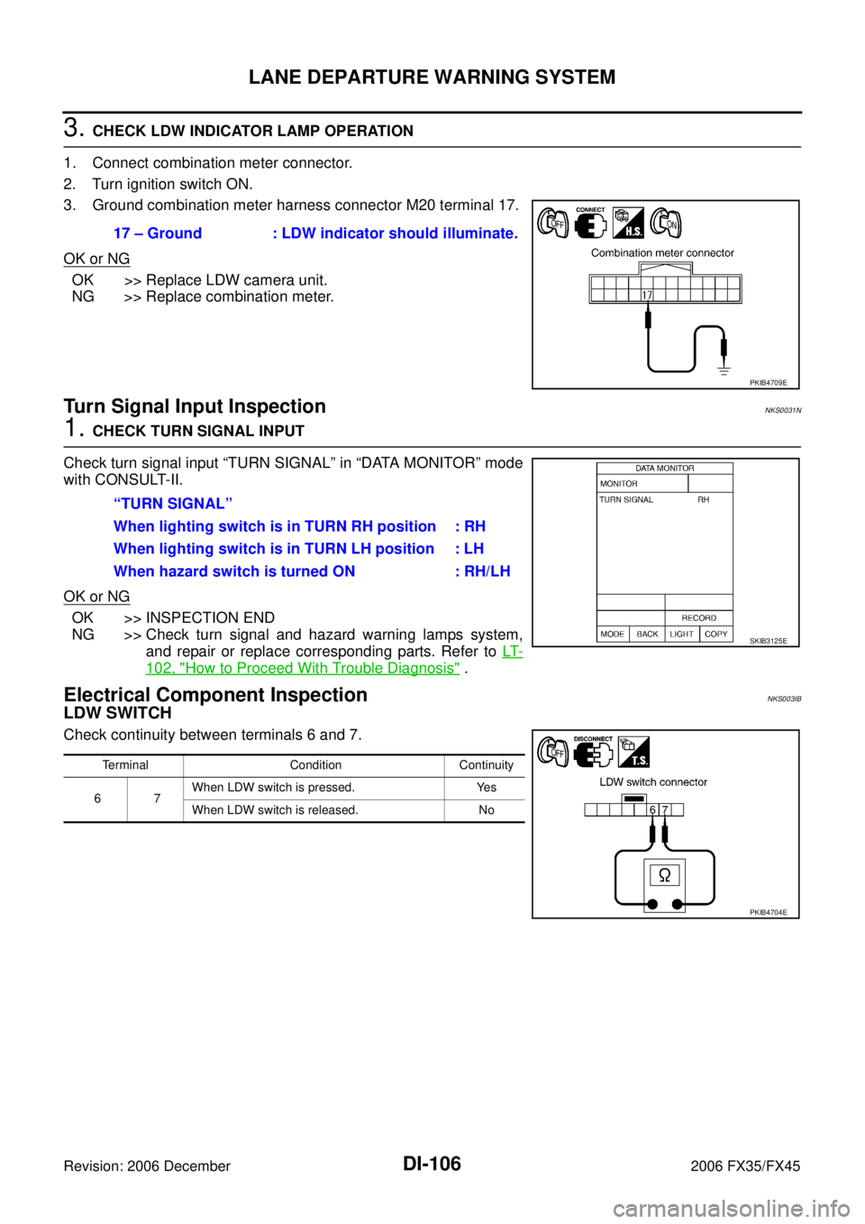
3. Ground combination meter harness connector M20 terminal 17.
OK or NG
OK >> Replace LDW camera unit.
NG >> Replace combination meter.
Turn Signal Input InspectionNKS0031N
1. CHECK TURN SIGNAL INPUT
Check turn signal input “TURN SIGNAL” in “DATA MONITOR” mode
with CONSULT-II.
OK or NG
OK >> INSPECTION END
NG >> Check turn signal and hazard warning lamps system,
and repair or replace corresponding parts. Refer to LT-
102, "How to Proceed With Trouble Diagnosis" .
Electrical Component InspectionNKS003IB
LDW SWITCH
Check continuity between terminals 6 and 7. 17 – Ground : LDW indicator should illuminate.
PKIB4709E
“TURN SIGNAL”
When lighting switch is in TURN RH position : RH
When lighting switch is in TURN LH position : LH
When hazard switch is turned ON : RH/LH
SKIB3125E
Terminal Condition Continuity
67 When LDW switch is pressed. Yes
When LDW switch is released. No
PKIB4704E
Page 1377 of 4462
REAR VIEW MONITOR DI-127
C
D E
F
G H
I
J
L
M A
B
DI
Revision: 2006 December 2006 FX35/FX45
Rear View Is Not Displayed With The A/T Selector Lever In R-PositionNKS00321
1. BACK-UP LAMP INSPECTION
1. Turn ignition switch ON.
2. Shift A/T selector lever to R position.
Does back-up lamp illuminate?
YES >> GO TO 2.
NO >> Check back-up lamp system. Refer to LT- 1 3 1 , "
BACK-UP LAMP" in LT section.
2. CHECK REVERSE POSITION INPUT SIGNAL
With CONSULT-II
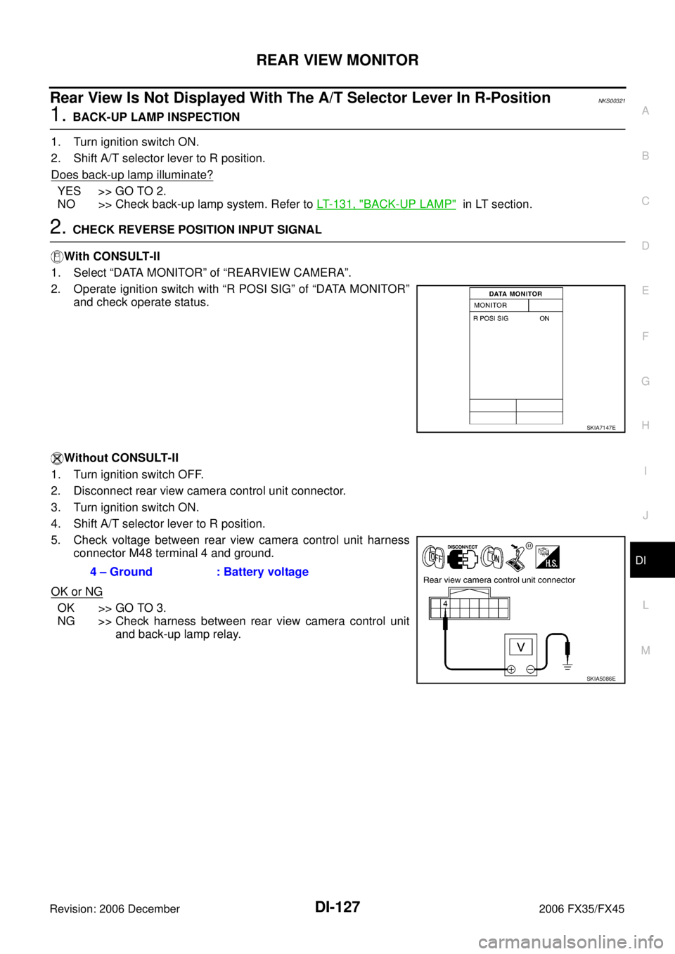
1. Select “DATA MONITOR” of “REARVIEW CAMERA”.
2. Operate ignition switch with “R POSI SIG” of “DATA MONITOR” and check operate status.
Without CONSULT-II
1. Turn ignition switch OFF.
2. Disconnect rear view camera control unit connector.
3. Turn ignition switch ON.
4. Shift A/T selector lever to R position.
5. Check voltage between rear view camera control unit harness connector M48 terminal 4 and ground.
OK or NG
OK >> GO TO 3.
NG >> Check harness between rear view camera control unit
and back-up lamp relay.
SKIA7147E
4 – Ground : Battery voltage
SKIA5086E
Page 1378 of 4462
DI-128
REAR VIEW MONITOR
Revision: 2006 December 2006 FX35/FX45
3. CHECK DISPLAY CONTROL UNIT OUTPUT SIGNAL
1. Turn ignition switch OFF.
2. Disconnect rear view camera control unit connector.
3. Turn ignition switch ON.
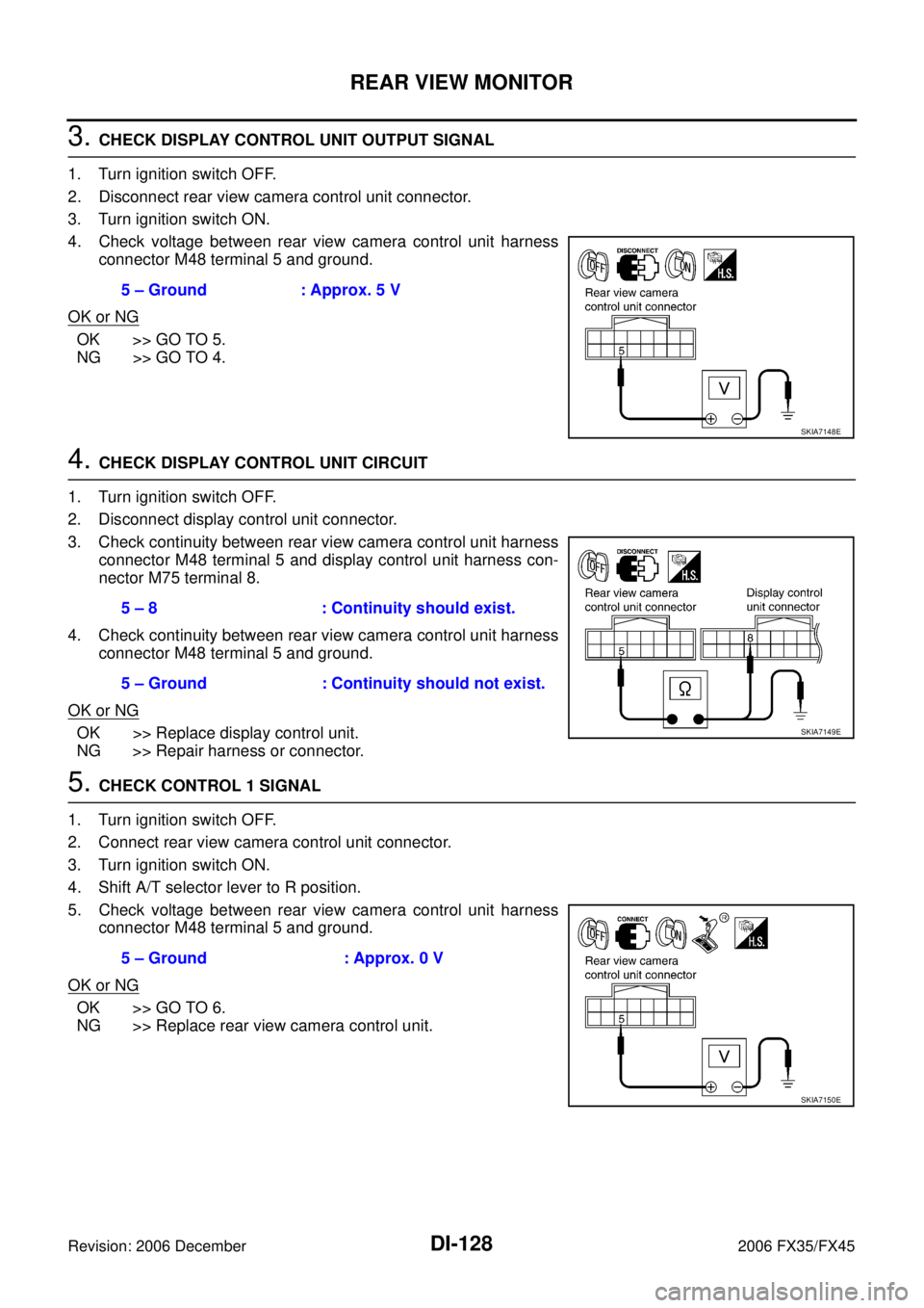
4. Check voltage between rear view camera control unit harness connector M48 terminal 5 and ground.
OK or NG
OK >> GO TO 5.
NG >> GO TO 4.
4. CHECK DISPLAY CONTROL UNIT CIRCUIT
1. Turn ignition switch OFF.
2. Disconnect display control unit connector.
3. Check continuity between rear view camera control unit harness connector M48 terminal 5 and display control unit harness con-
nector M75 terminal 8.
4. Check continuity between rear view camera control unit harness connector M48 terminal 5 and ground.
OK or NG
OK >> Replace display control unit.
NG >> Repair harness or connector.
5. CHECK CONTROL 1 SIGNAL
1. Turn ignition switch OFF.
2. Connect rear view camera control unit connector.
3. Turn ignition switch ON.
4. Shift A/T selector lever to R position.
5. Check voltage between rear view camera control unit harness connector M48 terminal 5 and ground.
OK or NG
OK >> GO TO 6.
NG >> Replace rear view camera control unit. 5 – Ground : Approx. 5 V
SKIA7148E
5 – 8 : Continuity should exist.
5 – Ground : Continuity should not exist.
SKIA7149E
5 – Ground : Approx. 0 V
SKIA7150E
Page 1380 of 4462
DI-130
REAR VIEW MONITOR
Revision: 2006 December 2006 FX35/FX45
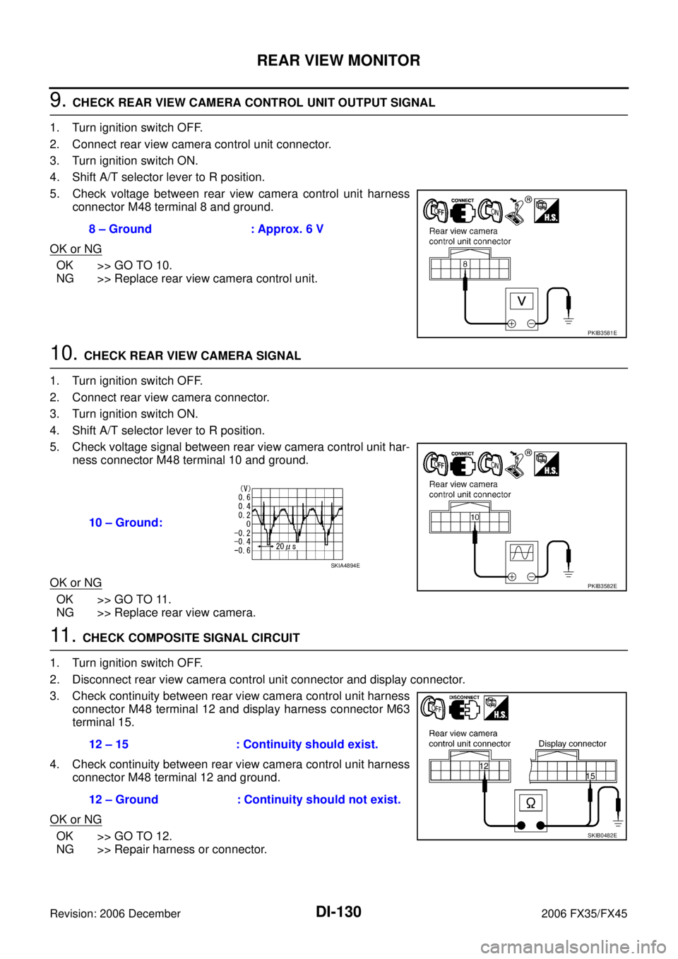
9. CHECK REAR VIEW CAMERA CONTROL UNIT OUTPUT SIGNAL
1. Turn ignition switch OFF.
2. Connect rear view camera control unit connector.
3. Turn ignition switch ON.
4. Shift A/T selector lever to R position.
5. Check voltage between rear view camera control unit harness connector M48 terminal 8 and ground.
OK or NG
OK >> GO TO 10.
NG >> Replace rear view camera control unit.
10. CHECK REAR VIEW CAMERA SIGNAL
1. Turn ignition switch OFF.
2. Connect rear view camera connector.
3. Turn ignition switch ON.
4. Shift A/T selector lever to R position.
5. Check voltage signal between rear view camera control unit har- ness connector M48 terminal 10 and ground.
OK or NG
OK >> GO TO 11.
NG >> Replace rear view camera.
11 . CHECK COMPOSITE SIGNAL CIRCUIT
1. Turn ignition switch OFF.
2. Disconnect rear view camera control unit connector and display connector.
3. Check continuity between rear view camera control unit harness connector M48 terminal 12 and display harness connector M63
terminal 15.
4. Check continuity between rear view camera control unit harness connector M48 terminal 12 and ground.
OK or NG
OK >> GO TO 12.
NG >> Repair harness or connector. 8 – Ground : Approx. 6 V
PKIB3581E
10 – Ground:
PKIB3582E
SKIA4894E
12 – 15 : Continuity should exist.
12 – Ground : Continuity should not exist.
SKIB0482E
Page 1381 of 4462
REAR VIEW MONITOR DI-131
C
D E
F
G H
I
J
L
M A
B
DI
Revision: 2006 December 2006 FX35/FX45
12. CHECK COMPOSITE SIGNAL GROUND CIRCUIT
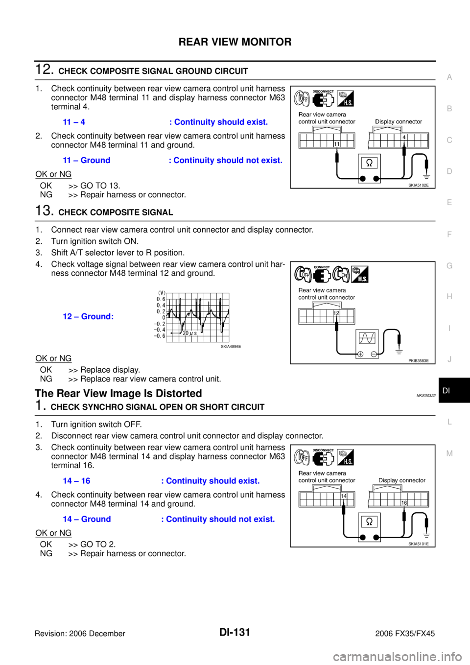
1. Check continuity between rear view camera control unit harness connector M48 terminal 11 and display harness connector M63
terminal 4.
2. Check continuity between rear view camera control unit harness connector M48 terminal 11 and ground.
OK or NG
OK >> GO TO 13.
NG >> Repair harness or connector.
13. CHECK COMPOSITE SIGNAL
1. Connect rear view camera control unit connector and display connector.
2. Turn ignition switch ON.
3. Shift A/T selector lever to R position.
4. Check voltage signal between rear view camera control unit har- ness connector M48 terminal 12 and ground.
OK or NG
OK >> Replace display.
NG >> Replace rear view camera control unit.
The Rear View Image Is DistortedNKS00322
1. CHECK SYNCHRO SIGNAL OPEN OR SHORT CIRCUIT
1. Turn ignition switch OFF.
2. Disconnect rear view camera control unit connector and display connector.
3. Check continuity between rear view camera control unit harness connector M48 terminal 14 and display harness connector M63
terminal 16.
4. Check continuity between rear view camera control unit harness connector M48 terminal 14 and ground.
OK or NG
OK >> GO TO 2.
NG >> Repair harness or connector. 11 – 4 : Continuity should exist.
11 – Ground : Continuity should not exist.
SKIA5102E
12 – Ground:
PKIB3583E
SKIA4896E
14 – 16 : Continuity should exist.
14 – Ground : Continuity should not exist.
SKIA5101E
Page 1382 of 4462
DI-132
REAR VIEW MONITOR
Revision: 2006 December 2006 FX35/FX45
2. CHECK COMPOSITE SIGNAL GROUND CIRCUIT
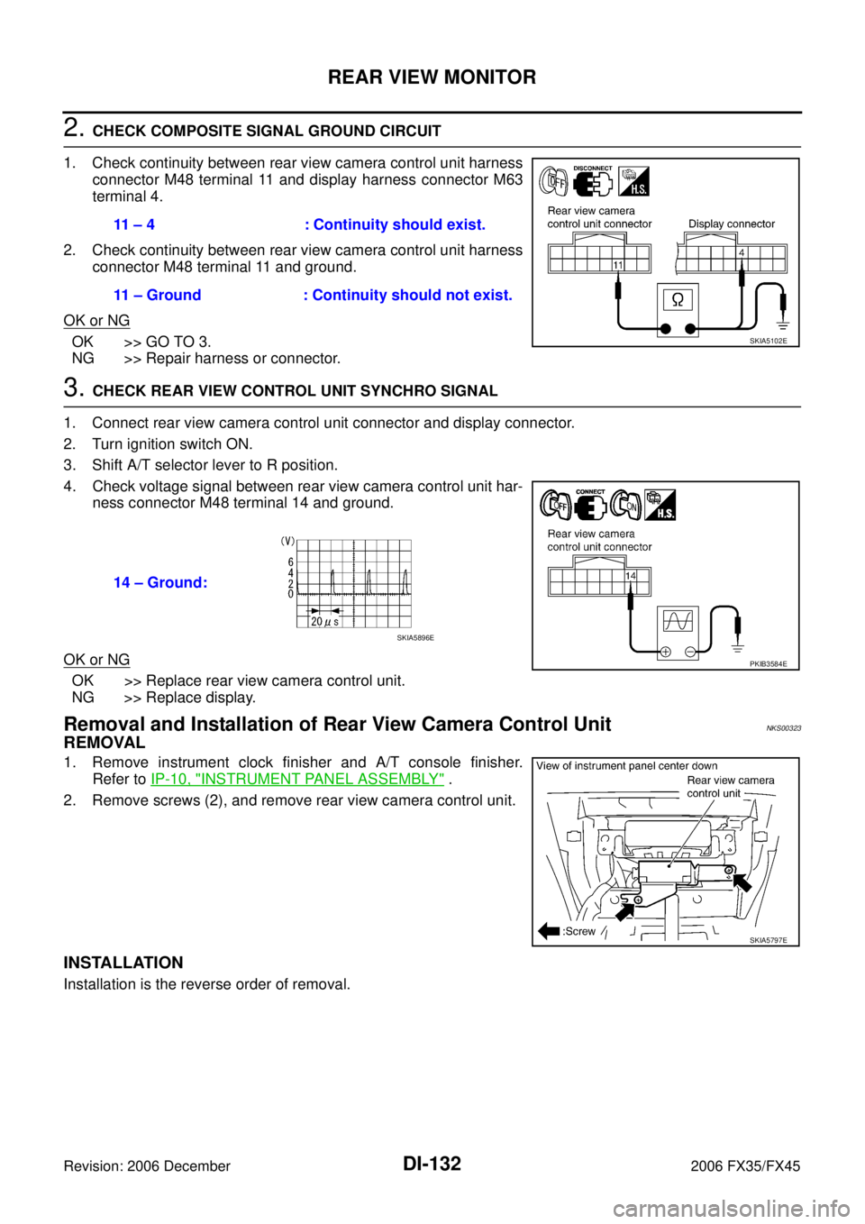
1. Check continuity between rear view camera control unit harness connector M48 terminal 11 and display harness connector M63
terminal 4.
2. Check continuity between rear view camera control unit harness connector M48 terminal 11 and ground.
OK or NG
OK >> GO TO 3.
NG >> Repair harness or connector.
3. CHECK REAR VIEW CONTROL UNIT SYNCHRO SIGNAL
1. Connect rear view camera control unit connector and display connector.
2. Turn ignition switch ON.
3. Shift A/T selector lever to R position.
4. Check voltage signal between rear view camera control unit har- ness connector M48 terminal 14 and ground.
OK or NG
OK >> Replace rear view camera control unit.
NG >> Replace display.
Removal and Installation of Rear View Camera Control UnitNKS00323
REMOVAL
1. Remove instrument clock finisher and A/T console finisher. Refer to IP-10, "
INSTRUMENT PANEL ASSEMBLY" .
2. Remove screws (2), and remove rear view camera control unit.
INSTALLATION
Installation is the reverse order of removal. 11 – 4 : Continuity should exist.
11 – Ground : Continuity should not exist.
SKIA5102E
14 – Ground:
PKIB3584E
SKIA5896E
SKIA5797E
Page 1419 of 4462
![INFINITI FX35 2006 Service Manual AIR CONDITIONING CUT CONTROL EC-35
[VQ35DE]
C
D E
F
G H
I
J
K L
M A
EC
Revision: 2006 December 2006 FX35/FX45
AIR CONDITIONING CUT CONTROLPFP:23710
Input/Output Signal ChartNBS003L5
*1: Th INFINITI FX35 2006 Service Manual AIR CONDITIONING CUT CONTROL EC-35
[VQ35DE]
C
D E
F
G H
I
J
K L
M A
EC
Revision: 2006 December 2006 FX35/FX45
AIR CONDITIONING CUT CONTROLPFP:23710
Input/Output Signal ChartNBS003L5
*1: Th](/manual-img/42/57019/w960_57019-1418.png)
AIR CONDITIONING CUT CONTROL EC-35
[VQ35DE]
C
D E
F
G H
I
J
K L
M A
EC
Revision: 2006 December 2006 FX35/FX45
AIR CONDITIONING CUT CONTROLPFP:23710
Input/Output Signal ChartNBS003L5
*1: This signal is sent to the ECM through CAN communication line.
*2: ECM determines the start signal status by the signals of engine speed and battery voltage.
System DescriptionNBS003L6
This system improves engine operation when the air conditioner is used.
Under the following conditions, the air conditioner is turned OFF.
�When the accelerator pedal is fully depressed.
�When cranking the engine.
�At high engine speeds.
�When the engine coolant temperature becomes excessively high.
�When operating power steering during low engine speed or low vehicle speed.
�When engine speed is excessively low.
�When refrigerant pressure is excessively low or high.
Sensor Input Signal to ECM ECM function Actuator
Air conditioner switch Air conditioner ON signal*
1
Air conditioner
cut control Air conditioner relay
Accelerator pedal position sensor Accelerator pedal position
Throttle position sensor Throttle position
Crankshaft position sensor (POS)
Camshaft position sensor (PHASE) Engine speed*2
Engine coolant temperature sensor Engine coolant temperature
Battery Battery voltage*
2
Refrigerant pressure sensor Refrigerant pressure
Power steering pressure sensor Power steering operation
Wheel sensor Vehicle speed*
1