Page 4081 of 4462

REAR SUSPENSION ASSEMBLY RSU-5
C
D
F
G H
I
J
K L
M A
B
RSU
Revision: 2006 December 2006 FX35/FX45
REAR SUSPENSION ASSEMBLYPFP:55020
On-Vehicle Inspection and ServiceNES000HU
Make sure the mounting conditions (looseness, back lash) of each component and component status (wear,
damage) are normal.
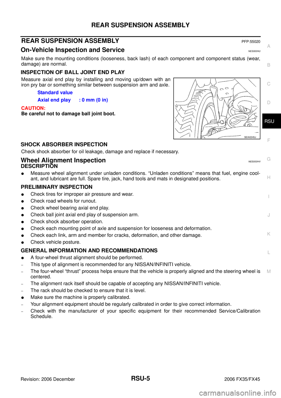
INSPECTION OF BALL JOINT END PLAY
Measure axial end play by installing and moving up/down with an
iron pry bar or something similar between suspension arm and axle.
CAUTION:
Be careful not to damage ball joint boot.
SHOCK ABSORBER INSPECTION
Check shock absorber for oil leakage, damage and replace if necessary.
Wheel Alignment InspectionNES000HV
DESCRIPTION
�Measure wheel alignment under unladen conditions. “Unladen conditions” means that fuel, engine cool-
ant, and lubricant are full. Spare tire, jack, hand tools and mats in designated positions.
PRELIMINARY INSPECTION
�Check tires for improper air pressure and wear.
�Check road wheels for runout.
�Check wheel bearing axial end play.
�Check ball joint axial end play of suspension arm.
�Check shock absorber operation.
�Check each mounting point of axle and suspension for looseness and deformation.
�Check each link, arm and member for cracks, deformation, and other damage.
�Check vehicle posture.
GENERAL INFORMATION AND RECOMMENDATIONS
�A four-wheel thrust alignment should be performed.
–This type of alignment is recommended for any NISSAN/INFINITI vehicle.
–The four-wheel “thrust” process helps ensure that the vehicle is properly aligned and the steering wheel is
centered.
–The alignment rack itself should be capable of accepting any NISSAN/INFINITI vehicle.
–The rack should be checked to ensure that it is level.
�Make sure the machine is properly calibrated.
–Your alignment equipment should be regularly calibrated in order to give correct information.
–Check with the manufacturer of your specific equipment for their recommended Service/Calibration
Schedule. Standard value
Axial end play : 0 mm (0 in)
SEIA0245J
Page 4118 of 4462

SC-12
STARTING SYSTEM
Revision: 2006 December 2006 FX35/FX45
DIAGNOSTIC PROCEDURE 1
Check “B” Terminal Circuit
1. CHECK POWER SUPPLY FOR STARTER MOTOR “B” TERMINAL
1. Remove fuel pump fuse.
2. Crank or start the engine (where possible) until the fuel pressure is released.
3. Turn ignition switch OFF.
4. Make sure that the starter motor “B” terminal E313 terminal 2 connection is clean and tight.
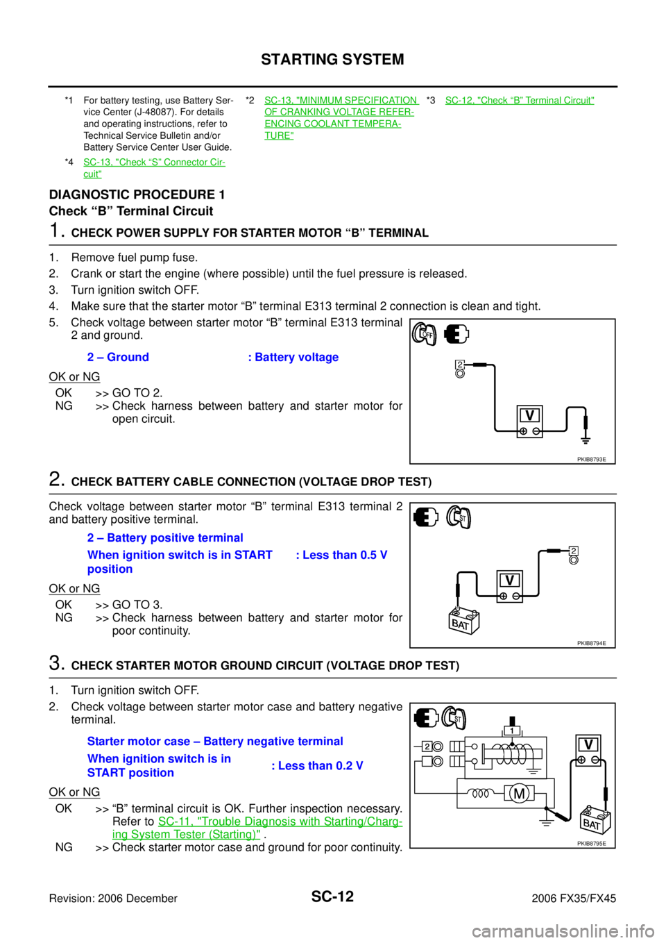
5. Check voltage between starter motor “B” terminal E313 terminal 2 and ground.
OK or NG
OK >> GO TO 2.
NG >> Check harness between battery and starter motor for open circuit.
2. CHECK BATTERY CABLE CONNECTION (VOLTAGE DROP TEST)
Check voltage between starter motor “B” terminal E313 terminal 2
and battery positive terminal.
OK or NG
OK >> GO TO 3.
NG >> Check harness between battery and starter motor for poor continuity.
3. CHECK STARTER MOTOR GROUND CIRCUIT (VOLTAGE DROP TEST)
1. Turn ignition switch OFF.
2. Check voltage between starter motor case and battery negative terminal.
OK or NG
OK >> “B” terminal circuit is OK. Further inspection necessary. Refer to SC-11, "
Trouble Diagnosis with Starting/Charg-
ing System Tester (Starting)" .
NG >> Check starter motor case and ground for poor continuity.
*1 For battery testing, use Battery Ser-
vice Center (J-48087). For details
and operating instructions, refer to
Technical Service Bulletin and/or
Battery Service Center User Guide. *2
SC-13, "MINIMUM SPECIFICATION
OF CRANKING VOLTAGE REFER-
ENCING COOLANT TEMPERA-
TURE"
*3SC-12, "Check “B” Terminal Circuit"
*4SC-13, "Check “S” Connector Cir-
cuit"
2 – Ground : Battery voltage
PKIB8793E
2 – Battery positive terminal
When ignition switch is in START
position : Less than 0.5 V
PKIB8794E
Starter motor case – Battery negative terminal
When ignition switch is in
START position : Less than 0.2 V
PKIB8795E
Page 4119 of 4462

STARTING SYSTEM SC-13
C
D E
F
G H
I
J
L
M A
B
SC
Revision: 2006 December 2006 FX35/FX45
DIAGNOSTIC PROCEDURE 2
Check “S” Connector Circuit
1. CHECK POWER SUPPLY FOR STARTER MOTOR “S” TERMINAL
1. Remove fuel pump fuse.
2. Crank or start the engine (where possible) until the fuel pressure is released.
3. Turn ignition switch OFF.
4. Disconnect starter motor connector.
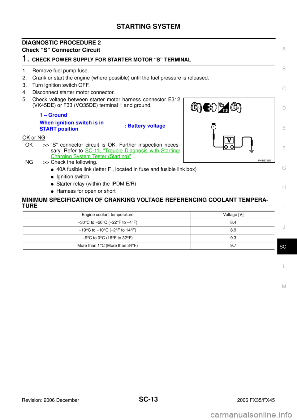
5. Check voltage between starter motor harness connector E312 (VK45DE) or F33 (VQ35DE) terminal 1 and ground.
OK or NG
OK >> “S” connector circuit is OK. Further inspection neces- sary. Refer to SC-11, "
Trouble Diagnosis with Starting/
Charging System Tester (Starting)" .
NG >> Check the following.
�40A fusible link (letter F , located in fuse and fusible link box)
�Ignition switch
�Starter relay (within the IPDM E/R)
�Harness for open or short
MINIMUM SPECIFICATION OF CRANKING VOLTAGE REFERENCING COOLANT TEMPERA-
TURE
1 – Ground
When ignition switch is in
START position : Battery voltage
PKIB8796E
Engine coolant temperature Voltage [V]
− 30 °C to −20 °C ( −22 °F to −4°F) 8.4
− 19 °C to −10 °C ( −2°F to 14 °F) 8.9
− 9°C to 0 °C (16 °F to 32 °F) 9.3
More than 1 °C (More than 34 °F) 9.7