Page 389 of 539
1
CONTROLS AND EQUIPMENT
81
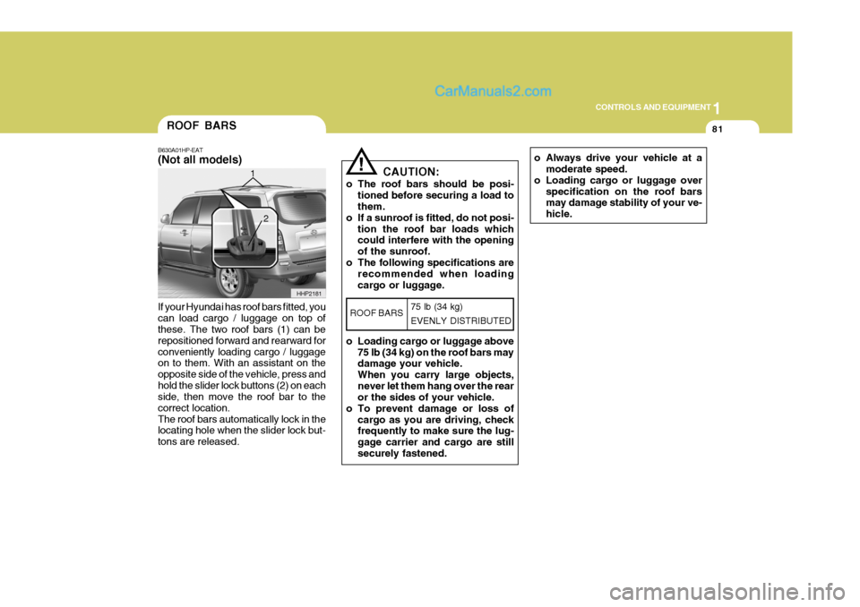
If your Hyundai has roof bars fitted, you can load cargo / luggage on top of these. The two roof bars (1) can be repositioned forward and rearward forconveniently loading cargo / luggage on to them. With an assistant on the opposite side of the vehicle, press andhold the slider lock buttons (2) on each side, then move the roof bar to the correct location.The roof bars automatically lock in the locating hole when the slider lock but- tons are released.ROOF BARS
B630A01HP-EAT (Not all models)
HHP2181
1
2
o Always drive your vehicle at a
moderate speed.
o Loading cargo or luggage over specification on the roof bars may damage stability of your ve- hicle.! CAUTION:
o The roof bars should be posi- tioned before securing a load to them.
o If a sunroof is fitted, do not posi-
tion the roof bar loads whichcould interfere with the opening of the sunroof.
o The following specifications are recommended when loadingcargo or luggage.
o Loading cargo or luggage above 75 lb (34 kg) on the roof bars may damage your vehicle. When you carry large objects,never let them hang over the rear or the sides of your vehicle.
o To prevent damage or loss of cargo as you are driving, checkfrequently to make sure the lug- gage carrier and cargo are stillsecurely fastened.
ROOF BARS 75 lb (34 kg) EVENLY DISTRIBUTED
Page 392 of 539

1CONTROLS AND EQUIPMENT
84SUN VISOR
HHP2017-1
!
When closing the bonnet, slowly close the bonnet and make sure it locks into place.
WARNING:
o Always double check to be sure that the bonnet is firmly latched before driving away. If it is not latched, the bonnet could open whilst the vehicle is being driven,causing a total loss of visibility, which might result in an accident.
o Do not move the vehicle with the bonnet in the raised position, asvision is obstructed and the bon- net could fall or be damaged. B580A01HP-EAT Sun visors are fitted to both the driver and passenger side of the vehicle. Cer-tain derivatives are equipped with a vanity mirror which is located on the back of the passenger visor. The visormay be lowered to reduce the amount of glare from directly ahead, or may be moved towards the side window to re-duce glare from the side of the vehicle, once the inner pivot has been unclipped from the bracket.
B580A01HPVanity mirror
BONNET RELEASE
2. Push the secondary latch lever side-
ways and lift the bonnet.
3. Raise the bonnet by hand.
B570A01HP-EAT
1. Pull the release knob to unlatch the
bonnet. HHP2016-E
HHP2017
Page 394 of 539
1CONTROLS AND EQUIPMENT
86
!
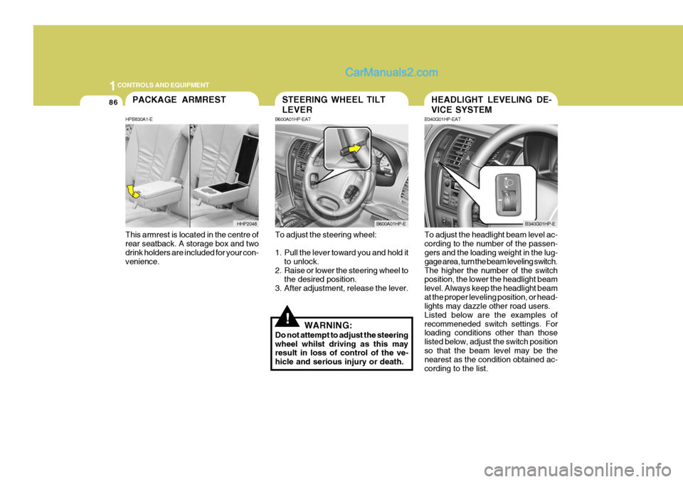
To adjust the steering wheel:
1. Pull the lever toward you and hold it
to unlock.
2. Raise or lower the steering wheel to the desired position.
3. After adjustment, release the lever.
WARNING:
Do not attempt to adjust the steering wheel whilst driving as this may result in loss of control of the ve- hicle and serious injury or death. To adjust the headlight beam level ac-cording to the number of the passen- gers and the loading weight in the lug- gage area, turn the beam leveling switch.The higher the number of the switch position, the lower the headlight beam level. Always keep the headlight beamat the proper leveling position, or head- lights may dazzle other road users. Listed below are the examples ofrecommeneded switch settings. For loading conditions other than those listed below, adjust the switch positionso that the beam level may be the nearest as the condition obtained ac- cording to the list.
STEERING WHEEL TILT LEVER
B600A01HP-EAT
B600A01HP-E
HEADLIGHT LEVELING DE- VICE SYSTEM
B340G01HP-EAT
B340G01HP-E
This armrest is located in the centre of rear seatback. A storage box and two drink holders are included for your con- venience.
PACKAGE ARMREST
HPB830A1-E
HHP2048
Page 404 of 539
1CONTROLS AND EQUIPMENT
96
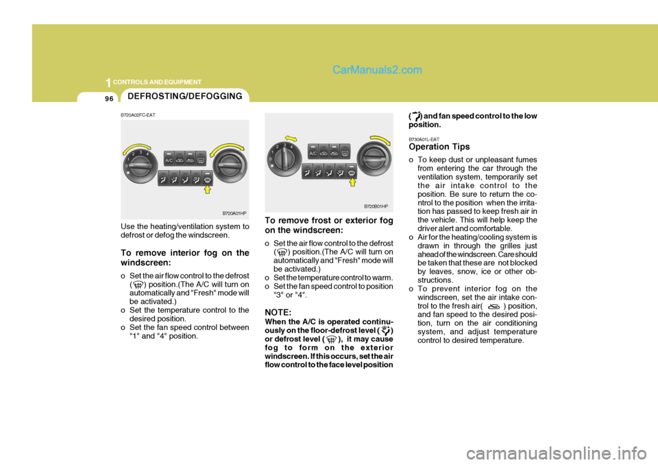
To remove frost or exterior fog on the windscreen:
o Set the air flow control to the defrost( ) position.(The A/C will turn on automatically and "Fresh" mode willbe activated.)
o Set the temperature control to warm.
o Set the fan speed control to position
"3" or "4".
NOTE: When the A/C is operated continu- ously on the floor-defrost level ( ) or defrost level ( ), it may cause fog to form on the exteriorwindscreen. If this occurs, set the air flow control to the face level position ( ) and fan speed control to the low position.
B730A01L-EAT Operation Tips
o To keep dust or unpleasant fumes from entering the car through the ventilation system, temporarily set the air intake control to the position. Be sure to return the co-ntrol to the position when the irrita- tion has passed to keep fresh air in the vehicle. This will help keep thedriver alert and comfortable.
o Air for the heating/cooling system is
drawn in through the grilles justahead of the windscreen. Care should be taken that these are not blocked by leaves, snow, ice or other ob-structions.
o To prevent interior fog on the
windscreen, set the air intake con-trol to the fresh air( ) position, and fan speed to the desired posi- tion, turn on the air conditioningsystem, and adjust temperature control to desired temperature.
Use the heating/ventilation system to defrost or defog the windscreen. To remove interior fog on the windscreen:
o Set the air flow control to the defrost
( ) position.(The A/C will turn on automatically and "Fresh" mode will be activated.)
o Set the temperature control to the desired position.
o Set the fan speed control between "1" and "4" position.DEFROSTING/DEFOGGING
B720A01HP
B720A02FC-EATB720B01HP
Page 415 of 539
1
CONTROLS AND EQUIPMENT
107
!
B750B02Y-EAT Using a cellular phone or a two- way radio When a cellular phone is used inside the vehicle, noise may be producedfrom the audio equipment. This does not mean that something is wrong with the audio equipment. In such a case,use the cellular phone at a place as far as possible from the audio equipment.
CAUTION:
When using a communication sys- tem such a mobile phone or a radio set inside the vehicle, a separate external antenna must be fitted. Whena mobile phone or a radio set is used with an internal antenna alone, it may interfere with the vehicle's elec-trical system and adversely affect safe operation of the vehicle.
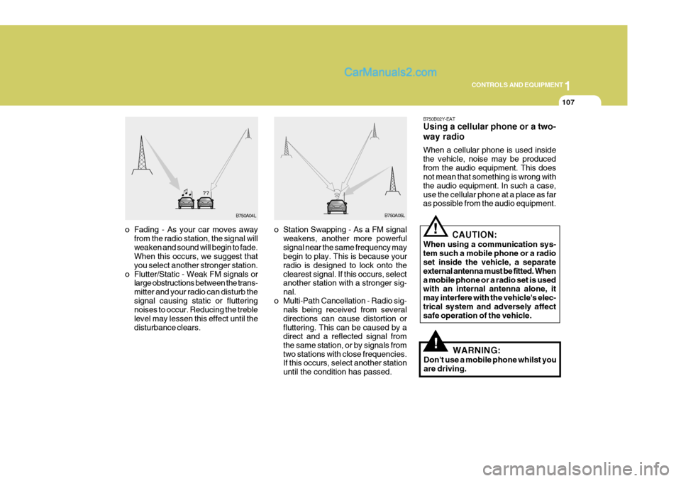
o Fading - As your car moves away
from the radio station, the signal will weaken and sound will begin to fade. When this occurs, we suggest that you select another stronger station.
o Flutter/Static - Weak FM signals or large obstructions between the trans-mitter and your radio can disturb thesignal causing static or fluttering noises to occur. Reducing the treble level may lessen this effect until thedisturbance clears. o Station Swapping - As a FM signal
weakens, another more powerfulsignal near the same frequency may begin to play. This is because your radio is designed to lock onto theclearest signal. If this occurs, select another station with a stronger sig- nal.
o Multi-Path Cancellation - Radio sig- nals being received from severaldirections can cause distortion orfluttering. This can be caused by a direct and a reflected signal from the same station, or by signals fromtwo stations with close frequencies. If this occurs, select another station until the condition has passed.
B750A04L B750A05L
!WARNING:
Don't use a mobile phone whilst you are driving.
Page 416 of 539
1CONTROLS AND EQUIPMENT
108
!
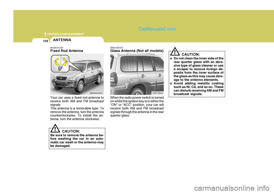
B880C02B-EAT Glass Antenna (Not all models) When the radio power switch is turned on whilst the ignition key is in either the "ON" or "ACC" position, your car will receive both AM and FM broadcastsignals through the antenna in the rear quarter glass. CAUTION:
o Do not clean the inner side of the rear quarter glass with an abra- sive type of glass cleaner or usea scraper to remove foreign de- posits from the inner surface of the glass as this may cause dam-age to the antenna elements.
o Avoid adding metallic coating
such as Ni, Cd, and so on. Thesecan disturb receiving AM and FM broadcast signals.
HHP2184-D
ANTENNA
!
B870A01A-GAT Fixed Rod Antenna Your car uses a fixed rod antenna to receive both AM and FM broadcast signals. This antenna is a removable type. Toremove the antenna, turn the antenna counterclockwise. To install the an- tenna, turn the antenna clockwise.
CAUTION:
Be sure to remove the antenna be- fore washing the car in an auto- matic car wash or the antenna maybe damaged.
B870C01HP-D
Page 417 of 539
2
Engine Exhaust Can Be Dangerous! ............................ 2-2
Before Starting the Engine ............................................ 2-4
Key Positions ................................................................ 2-4Starting ......................................................................... 2-6
Manual Transmission ................................................... 2-8
Automatic Transmission .............................................. 2-10
Four-Wheel Drive (4WD) ............................................. 2-14
Anti-Lock Brake System (ABS) ................................... 2-21
Limited-Slip Differential (LSD) ......................................2-22
Effective Braking ......................................................... 2-22
Driving for Economy .................................................... 2-23
Smooth Cornering ........................................................ 2-24
Winter Motoring ............................................................ 2-24
Trailer and Vehicle Towi ng .......................................... 2-26
DRIVING YOUR HYUNDAI
2
Page 420 of 539
2 DRIVING YOUR HYUNDAI
4
!WARNING:
The engine must never be turned off and the key removed from the igni-tion key cylinder whilst the vehicle is in motion since the steering lock will operate and control of the vehiclewill be lost.
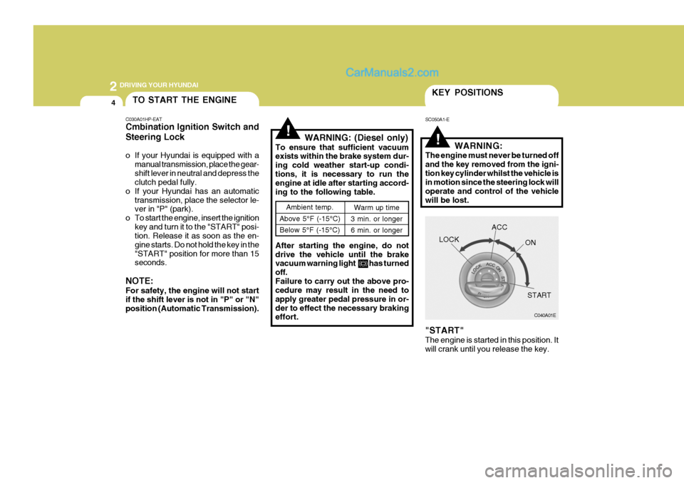
"START" The engine is started in this position. It will crank until you release the key.
Ambient temp.
Above 5°F (-15°C) Below 5°F (-15°C) Warm up time
3 min. or longer 6 min. or longer
!WARNING: (Diesel only)
To ensure that sufficient vacuum exists within the brake system dur- ing cold weather start-up condi-tions, it is necessary to run the engine at idle after starting accord- ing to the following table. After starting the engine, do not drive the vehicle until the brake vacuum warning light has turned off.Failure to carry out the above pro- cedure may result in the need to apply greater pedal pressure in or-der to effect the necessary braking effort.
KEY POSITIONS
SC050A1-E
C040A01E
LOCK
ACC
ON
START
TO START THE ENGINE
C030A01HP-EAT Cmbination Ignition Switch and Steering Lock
o If your Hyundai is equipped with a manual transmission, place the gear- shift lever in neutral and depress the clutch pedal fully.
o If your Hyundai has an automatic transmission, place the selector le-ver in "P" (park).
o To start the engine, insert the ignition
key and turn it to the "START" posi-tion. Release it as soon as the en- gine starts. Do not hold the key in the"START" position for more than 15 seconds.
NOTE: For safety, the engine will not start if the shift lever is not in "P" or "N" position (Automatic Transmission).