Page 49 of 420
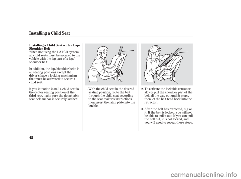
When not using the LATCH system,
all child seats must be secured to the
vehicle with the lap part of a lap/
shoulder belt.With the child seat in the desired
seating position, route the belt
through the child seat according
to the seat maker’s instructions,
then insert the latch plate into the
buckle.To activate the lockable retractor,
slowly pull the shoulder part of the
belt all the way out until it stops,
then let the belt f eed back into the
retractor.
Af ter the belt has retracted, tug on
it. If the belt is locked, you will not
be able to pull it out. If you can pull
thebeltout,itisnotlocked,and
you will need to repeat these steps.
In addition, the lap/shoulder belts in
all seating positions except the
driver’s have a locking mechanism
that must be activated to secure a
child seat.
If you intend to install a child seat in
the center seating position of the
thirdrow,makesurethedetachable
seat belt anchor is securely latched.
1.
2.
3.
Installing a Child Seat
Installing a Child Seat with a L ap/
Shoulder Belt
48
Page 52 of 420
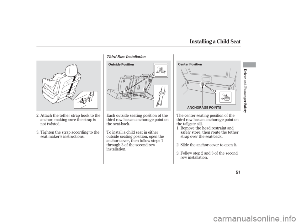
Attach the tether strap hook to the
anchor, making sure the strap is
not twisted.
Tighten the strap according to the
seat maker’s instructions.Remove the head restraint and
safely store, then route the tether
strap over the seat-back.
Slide the anchor cover to open it.
Follow step 2 and 3 of the second
row installation.
The center seating position of the
third row has an anchorage point on
the tailgate sill.
Each outside seating position of the
third row has an anchorage point on
the seat-back.
To install a child seat in either
outside seating position, open the
anchor cover, then f ollow steps 1
through 3 of the second row
installation.
2.
1.
3.
2.
3.
T hird Row Inst allat ion
Installing a Child Seat
Driver and Passenger Saf ety
51
ANCHORAGE POINTS
Center Position
Outside Position
Page 60 of 420

This section gives inf ormation about
the controls and displays that
contribute to the daily operation of
your vehicle. All the essential
controls are within easy reach............................
Control Locations .60............................
Instrument Panel .61
..........
Instrument Panel Indicators .63
.............................................
Gauges .71
.............
Multi-Inf ormation Display .74
Controls Near the Steering
.........................................
Wheel .124
Windshield Wipers and .....................................
Washers .125
Rear Window Wiper and .......................................
Washer .126
.........
Turn Signal and Headlights .126
......
Instrument Panel Brightness .129
...............
Hazard Warning Button .130
...............
Rear Window Def ogger .130
........
Steering Wheel Adjustment .131
.............................
Keys and Locks .132
......................
Immobilizer System .133
..............................
Ignition Switch .134
.....................
Remote Transmitter .135
....................................
Door Locks .141
....................
Power Door Locks .141
............
Childproof Door Locks .142
..........................................
Tailgate .142
..........................
Power Tailgate .143
.................................
Sliding Doors .146
...............................................
Seats .152..................................
Seat Heaters .164
Driver’s Seat Position Memory ........................................
System .165
............................
Power Windows .167
.......................................
Moonroof .170
...........................................
Mirrors .171
...............................
Parking Brake .172
.
Adjustable Driver’s Foot Pedals .173
.........
Interior Convenience Items .174
..........
Retractable Center Tray .175
.....................
Beverage Holders .175
................
Integrated Sunshade .177
....................
Sunglasses Holder .178
................
Conversation Mirror .178
...................................
Sun Visor .179
............................
Vanity Mirror .179
...................
Rear Compartment .179
Removable Second Row
..................................
Console .180
...............
In-Floor Storage Area .181
......................
Lower Glove Box .184
......................
Upper Glove Box .184
...........................
Center Pocket .185
........
Accessory Power Sockets . 186
.......................
AC Power Outlet .186
...............................
Interior Lights .187
Instruments and Controls
Inst rument s and Cont rols
59
Page 61 of 420
Control L ocations
60
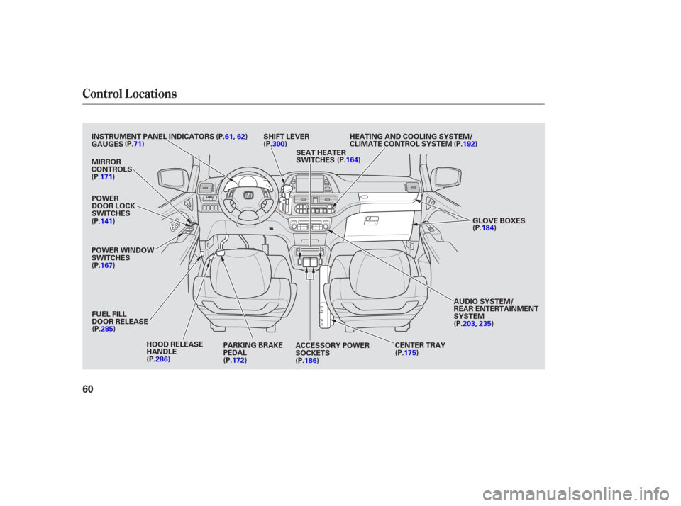
AUDIO SYSTEM/
REAR ENTERTAINMENT
SYSTEM
PARKING BRAKE
PEDAL
FUEL FILL
DOOR RELEASE
HOOD RELEASE
HANDLE
POWER WINDOW
SWITCHES
POWER
DOOR LOCK
SWITCHES
INSTRUMENT PANEL INDICATORS
SHIFT LEVER
MIRROR
CONTROLS
ACCESSORY POWER
SOCKETS
(P.61,62)
GAUGES (P.71) HEATING AND COOLING SYSTEM/
CLIMATE CONTROL SYSTEM
CENTER TRAY
SEAT HEATER
SWITCHES
GLOVE BOXES
(P.141)
(P.167)
(P.285) (P.286) (P.172)(P.186) (P.175)(P.203,235)(P.184)
(P.192)
(P.164)
(P.300)
(P.171)
Page 127 of 420
�µ
Rotate the switch clockwise to
turn the rear window wiper ON.
Hold past ON to turn the window
wiper on and the window washer
on.
OFF
Rotate the switch
counterclockwise to spray the
window washer without activating
the wiper.Turn signal
Of f
Parking and indicator lights
AUTO (Touring models only)
Headlights on
High beamsFlashhighbeams
Fog lights of f (Touring models
only)
Fog lights on (Touring models
only)
When you shif t the transmission to
the reverse position with the f ront
windshield wiper activated, the rear
wiper operates automatically even if
the rear wiper switch is of f .
Push down on the
lever to signal a lef t turn and up to
signal a right turn. To signal a lane
change, push lightly on the lever,
and hold it. The lever will return to
center when you release it or
complete a turn.
1.
2.
3.
4. 7.
8.
9.
1.
2.
3.
4.
5.
6.
Rear Window Wiper and Washer
Turn Signal and Headlights Turn Signal
Windshield Wipers and Washers, Turn Signal, Headlights
126
Page 131 of 420
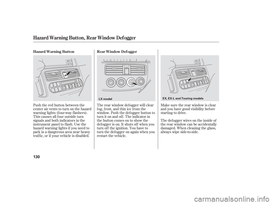
Push the red button between the
center air vents to turn on the hazard
warning lights (f our-way f lashers).
This causes all f our outside turn
signals and both indicators in the
instrument panel to f lash. Use the
hazard warning lights if you need to
park in a dangerous area near heavy
traf f ic, or if your vehicle is disabled.The def ogger wires on the inside of
the rear window can be accidentally
damaged. When cleaning the glass,
always wipe side-to-side. Make sure the rear window is clear
and you have good visibility bef ore
starting to drive.
The rear window def ogger will clear
fog, frost, and thin ice from the
window. Push the def ogger button to
turn it on and off. The indicator in
the button comes on to show the
def ogger is on. It shuts of f when you
turn of f the ignition. You have to
turn the def ogger on again when you
restart the vehicle.
Hazard Warning Button
Rear Window Def ogger
Hazard Warning Button, Rear Window Def ogger
130
LX model EX, EX-L and Touring models
Page 153 of 420
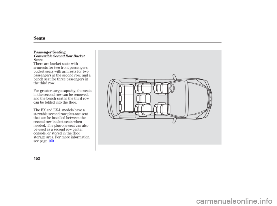
There are bucket seats with
armrests for two front passengers,
bucket seats with armrests for two
passengers in the second row, and a
bench seat f or three passengers in
the third row.
For greater cargo capacity, the seats
in the second row can be removed,
andthebenchseatinthethirdrow
can be f olded into the f loor.
The EX and EX-L models have a
stowable second row plus-one seat
that can be installed between the
second row bucket seats when
needed. The plus-one seat can also
be used as a second row center
console, or stored in the f loor
storage area. For more inf ormation,
see page .160
Passenger Seating
Convert ible Second Row Bucket
Seat s
Seats
152
Page 157 of 420
See page f or important saf etyinf ormation and a warning about how toproperly position the head restraints. 15
On EX, EX-L and Touring models On EX-L and Touring models
Your vehicle is equipped with head
restraints in all seating positions to
help protect you and your
passengers f rom whiplash and other
injuries.
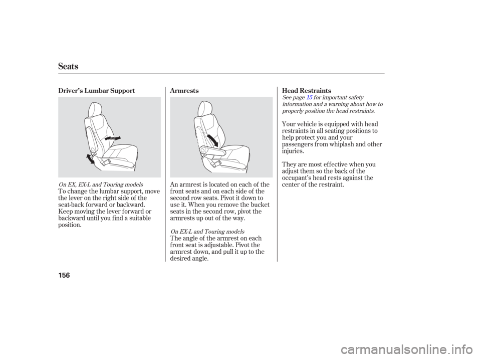
An armrest is located on each of the
frontseatsandoneachsideof the
second row seats. Pivot it down to
use it. When you remove the bucket
seats in the second row, pivot the
armrests up out of the way.
To change the lumbar support, move
the lever on the right side of the
seat-back forward or backward.
Keep moving the lever f orward or
backward until you f ind a suitable
position. They are most ef f ective when you
adjust them so the back of the
occupant’s head rests against the
center of the restraint.
Theangleof thearmrestoneach
f ront seat is adjustable. Pivot the
armrest down, and pull it up to the
desired angle. Head Restraints
Armrests
Driver’s L umbar Support
Seats
156