2006 GREAT WALL HOVER change time
[x] Cancel search: change timePage 17 of 425

Brake system
The front wheel brake is ventilation coil type, the rear wheel brake is disk and drum type. The service brake type is that the double-
loop vacuum assist hydraulic brake is applied on the front and rear disc brake. The parking brake is mechanical dragline acting on the
drum brake of the rear wheel.
The free stroke of brake pedal is 20mm
30mm, and the operating stroke of the pedal is 120mm. The operating stroke of the brake
handle is 17
(3 teeth)30(8 teeth).
1. The adjustment of brake pedal
Measure the operating stroke of the brake pedal, the standard value is 120mm. When the eighth is no in compliance with the
requirement, make adjustment according to the following procedures:
a. Separate the brake lamp switch wire connector, loosen the blocking nut, and turn the brake lamp switch to the position that the
stopper is not touched;
b. Unscrew the blocking nut of the operation connecting rod, use the thinnose pliers to turn the operation connecting rod, adjust
the brake pedal height to standard value, after reaching the standard value, tighten the lock nut;
c. Turn the brake lamp switch to the position that the stopper of brake pedal is just touched, continue the turning for 1/2
1 circle,
and tighten the blocking nut;
d. Connect the brake lamp switch wire connector;
e. The brake lamp should not be light when the brake pedal is in release status.
2. Standard value of brake pedal free stroke: 20-30 mm
a. Under the stopping status of the engine, step on the brake pedal for 2
3 times, clear the influence of brake assistor, then use
hand to push the brake pedal to the position that there is resistance, measure the amount of movement (free stroke). It shall
be in compliance with the regulation of standard value;
b. If the gap is less than the regulation value, check to see whether the gap between the carrier rod of brake lamp switch and the
brake pedal is in compliance with the regulation. If this gap is exceeding the regulation, it means that the gap between the drive
rod clevis pin and the brake pedal arm is exceeding the regulated value.
3. Start the engine, step down the brake pedal with a force of about 700N,ehck the main brake pump, whether there is oil
leakage on the connection positions of the brake pipeline. If there is, maintain it.
4. Operating status test of brake assistor
Conduct the operation status test of the brake assistor according to the following methods:
a. Start the engine, stop if after operating for 1
2 minutes. Step on the brake pedal for several times with normal force. Expect
that the pedal can be fully stepped down a the first stepping, the height of the brake pedal shall be raised on and on with the
stepping, thus means that the brake assistor operates normally, if the height of the pedal is not changed, it means that the brake
assistor is damaged;
b. Under the stopping status of the engine, step on the brake pedal for several times, confirms that the height of brake pedal is
elevated on and on, under the status that the brake pedal is stepped down, start the engine. At this time, the brake pedal will
move down a bit, it means that the brake assistor is working normally. If the brake pedal is moving upwards, it means that the
brake assistor is damaged;
c. Under the operation status of the engine, step down the brake pedal to stop the operation of the engine. AT this time, the there
shall be no change of the height of brake pedal within 30 seconds, it means that the brake assistor is working normally. If the
brake pedal is moving upwards, it means that the brake pedal assistor is damaged.
5. Adjustment of the parking brake system:
a.For positioning, pull the brake bar to the limit position for over 3 times, use a force of about 400N to pull the brake parking
lever, count the number of knocking teeth. The standard value of stroke of parking brake : 17
(3 teeth) 30(8 teeth);
b.If the stroke of brake parking lever is too big and not in compliance with the requirement, adjust it with the following methods:
Loosen the brake parking lever, unscrew the adjusting nut.
Remove the adjuster hole cap from the brake assembly, use screwdriver to turn the adjustor in the arrow direction to the limit
that the brake drum cannot turn.
Rotate 5 teeth in the counter arrow direction.
Rotate the adjusting nut, adjust the brake parking lever stroke to the standard value.
c. If the stroke is less than the standard value, unscrew the adjusting nut to make it reach the standard value.
d. Check to see whether the adjusting nut and the rod are loosened, whether the adjusting nut is fixed in the fixed seat.
e. After adjustment, jack up the rear part of the car. Loosen the brake parking lever, the brake disc shall not be dragged when
checking the rear wheel.
f. The breaking in of the parking brake: use the force of about 200-250N to pull the brake parking lever,drive the car for about
400m with a speed of about 60km/h, repeat for 2-3 times, then test on the slope of 30%, the car shall be able to be parked.
Page 93 of 425

Automatic transmission-17
Figure 3.10 1-2 gear shift valve
Clutch combination regulating valve (refer to Figure 3.15) is a constant ratio regulating valve which provide the regulating pressure
of clutch C1 to control the change ratio of shifting quality clutch status. The ratio is about 2.25:1.
When the S3 is opened, the oil of 3
rd-Gear is provided to the valve and adjust the pressure (CAF) to 2.25 times of S5 signal
pressure. When S3 is in closed status, the output pressure is 2.25 times of pressure of line 500.
9. Clutch combination regulating valve
Page 130 of 425

3. Oil filling of service after sales
Set the liquid level position correctly; the procedure is shown as follows:
a. Shut down the engine; place the gear-position in the P-Gear.
b . Lift the vehicle (or place it above the trench).
c. Clean the around of plug before remove it. Remove the oil plug and check the O-ring for damage, finally connect the oil filling
pump to the oil filling hole.
d. Lower the vehicle and oil filling pump to the ground; fill with the transmission fluid partially. The general oil filling amount
is shown as follows:
If in the status of transmission hydraulic torque converter is empty: 8.0 L
If in the status of transmission hydraulic torque converter is full: 3.8 L
e. When start the vehicle in P-Gear, rotate the engine in idle speed. Step down the foot brake, pull the shifting lever in each gear-
position in circulation and add the transmission fluid until the action of each gear-position can be sensed.
f. Then fill with 0.5L transmission fluid (ATF) additionally.
g. Shut off the engine, lift the vehicle; take off the pump and replace the plug. Ensure the plug is tightened according to the
specification.
h. Then pull the vehicle throttle position for slight opening to make the vehicle runs for 3.5
4.5km; the rotary speed of engine
is no more than 2500r/min; then the transmission fluid temperature will in the scope of 50
60.
i. The engine is in idle-speed; pull the hand brake to make the shifting lever circuits in each gear-position horizontal status.
k. Remove the filling plug 3 minutes after the engine is shut off, but must be no more than1 hour. At this time, the correct
level position should be in the bottom of oil filling hole. If does not reach the liquid level position, then fill with few
transmission fluid (ATF) to meet the requirement.
l. Reinsert the transmission fluid plug, remove the residual transmission fluid around the vehicle and transmission; tighten the
plug to the specified torque.
4. Replace the ATF
Please notice that the color of TQ95 automatic transmission oil will be faded in the normal operation of transmission; it will be
turn into the deep brown or even in black. It will not affect the performance of ATF. It means that the fading of transmission
fluid not always means to replace the transmission fluid.
If the transmission temperature is raised, the ATF will be burnt. In this condition, ATF will change into black and with special
sulfur smell. The smell of the ATF means the oil is burnt.
If the ATF is burnt, it will cause the damage of transmission (the clutch assembly is damaged at least).At this time, it should
disassembly the transmission and process the necessary detection.
Electronic calibration
1. Idle-speed calibration
The idle-speed calibration is introduced in detail in the vehicle factory manual.
2 Calibration of position of throttle position
If the throttle position information stored in TCU is lost or not in application scope. It can be reestablished according to the
following program as the diagnosis error information.
a. Check whether the engine idle speed is in required range.
b. In the status of shutting off of air-condition, make the engine is in “D” –Gear for 60s,then the reference point with opening
degree of 0
of throttle position is reset in TCU.
Shut off the engine; switch on the ignition device, step the accelerator pedal to bottom for 60s, then the reference point with opening
degree of 100
of throttle position is reset in TCU.
3. Clear of throttle position
The clear process set by learning throttle position is necessary for M88 transmission TCU.
4. Car code
For M88 transmission, the car code is unnecessary.
Page 292 of 425

Brake-6
4. Adjust the stroke of pedal if necessary
a. Rotate the pedal push bar to adjust the free stroke if the stroke
length is improper.
b. Start the engine to confirm the free stroke of pedal.
c. Check the height of pedal after adjusts the free stroke of pedal.
d. The height difference of brake pedal and clutch pedal to front
apron is 0
8mm.
e. The height difference of brake pedal and accelerator pedal to the
front apron is 45
5mm.
Vacuum assist
Remarks:
Use the vacuum assist tester to check the operation of vacuum
assist if possible.
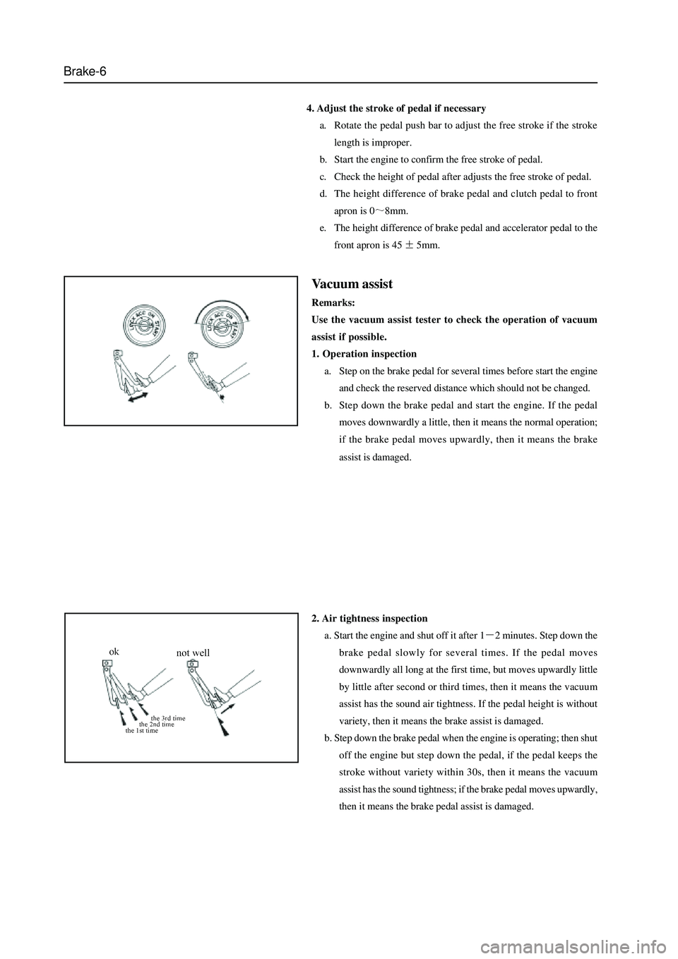
1. Operation inspection
a. Step on the brake pedal for several times before start the engine
and check the reserved distance which should not be changed.
b. Step down the brake pedal and start the engine. If the pedal
moves downwardly a little, then it means the normal operation;
if the brake pedal moves upwardly, then it means the brake
assist is damaged.
2. Air tightness inspection
a. Start the engine and shut off it after 1
2 minutes. Step down the
brake pedal slowly for several times. If the pedal moves
downwardly all long at the first time, but moves upwardly little
by little after second or third times, then it means the vacuum
assist has the sound air tightness. If the pedal height is without
variety, then it means the brake assist is damaged.
b. Step down the brake pedal when the engine is operating; then shut
off the engine but step down the pedal, if the pedal keeps the
stroke without variety within 30s, then it means the vacuum
assist has the sound tightness; if the brake pedal moves upwardly,
then it means the brake pedal assist is damaged.
Page 367 of 425

CD Player and Air Conditioning System-14
Pumping Out of A i r Conditioning System to the Vacuum and Addition of Refrigeration Oil
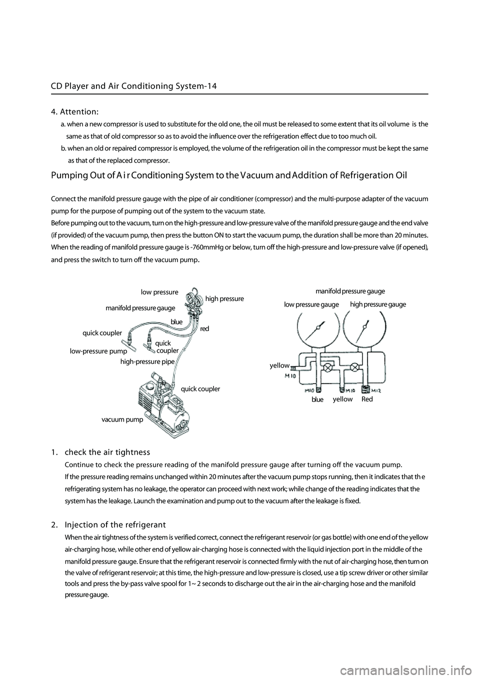
Connect the manifold pressure gauge with the pipe of air conditioner (compressor) and the multi-purpose adapter of the vacuum
pump for the purpose of pumping out of the system to the vacuum state.
Before pumping out to the vacuum, turn on the high-pressure and low-pressure valve of the
manifold pressure gauge and the end valve
(if provided) of the vacuum pump, then press the button ON to start the vacuum pump, the duration shall be more than 20 minutes
.
When the reading of manifold pressure gauge is -760mmHg or below, turn off the high-pressure and low-pressure valve (if opened)
,
and press the switch to turn off the vacuum pum
p.
1 . check the air tightness
Continue to check the pressure reading of the manifold pressure gauge after turning off the vacuum pump.
If the pressure reading remains unchanged within 20 minutes after the vacuum pump stops running, then it indicates that th
e
refrigerating system has no leakage, the operator can proceed with next work; while change of the reading indicates that the
system has the leakage. Launch the examination and pump out to the vacuum after the leakage is fixed.
2 . Injection of the refrigerant
When the air tightness of the system is verified correct, connect the refrigerant reservoir (or gas bottle) with one end of the yellow
a ir-charging hose, while other end of yellow air-charging hose is connected with the liquid injection port in the middle of the
manifold pressure gauge. Ensure that the refrigerant reservoir is connected firmly with the nut of air-charging hose, then turn on
the valve of refrigerant reservoir; at this time, the high-pressure and low-pressure is closed, use a tip screw driver or other
similar
tools and press the by-pass valve spool for 1~ 2 seconds to discharge out the air in the air-charging hose and the manifold
pressure gauge.
low p ressure
high pressure
manifold pressure gauge
quick coupler
l ow-pressure pump
high-pressure pipe
quick coupler
quick
coupler
red
blue
vacuum pum
p
manifold pressure gauge
low pressure gauge high
pressure gauge
Red
blue
yellow
yellow
4. Attention:
a. when a new compressor is used to substitute for the old one, the oil must be released to some extent that its oil volume is the
same as that of old compressor so as to avoid the influence over the refrigeration effect due to too much oil.
b. when an old or repaired compressor is employed, the volume of the refrigeration oil in the compressor must be kept the sam
e
as that of the replaced
compressor.