2006 FORD TRANSIT vehicle speed
[x] Cancel search: vehicle speedPage 4 of 234

3.7Exhaust System..........................86
3.7.1Extensions and Optional Exhausts....
86
3.7.2Exhaust Pipes and Supports.............86
3.7.3Exhaust Heat Shields..........................86
3.8Fuel System.................................88
4 Electrical
4.1Communications Network..........90
4.1.1CAN-Bus System Description and
Interface................................................90
4.1.2Central Junction Box (CJB)................91
4.1.3Circuit Diagram....................................93
4.2Module Communications
Network—Specifications.............94
4.2.1Circit Diagram......................................94
4.3Charging System.........................95
4.3.1General Information and Specific
Warnings...............................................95
4.3.2Power Management Settings...........95
4.3.3Electrical Conversions........................95
4.3.4Fitting of Equipment Containing an
Electric Motor.......................................97
4.3.5Vehicle Electrical Capacity -
Alternator..............................................97
4.3.6Charge Balance Guidelines...............97
4.3.7Circuit Diagrams..................................97
4.4Battery and Cables.....................98
4.4.1Battery Information.............................98
4.4.2Generator and Alternator.................103
4.5Climate Control System.............106
4.6Instrument Cluster.....................107
4.7Horn...........................................108
4.8Tachograph................................109
4.8.1Legislation...........................................109
4.8.2Tachograph Mounting.......................110
4.9Information and Entertainment
System - General
Information—Specifications.......112
4.9.1Radio Connector................................112
4.9.2Possible Accessories.........................113
4.10Cellular Phone............................115
4.11Exterior Lighting.........................116
4.11.1Reversing Lamps...............................116
4.11.2Additional External Lamps................116
4.11.3Lamps – Hazard / Direction
Indication..............................................117
4.11.4Lamps – Front and Rear Fog Lights....
117
4.11.5Lamps for Wide Vehicles...................117
4.11.6Electrically operated Door Mirrors....
117
4.12Interior Lighting..........................118
4.12.1Additional Internal Lamps .................118
4.12.2Additional 'Theatre Lighting' for rear
of vehicle interior................................118
4.13Fuses and Relays.......................119
4.13.1Wiring Specification............................119
4.13.2Auxiliary Fuses, Fuse Box and Relays
(Fuses - Standard).............................119
4.13.3Customer Connection Points..........120
4.13.4Special Vehicle Option Auxiliary Fuse
Box........................................................121
4.13.5Additional Ignition, Instrument Panel
Illumination and Air Conditioning On
Signals.................................................124
4.13.6Relays and Switches.........................127
4.13.7Windscreen wipers...........................130
4.14Special Conversions..................131
4.14.1Vehicle Speed Output (Signal).........131
4.14.2Engine Run Signal (D+ Alternative)....
132
4.14.3Connectors.........................................133
4.14.4Installation and Routing Guides.......134
4.14.5Electrics for Tow bar.........................136
4.14.6Ground Points....................................140
4.14.7Special Vehicle Options (SVO) and
Aftermarket Kits.................................146
4.14.8Additional Vehicle Signals / Features..
147
4.14.9Engine RPM (Revs Per Minute) Speed
Controller.............................................157
4.14.10Adding Connectors, Terminals and
Wiring...................................................162
5 Body and Paint
5.1Body...........................................175
5.1.1Body Structures - General
Information..........................................175
5.1.2Back Panel Removal.........................177
5.1.3Integrated Bodies and Conversions...
177
5.1.4Chassis Cab........................................179
5.1.5Cab Van Floor.....................................185
5.1.6Hydraulic Lifting Equipment for Van,
Bus, Kombi and Chassis Cab..........186
5.1.7Partitions (Bulkhead) - Driver and
Front Passenger(s) Protection on Van,
Bus and Kombi..................................192
5.1.8Racking Systems...............................194
5.1.9Front End Integrity for Cooling, Crash,
Aerodynamics and Lighting.............198
5.1.10Tipper Bodies.....................................199
5.1.11Tank and Dry Bulk Carriers...............199
5.2Body System - General
Information—Specifications......200
5.2.1Van Floor - Load Compartment Tie
Downs for Van ,Bus and Kombi.....200
5.3Body Closures..........................203
5.3.1Load Compartment Interior Lining....
203
5.3.2Security, Anti Theft and Locking
System Security ...............................203
5.4Rear View Mirrors.....................208
5.4.1Mirrors for Wide Vehicles.................208
5.5Seats.........................................209
5.5.1Rear Seat Fixings Positions - Kombi...
209
5.5.2Heated Seats.....................................210
5.6Glass, Frames and Mechanisms...
211
5.6.1Rear Windows....................................211
Table of Contents
4
Page 24 of 234

1.6 Electromagnetic Compatibility (EMC)
The base vehicle has been tested and certified
to all relevant legislation relating to
Electromagnetic Compatibility. All retrofitted
equipment must also comply with the relevant
legislation.
In addition, 2-way radio communication and other
equipment with built in radio transmitters (for
example anti-theft alarms, tracking devices)
should only be fitted to the vehicle if they operate
within the listed frequency bands and do not
exceed the maximum transmission output power
specified below
Frequency Overview
Maximum Output
Power (W)
Frequency (MHz)
501-54
5068-87.5
50142-176
50220-225
50380-512
10806-940
101200-1400
101710-1885
101885-2025
1.6.1 Antenna Location
The antenna can be placed on the roof of the
vehicle with the exception of cellular phone car
kits which transmit power below 2W. Such low
power devices may also be installed at the
bottom of the A-pillar behind the trim or on the
front windscreen.
Installation must be performed by suitably
qualified personnel in accordance with the
equipment manufacturer's installation instructions
and comply with the ISO technical specification
ISO/TS 21609: Road Vehicles - Electromagnetic
Compatibility guidelines for the installation of after
market radio frequency transmitting equipment.
In addition, the following guidelines must be
followed during installation:
•Do not mount any transceiver, microphones,
speakers or any other item in the deployment
path of the airbag system.
•Do not attach antenna cables to any part of
the original vehicle wiring or fuel and brake
pipes.
•Antenna and power cables must be a
minimum of 100mm from any electronic
modules and airbags.
•Make sure that any additional power feed is
taken directly from the SVO fuse box (when
available) or a recommended connection
point.
•Power and ground cables should be of higher
current capacity that the protection fuse.
Ground feed must be taken directly to the
battery.
Post installation checks must be made for
disturbances from and to all electrical equipment
in the vehicle both in the standby and transmit
modes. Checks should be carried out with the
ignition ON, engine running and be followed by a
road test at various speeds.
FordTransit 2006.5 (April 2006–)
Date of Publication: 12/2006
1 General Information
24
Page 77 of 234

3.3 Accessory Drive
When the correct belt is used, tensioning is and
remains fully automatic for the life of the belt.
CAUTIONS:
Only use the manufacturers
recommended (or equivalent
specification) components
Make sure that the ancillary pulley
diameter is less than the crankshaft
pulley diameter.
Systems requiring a unique belt
NOTE: For further information please contact
your local National Sales Company
representative, or Local Ford Dealer. If they are
unable to help you then please contact the
Vehicle Converter Advisory Service at
[email protected].
The eigenfrequency of any bracket including the
auxiliary added should be above the maximum
excitation frequency of the main excitation order
of the individual engine at engine top speed. On
4-cylinder inline engines, this is the second
engine order.
3.3.1 Front End Accessory Drive
2.4l Diesel and 2.3l Petrol
CAUTION: Do not fit an additional
front end accessory drive to a
vehicle already equipped with and
air-conditioning compressor.
When engineering and installing a new front end
accessory drive, i.e. belt drive of the crankshaft
pulley, the longitudinal alignment must be within
+/- 0.25mm and angular within +/- 0.33°.
For most front end accessory drive applications
the longer Regular Production Option air
-conditioning belt can replace the standard belt
and pulley layout.
The maximum power that is available for front
end accessory drive applications, in lieu of the
air conditioning compressor is 26Nm torque at
any engine speed up to a maximum of 6kW.
FordTransit 2006.5 (April 2006–)
Date of Publication: 12/2006
3 Powertrain
77
Page 79 of 234

Front End accessory Drive Assembly on 2.3l Petrol Engine
Pulley and Belt Layout on 2.3l Petrol Engine
DescriptionItem
Alternator1
Idler2
Coolant Pump3
Power Steering Pump4
Compressor (may be replaced by ancillary unit)5
Crankshaft Pulley6
Auto Tensioner7
3.3.2 Front End Accessory Drive
2.2l Diesel
CAUTION: Do not fit an additional
front end accessory drive to a
vehicle already equipped with and
air-conditioning compressor.
When engineering and installing a new front end
accessory drive, i.e. belt drive of the crankshaft
pulley, the longitudinal alignment must be within
+/- 0.25mm and angular within +/- 0.33°.
The maximum power that is available for front
end accessory drive applications, in lieu of the
air conditioning compressor is 26Nm torque at
any engine speed up to a maximum of 6kW.
FordTransit 2006.5 (April 2006–)
Date of Publication: 12/2006
3 Powertrain
79E742191234567
Page 83 of 234

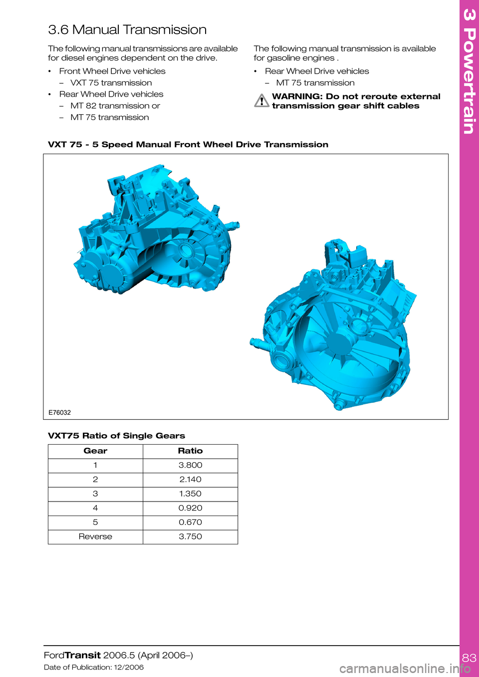
3.6 Manual Transmission
The following manual transmissions are available
for diesel engines dependent on the drive.
•Front Wheel Drive vehicles
–VXT 75 transmission
•Rear Wheel Drive vehicles
–MT 82 transmission or
–MT 75 transmission
The following manual transmission is available
for gasoline engines .
•Rear Wheel Drive vehicles
–MT 75 transmission
WARNING: Do not reroute external
transmission gear shift cables
VXT 75 - 5 Speed Manual Front Wheel Drive Transmission
VXT75 Ratio of Single Gears
RatioGear
3.8001
2.1402
1.3503
0.9204
0.6705
3.750Reverse
FordTransit 2006.5 (April 2006–)
Date of Publication: 12/2006
3 Powertrain
83E76032
Page 90 of 234

4.1 Communications Network
4.1.1 CAN-Bus System Description
and Interface
WARNING: Do not tamper with, cut
into or connect to any of the
CAN-Bus interface wiring or
connectors. The addition of
unapproved CAN-Based modules
could impact the safe operation of
the vehicle.
CAN uses propriety message sets to
communicate between the devices shown, via
Medium Speed (MS), High Speed (HS), Private
and Public Buses. In addition there is localised
application of LIN and ISO 9141 K-line serial links.
CAN-Bus System
DescriptionItem
High Speed CAN1
Medium Speed CAN2
Medium Speed CAN(Multimedia)3
ISO9141 K-line4
LIN BUS5
Private High Speed CAN6
FordTransit 2006.5 (April 2006–)
Date of Publication: 12/2006
4 Electrical
90BQP1RSLKMNEFGHJA23456E74853
Page 110 of 234

Digital (DTCO) Tachograph
Pin Assignment
For detailed information about pin assignments
please contact your local National Sales Company
representative or Siemens VDO directly.
Wiring
NOTE: Not all instrument panel looms contain
tachograph wiring.
The tachograph wiring consists of two parts:
•Speed sensor harness – this is a separate part
which attaches to the instrument panel
harness at the junction of the firewall and floor
pan, close to the centre of the vehicle.
•Instrument panel harness – this contains the
remainder of circuits for the tachograph.
4.8.2 Tachograph Mounting
Standard Ford installation uses a pod on top of
the instrument panel. The tachograph mounts in
the aperture nearest the instrument cluster. Note
the rear mounting bracket in the centre of the
DIN aperture in the below diagram E75503.
FordTransit 2006.5 (April 2006–)
Date of Publication: 12/2006
4 Electrical
110E75502
Page 111 of 234

Tachograph Mounting - Double DIN
DescriptionItem
Rear Mounting Bracket for Tachograph1
Tachograph Speed Sensor Mounting
The tachograph requires a dedicated speed
sensor mounted to the transmission. The position
varies depending on the transmission type.
Vehicles specified without tachograph may not
have the appropriate sensor mounting position
FordTransit 2006.5 (April 2006–)
Date of Publication: 12/2006
4 Electrical
111E755031