2006 FORD TRANSIT oil
[x] Cancel search: oilPage 61 of 234

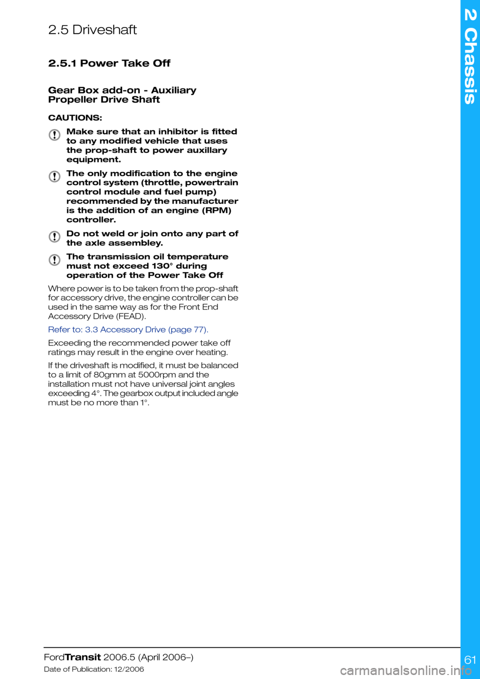
2.5 Driveshaft
2.5.1 Power Take Off
Gear Box add-on - Auxiliary
Propeller Drive Shaft
CAUTIONS:
Make sure that an inhibitor is fitted
to any modified vehicle that uses
the prop-shaft to power auxillary
equipment.
The only modification to the engine
control system (throttle, powertrain
control module and fuel pump)
recommended by the manufacturer
is the addition of an engine (RPM)
controller.
Do not weld or join onto any part of
the axle assembley.
The transmission oil temperature
must not exceed 130° during
operation of the Power Take Off
Where power is to be taken from the prop-shaft
for accessory drive, the engine controller can be
used in the same way as for the Front End
Accessory Drive (FEAD).
Refer to: 3.3 Accessory Drive (page 77).
Exceeding the recommended power take off
ratings may result in the engine over heating.
If the driveshaft is modified, it must be balanced
to a limit of 80gmm at 5000rpm and the
installation must not have universal joint angles
exceeding 4°. The gearbox output included angle
must be no more than 1°.
FordTransit 2006.5 (April 2006–)
Date of Publication: 12/2006
2 Chassis
61
Page 62 of 234

2.6 Brake System
2.6.1 General
The Brake System must be fully functional when
the vehicle conversion is completed. The vehicle
brake operating modes must be checked,
including warning system and parking brakes.
Brakes are certified to 71/320EEC and ECE R13
requirements as amended.
WARNING: Do not restrict the airflow
and cooling to the brake system
CAUTION: Spoilers and wheel covers
must not affect the brake cooling
performance.
NOTE: Do not obstruct the view of the brake
fluid reservoir level
NOTE: The donor vehicle brake fluid reservoir is
translucent so that it is possible to check the level
of fluid without opening the reservoir which will
reduce the risk of contamination.
The brake fluid reservoir must remain accessible
for servicing and for adding brake fluid.
2.6.2 Kerb Mass Data
NOTE: For further information please contact
your local National Sales Company representative,
or Local Ford Dealer. If they are unable to help
you then please contact the Vehicle Converter
Advisory Service at [email protected].
2.6.3 Brake Hoses General
CAUTION: Make sure that the front
and rear brake hoses are not
twisted and are correctly located
away from body and chassis
components.
Front and rear brake hoses must not rub, chafe
or rest on body or chassis components. There
must be clearance under all operating conditions,
between full compression and extension and full
lock to lock.
Brake lines must not be used to support or
secure any other component.
FordTransit 2006.5 (April 2006–)
Date of Publication: 12/2006
2 Chassis
62
Page 128 of 234

Micro Relay Parameters
20 ampsNormally open contacts
16 ampsNormally closed contacts
300 mA (max)Nominal coil current
Medium current changeover relay - Part number:6G9T-14B192-B_
Medium current normally open relay - Part number: 6G9T-14B192-A_ (pin 4 not present)
Mini relay
Mini Relay Parameters
40 ampsNormally open contacts
20 ampsNormally closed contacts
300 mA (max)Nominal coil current
Medium current changeover relay - Part number: 6G9T-14B192-D_
Medium current normally open relay - Part number: 6G9T-14B192-C_ (pin 4 not present)
Mini Power Relay
Mini Power Relay Parameters
70 ampsNormally open contacts
300 mA (MAX)Nominal coil current
High current normally open relay - Part number: 6G9T-14B192-E_
FordTransit 2006.5 (April 2006–)
Date of Publication: 12/2006
4 Electrical
128E750181234512354 E7501912351235
Page 129 of 234

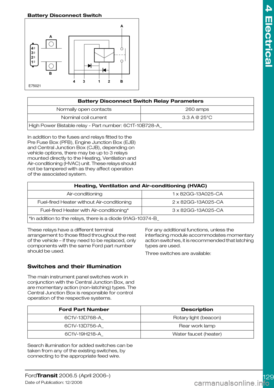
Battery Disconnect Switch
Battery Disconnect Switch Relay Parameters
260 ampsNormally open contacts
3.3 A @ 25°CNominal coil current
High Power Bistable relay - Part number: 6C1T-10B728-A_
In addition to the fuses and relays fitted to the
Pre Fuse Box (PFB), Engine Junction Box (EJB)
and Central Junction Box (CJB), depending on
vehicle options, there may be up to 3 relays
mounted directly to the Heating, Ventilation and
Air-conditioning (HVAC) unit. These relays should
not be tampered with as they affect operation
of the associated system.
Heating, Ventilation and Air-conditioning (HVAC)
1 x 82GG-13A025-CAAir-conditioning
2 x 82GG-13A025-CAFuel-fired Heater without Air-conditioning
3 x 82GG-13A025-CAFuel-fired Heater with Air-conditioning*
*In addition to the relays, there is a diode 91AG-10374-B_
These relays have a different terminal
arrangement to those fitted throughout the rest
of the vehicle – if they need to be replaced, only
components with the same Ford part number
should be used.
Switches and their Illumination
The main instrument panel switches work in
conjunction with the Central Junction Box, and
are momentary action (non-latching) types. The
Central Junction Box is responsible for control
operation of the respective systems.
For any additional functions, unless the
interfacing module accommodates momentary
action switches, it is recommended that latching
types are used.
Three switches are available:
DescriptionFord Part Number
Rotary light (beacon)6C1V-13D768-A_
Rear work lamp6C1V-13D756-A_
Water faucet (heater)6C1V-19H218-A_
Search illumination for added switches can be
taken from any of the existing switches, by
connecting to the appropriate feed wire.
FordTransit 2006.5 (April 2006–)
Date of Publication: 12/2006
4 Electrical
129E750211234AB4312BA
Page 137 of 234

Trailer Tow Connectivity - Trailer Tow, 12N & 12S Sockets
DescriptionItem
13N490 HarnessA
TubesX
PinsY
The Ford trailer tow system is designed to
support one primary set of direction indicators
installed on to the trailer (left hand side and right
hand side). If additional direction indicators are
required, for example for tall horse boxes, these
should be driven using separate relays with the
coils being energized via the respective primary
direction indicator feeds, and power to the bulbs
being derived from the KL30 (B+) line.
WARNING: Depending on the
vehicle's lighting configuration, the
Central Junction Box (CJB) will not
support trailer direction indicators
wired directly to the vehicle's
direction indicators. If this is
attempted, the relevant CJB circuits
may shut down or perform illegally.
The Central Junction Box (CJB) does not
support the incremental load of powering side
marker lamps on a trailer, if these are required
they should also be driven using separate relays,
as above.
NOTE: The trailer detect circuit is part of the
Ford Trailer Tow module – it is not implement
able separately – and is only operational on
vehicles fitted with power locking.
FordTransit 2006.5 (April 2006–)
Date of Publication: 12/2006
4 Electrical
137E8472241572634617325517113128131441516
Page 155 of 234

However, it is possible to add an additional lock(s)
– see also the section covering the ‘third button
on key fob’ – but only by utilizing relays (the
electric locks are operated by surface mounted
relays in the Central Junction Box – these are
only capable of powering one lock each, in
addition to which the output of these devices is
current-sensed to check it is within minimum and
maximum limits: I) to verify operation, and ii) as
part of the security system). For camper vehicles,
the Central Junction Box is configured for a
chassis cab vehicle.
Depending on functionality required, the pins
used will emulate the basic locking/unlocking
operation of an existing door. Note, however,
that any additional locks will not be covered by
the vehicle alarm or operate Central Junction
Box controlled lighting, etc. It would be necessary
to splice into either the Central Junction Box
connector or the in-line connector for the door
jumper harness. The coil of the relay (max.
300mA) should be added across the relevant
pin and ground (i.e. one relay for lock all, one
relay for driver door unlock etc.)
The use of Ford Transit lock mechanisms is
strongly recommended as the Central Junction
Box is designed to drive these latches for the
correct amount of time.
Function14A631 in-line
Passenger Side
14A631 in-line Drive
Side
Central Junc-
tion Box
Driver door unlock-6C2-7
Passenger door unlock (on
chassis Cab / Cab-Van Floor
only
6-C2-8
Deadlock all55C2-23
Lock all88C2-24
Locking Configurations- The following list
details specific locking scenarios that have been
noted by customers:
1.Raid locking or drive away locking for taxi and
parcel van usage – this is a configurable
parameter in the Central Junction Box (Ford
Dealerships can set this).
2.Slam locking – this is a configurable parameter
in Central Junction Box (marketing want to
sell this as an option, therefore dealerships
can only switch off this feature, but not switch
on).
3.N1 lock reconfiguration into M2 locking, i.e. no
deadlocks – this can be reconfigured to be
central-locking only by a Ford Dealer (via
Dealership hotline).
FordTransit 2006.5 (April 2006–)
Date of Publication: 12/2006
4 Electrical
155
Page 162 of 234

How to change the 3 pre-set default
RPM values in the 3 speed mode
1.Enter ‘learn mode’ (see directions above)
2.Arm the RPM speed controller (turn the key
switch to ‘on’)
3.Press & release the brake pedal once
4.Press & release the RPM button that requires
re-programming
5.Use the accelerator pedal to rev the engine to
the new desired RPM speed & hold at this
speed (only speeds between 1200 to 3000
rpm can be selected in 3 speed mode)
6.Press & release the same RPM button to reset
the stored RPM speed to the current engines
RPM
7.Release the accelerator pedal
8.Repeat steps 4) to 7) for the remaining RPM
buttons
The 3 RPM speeds should now be
re-programmed to the new RPM speeds. The
new settings can be saved & learn mode exited
(see below)
NOTE: If the engine RPM responds to the initial
RPM button press, then the vehicle has not
entered ‘learn mode’ correctly & you will have to
restart the procedure. If the engine stalls out at
the brake or accelerator pedal inputs then the
vehicle was not in, or has dropped out of ‘learn
mode’ & you will have to restart the procedure.
How to save new settings & exit
from ‘Learn mode’
1.From within the ‘learn mode’ & with the RPM
Speed Control switch box ‘armed’, press the
clutch pedal repeatedly until the engine stalls.
2.Restart the engine & test the new settings,
repeat above procedures if necessary
NOTE: The engine stalling indicates that the
settings should have been saved & the vehicle
has exited from ‘learn mode’. Learn mode
however is very specific that the exact steps are
taken in the correct order & within certain time
limits otherwise the learn procedure fails & it may
take several attempts to get this order & timing
correct & a successful modification from the
default settings.
Some Reasons why RPM speed
Control operation may stop or fail
The RPM Speed control software monitors
vehicle information during operation in RPM
speed control mode & will drop out of RPM speed
control and / or stall the engine should any
adverse signals be detected. For example:
•If the engine temperature becomes too hot
then RPM speed control will stop in order to
protect the engine.
•If the engine oil light illuminates then RPM
speed control will stop in order to protect the
engine
•If the low fuel level light illuminates then RPM
speed control will stop so that the vehicle can
be driven to a refueling point.
•If the vehicle speed exceeds approx 2.5 mph
wile in 3 speed or variable speed modes, then
RPM speed control may stop. RPM speed
control should normally be operated with the
hand brake on, but some uses may require a
low level of vehicle ‘creep’ during RPM speed
control operation. Note that there is no sensing
of the park brake on this version of RPM speed
controller to facilitate this type of operation.
•The software monitors for ‘stuck on’ buttons
on the control switch box, this may result in
RPM speed control being halted. A button that
is held down for too long may be registered
by the software as a ‘stuck’ button.
•The software monitors the foot pedals, if
depressed these may stall the engine if in 3
speed mode or variable speed mode (does
not apply to idle up speed)
•If the control switch box circuitry significantly
exceeds 2110 ohms or there is a short circuit
then RPM speed control will not be possible.
•If a PTO conversion has been attempted on a
vehicle with a non ABS braking system then
RPM speed control will fail due to vehicle
speed being registered via a transmission
speed sensor and / or the need to press the
clutch in order to put the vehicle in gear while
in RPM speed control mode.
4.14.10 Adding Connectors,
Terminals and Wiring
Additional Rear Speakers
NOTE: The connectors on the Instrument Panel
harness (14K024) and the main harness (14401)
are reversed between Left Hand Drive (LHD) and
Right Hand Drive (RHD) vehicles, hence different
sets of terminals/wires are required to cover all
the markets.
FordTransit 2006.5 (April 2006–)
Date of Publication: 12/2006
4 Electrical
162
Page 228 of 234

•It is recommended that the altered extension
has a similar closed section, material thickness
and properties to the existing chassis frame.
•An equivalent open section for the extension
assembly is at the vehicle converters
discretion.
•Lightening holes in new extension and cross
members are discretional.
•Do not weld original chassis frame except as
specified when adding reinforcing tubes,
please refer to Figure E745171.
•Do not drill the top or bottom surface of the
chassis frame, including the flanges turned
out, except as recommended above for
continuity of closure.
•Any alternative finish such as hot dip
galvanizing is at the discretion of the Body
Builder providing it does not have a detrimental
effect on the original Ford product.
Refer to: 5.10 Corrosion Prevention (page 221).
5.11.5 Frame Drilling and Tube
Reinforcing
The chassis frame may be drilled and reinforcing
spacer tubes may be welded in place, providing
the following is applied:
•Adhere to all details shown in Figure E74517.
•Drill and weld only side walls of the chassis
frame.
•Locate and drill holes accurately, using a drill
guide to ensure holes are square to frame
vertical centre line (note: allow for side member
draft angle).
•Drill undersize and ream out to size.
•Endeavor to remove all swarf from inside side
member, and treat to prevent corrosion.
•Fully weld each end of the tube and grind flat
and square, in groups if applicable. Be aware
of side member draft angle.
•Apply corrosion protection inside and outside
of the chassis frame.
Refer to: 5.10 Corrosion Prevention (page 221).
•Holes should be in groups of two (2), either
vertically spaced at 30 to 35mm from chassis
frame top and/or bottom surface, or
horizontally at 50mm minimum pitch, 30 to
35mm from top and/or bottom chassis frame
surface, please refer to Figure E74517.
•Always use M10 bolts with grade 8.8 minimum.
•Do not position tubes at the medium chassis
frame height, this may create “oil canning” of
the deep section side walls.
•Where possible, the outrigger moments should
be resolved by matching inner cross members
between the chassis side members inline with
the outriggers, please refer to Figure E74577-
Low Floor.
•A diameter of 16.5mm is the maximum
allowable hole size in the chassis frame side
wall, irrespective of the usage.
Avoid drilling into closed frame body members
to avoid the risk of corrosion from swarf.
Refer to: 5.10 Corrosion Prevention (page 221).
Drilling and welding of frames and body structure
have to be conducted following the program
guidelines. Please consult the Vehicle Converter
Advisory Service [email protected] for details.
5.11.6 Ancillary Equipment - Sub
Frame Mounting
Typical sub-frames and longitudinal members for
flatbed and low or drop-side bodies or equipment
exceeding the standard or Regular Production
Order frame length should adhere to the following
guidelines:
•Flat-beds and low bodies mounted on integral
longitudinal members (channel or box section
metal – not wood) must use both sides of all
frame mounting brackets, see Figure E74575.
•Longitudinal members must be relieved at the
front end if they are to contact the chassis
frame top surface, to minimize stress
concentrations, see Figure E74575. However,
it is preferable to mount the longitudinal onto
the mounting brackets, with a clearance to the
chassis frame top surface.
•Each set of brackets must use two (2) x M10
bolts grade 8.8 minimum.
•The rear two (2) sets of chassis frame
mounting holes / locations should have a full
bolt torque with 100% grip. The attachment to
the remaining forward chassis frame holes /
locations must be precisely located and
retained, but allow some relative flexing
between the sub-frame and chassis frame.
For example, clamp control devices such as
conical washer stacks or machine springs with
self locking fasteners.
•Minimum floor heights will require wheel arch
boxes to clear the rear tires, see Vehicle Data
sheets for relevant tire jounce.
•Chassis frame, for example: clamp control
devices such as conical washer stacks or
machine springs with self locking fastenings.
•Minimum floor heights will require wheel arch
boxes to clear the rear tires.
Pedestal mounted low or drop side bodies – (not
illustrated)
For bodies or equipment not exceeding the
standard or Regular Production Order chassis
frame length.
FordTransit 2006.5 (April 2006–)
Date of Publication: 12/2006
5 Body and Paint
228