Page 25 of 240

25
SAFETY
DEVICES
CORRECT USE
OF THE CAR
WARNING
LIGHTS AND
MESSAGES
IN AN
EMERGENCY
CAR
MAINTENANCE
TECHNICAL
SPECIFICATIONS
INDEX
DASHBOARD
AND CONTROLS
Audio info repetition (See Radio)
With this function the display repeats in-
formation relevant to the sound system.
– Radio: selected radio station frequency
or RDS message, automatic tuning acti-
vation or AutoSTore;
– audio CD, MP3 CD: track number;
– CD Changer: CD number and track
number;
– Tape: operating mode.
To activate (On) or to deactivate (Off)
sound system info displaying proceed as
follows:
– briefly press button MODE: (On) or
(Off)will flash on the display (according to
previous setting);
– press button +or –for setting;
– briefly press button MODEto go back
to the menu screen or press the button
for long to go back to the standard screen
without storing settings.Selecting door unlocking
With this function it is possible to decide
the door opening mode by selecting one
of the following options:
– open doors: to unlock all doors, except
the tailgate
– open driver’s door (op. drv. door): to
unlock just the driver’s door (where pro-
vided)
– open all: to unlock every door includ-
ing the tailgate
The car is delivered with this function in
“Open all” mode.
Proceed as follows:
– briefly press button MODE, the previ-
ous setting will flash on the display;
– press button +or –for setting;
– briefly press button MODEto go back
to the menu screen or press the button
for long to go back to the standard screen
without storing settings.Automatic central door locking
when travelling (Autoclose)
When activated (On), this function locks
automatically the doors when the car
speed exceeds 20 km/h.
To activate (On) or to deactivate (Off) this
function proceed as follows:
– briefly press button MODE: On or Off
will flash on the display (according to pre-
vious setting);
– press button +or –for setting;
– briefly press button MODEto go back
to the menu screen or press the button
for long to go back to the standard screen
without storing settings.
Units - “Distances” and
“Consumption”
With this function it is possible to set the
units for distance covered (km or mi).
To set the required unit proceed as fol-
lows:
– briefly press button MODE: km or mi
will flash on the display (according to pre-
vious setting);
001-030 Croma TRW GB 20-11-2006 14:58 Pagina 25
Page 26 of 240

26
SAFETY
DEVICES
CORRECT USE
OF THE CAR
WARNING
LIGHTS AND
MESSAGES
IN AN
EMERGENCY
CAR
MAINTENANCE
TECHNICAL
SPECIFICATIONS
INDEX
DASHBOARD
AND CONTROLS
– press button +or –for setting;
– briefly press button MODEto go back
to the menu screen or press the button
for long to go back to the standard screen
without storing settings.
If the distance unit set is km (see previous
paragraph) fuel consumption will be dis-
played in km/l or l/100km.
If the distance unit set is mi (see previous
paragraph) fuel consumption will be dis-
played in mpg.To set the required unit proceed as fol-
lows:
– briefly press button MODE: km/l or
l/100km will flash on the display (accord-
ing to previous setting);
– press button +or –for setting;
– briefly press button MODEto go back
to the menu screen or press the button
for long to go back to the standard screen
without storing settings.Selecting the language (Language)
Display messages can be shown in differ-
ent languages: Italian, English, German,
Portuguese, Spanish, French, Polish and
Dutch.
To set the required language proceed as
follows:
– briefly press button MODE: the previ-
ously set “language” will flash on the dis-
play;
– press button +or –for setting;
– briefly press button MODEto go back
to the menu screen or press the button
for long to go back to the standard screen
without storing settings.
001-030 Croma TRW GB 20-11-2006 14:58 Pagina 26
Page 27 of 240

27
SAFETY
DEVICES
CORRECT USE
OF THE CAR
WARNING
LIGHTS AND
MESSAGES
IN AN
EMERGENCY
CAR
MAINTENANCE
TECHNICAL
SPECIFICATIONS
INDEX
DASHBOARD
AND CONTROLS
Setting the buzzer volume
(Buzzer Volume)
With this function the volume of the
buzzer accompanying any failure/warning
indication can be adjusted according to 8
levels.
To set the required the volume proceed
as follows:
– briefly press button MODE: the previ-
ously set volume “level” will flash on the
display;
– press button +or –for setting;
– briefly press button MODEto go back
to the menu screen or press the button
for long to go back to the standard screen
without storing settings.Adjusting the button volume
(Button Vol.)
With this function the volume of the
roger-beep accompanying the activation
of buttons MODE, +and –can be ad-
justed according to 8 levels.
To set the required the volume proceed
as follows:
– briefly press button MODE: the previ-
ously set volume “level” will flash on the
display;
– press button +or –for setting;
– briefly press button MODEto go back
to the menu screen or press the button
for long to go back to the standard screen
without storing settings.Scheduled Servicing (Service)
Through this function it is possible to dis-
play information connected to proper car
servicing.
To display scheduled servicing info pro-
ceed as follows:
– briefly press button MODE: service in
km or mi, according to previous setting,
will be displayed (see paragraph “Distance
unit”);
– press button +or –to select displaying
in days;
– briefly press button MODEto go back
to the menu screen or press the button
for long to go back to the standard screen
without storing settings.
NoteThe “Service schedule” includes car
maintenance every 30,000 km (or 18,000
mi); this is shown automatically, with the
ignition key at ON, starting from 2,000 km
(or 1,240 mi) from this deadline and it is
shown again every 200 km (or 124 mi).
When a scheduled service interval
(“coupon”) is near to come, turning the
ignition key to ON, will display the mes-
sage “Service” followed by the number of
km to go before car servicing and symbol
õ. “Service” message is displayed in kilo-
metres (km) or miles (mi), according to
the setting chosen previously. Contact Fi-
001-030 Croma TRW GB 20-11-2006 14:58 Pagina 27
Page 28 of 240

28
SAFETY
DEVICES
CORRECT USE
OF THE CAR
WARNING
LIGHTS AND
MESSAGES
IN AN
EMERGENCY
CAR
MAINTENANCE
TECHNICAL
SPECIFICATIONS
INDEX
DASHBOARD
AND CONTROLS
at Dealership to carry out any service op-
eration provided by the “Service sched-
ule” or “Annual inspection plan”, and to
reset the display.
Exit Menu
This is the last function that closes the cir-
cular setting cycle listed in the initial menu
screen.
Briefly press button MODEto go back to
the standard screen without storing set-
tings.
Press button –to return to the first menu
option (Speed Lim.).Both functions are resettable (reset - start
of new mission).
“General Trip” displays the figures relat-
ing to:
– Range
– Trip distance
– Average consumption
– Instant consumption
– Average speed
– Travel time (driving time).
“Trip B” (only available on reconfigurable
multifunction display), displays the figures
relating to:
– Trip distance B
– Average consumption B
– Average speed B
– Travel time B (driving time).
NoteThe “Trip B” function can be ex-
cluded (see paragraph “Trip B On/Off”).
“Range” cannot be reset.TRIP COMPUTER
(where provided)
General features
The “Trip computer” is provided on cars
fitted with multifunction display or re-
configurable multifunction display. The
“Trip computer” displays information
(with ignition key at ON), relating to the
operating status of the car. This function
comprises the “General trip” concerning
the “complete mission” of the car (jour-
ney) and “Trip B”, (only available on re-
configurable multifunction display), con-
cerning the partial mission of the car; this
latter function(as shown in fig. 26) is “con-
tained” within the complete mission.
001-030 Croma TRW GB 20-11-2006 14:58 Pagina 28
Page 29 of 240

29
SAFETY
DEVICES
CORRECT USE
OF THE CAR
WARNING
LIGHTS AND
MESSAGES
IN AN
EMERGENCY
CAR
MAINTENANCE
TECHNICAL
SPECIFICATIONS
INDEX
DASHBOARD
AND CONTROLS
Values displayed
Range
This value shows the distance in km (or
mi) that the car can still cover before
needing fuel, assuming that driving condi-
tions are kept unvaried. The display will
show “----” in the following cases:
– value lower than 50 km (or 30 mi)
– car left parked with engine running for
long.
Trip distance
This value shows the distance covered
from the start of the new mission.
Average consumption
This value shows the average consump-
tion from the start of the new mission.
Instant consumption
This value shows instant fuel consumption
(this value is updated second by second).
If parking the car with engine on,
the display will show “----”.Average speed
This value shows the car average speed as
a function of the overall time elapsed since
the start of the new mission.
Travel time
This value shows the time elapsed since
the start of the new mission.
IMPORTANT Lacking information, Trip
computer values are displayed with “----”.
When normal operating condition is re-
set, calculation of different units will
restart regularly. Values displayed before
the failure will not be reset.TRIP button fig. 25
Button TRIP, set on the top of the right
steering column stalk, shall be used (with
ignition key at ON) to display and to re-
set the previously described values to start
a new mission:
– short push to display the different val-
ues
– long push to reset and then start a new
mission.
New mission
New mission starts after:
– “manual” resetting by the user, by press-
ing the relevant button;
– “automatic” resetting, when the “Trip dis-
tance” reaches 9999.9 km or when the
“Travel time” reaches 99.59 (99 hours and
59 minutes);
– after disconnecting/reconnecting the
battery.
001-030 Croma TRW GB 20-11-2006 14:58 Pagina 29
Page 30 of 240

30
SAFETY
DEVICES
CORRECT USE
OF THE CAR
WARNING
LIGHTS AND
MESSAGES
IN AN
EMERGENCY
CAR
MAINTENANCE
TECHNICAL
SPECIFICATIONS
INDEX
DASHBOARD
AND CONTROLS
IMPORTANT The reset operation in the
presence of the screens concerning the
“General Trip” makes it possible to reset
also the “Trip B”. The reset operation in
the presence of the screens concerning
only the “Trip B” makes it possible to re-
set only the information associated with
this function.Start of journey procedure
With ignition key at ON, press and keep
button TRIPpressed for over 2 seconds
to reset.
F0L0070mfig. 25
Reset TRIP B
End of partial mission
Start of new partial mission
End of partial mission
Start of new
partial mission
Reset TRIP B
End of partial mission
Start of new
partial mission Reset GENERAL TRIP
End of complete mission
Start of new missionReset GENERAL TRIP
End of complete mission
Start of new mission
End of partial mission
Start of new
partial mission Reset TRIP B
Reset TRIP B
TRIP B
TRIP B
TRIP B GENERAL TRIP˙
˙
˙
˙˙
˙
˙ ˙
fig. 26
001-030 Croma TRW GB 20-11-2006 14:58 Pagina 30
Page 31 of 240

SEATS
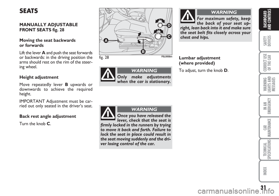
MANUALLY ADJUSTABLE
FRONT SEATS fig. 28
Moving the seat backwards
or forwards
Lift the lever Aand push the seat forwards
or backwards: in the driving position the
arms should rest on the rim of the steer-
ing wheel.
Height adjustment
Move repeatedly lever Bupwards or
downwards to achieve the required
height.
IMPORTANT Adjustment must be car-
ried out only seated in the driver’s seat.
Back rest angle adjustment
Turn the knob C.
31
SAFETY
DEVICES
CORRECT USE
OF THE CAR
WARNING
LIGHTS AND
MESSAGES
IN AN
EMERGENCY
CAR
MAINTENANCE
TECHNICAL
SPECIFICATIONS
INDEX
DASHBOARD
AND CONTROLS
fig. 28F0L0008m
For maximum safety, keep
the back of your seat up-
right, lean back into it and make sure
the seat belt fits closely across your
chest and hips.
WARNING
Only make adjustments
when the car is stationary.
WARNING
Once you have released the
lever, check that the seat is
firmly locked in the runners by trying
to move it back and forth. Failure to
lock the seat in place could result in
the seat moving suddenly and the dri-
ver losing control of the car.
WARNING
Lumbar adjustment
(where provided)
To adjust, turn the knob D.
Page 32 of 240
Seat warming fig. 30
With ignition key at ON, press button F
to switch the seat warming on/off. The led
on the button will light up when the func-
tion is on.
32
SAFETY
DEVICES
CORRECT USE
OF THE CAR
WARNING
LIGHTS AND
MESSAGES
IN AN
EMERGENCY
CAR
MAINTENANCE
TECHNICAL
SPECIFICATIONS
INDEX
DASHBOARD
AND CONTROLS
Tilting the back rest
(where provided) fig. 29
Move repeatedly lever Eupwards or
downwards to achieve the required po-
sition.
IMPORTANT Adjustment must be car-
ried out only seated in the driver’s seat.
fig. 29F0L0136mfig. 30F0L0199mfig. 31F0L0104m
Front passenger’s seat “table”
tilting (where provided) fig. 31
To tilt the seat, lift lever Aand fold the
back rest at the same time.
To reset it to normal position, operate
lever Aand at the same time raise the
back rest until hearing the coupling/lock-
ing click.