Page 3759 of 5267
P1757-GOV PRESS ABOVE 3 PSI IN GEAR WITH 0 MPH (DIESEL)
For a complete wiring diagramRefer to Section 8W
Page 3765 of 5267
P1762-GOV PRESS SENSOR OFFSET VOLTS TOO LOW OR HIGH (DIESEL)
For a complete wiring diagramRefer to Section 8W
Page 3770 of 5267
P2769-TRANSMISSION TCC CONTROL CIRCUIT LOW
For a complete wiring diagramRefer to Section 8W
Page 3777 of 5267
P2770-TRANSMISSION TCC CONTROL CIRCUIT HIGH (DIESEL)
For a complete wiring diagramRefer to Section 8W
Page 3782 of 5267
*TOW /HAUL OVERDRIVE OFF SWITCH (DIESEL)
For a complete wiring diagramRefer to Section 8W
Page 3786 of 5267

PRE-DIAGNOSTIC CHECKOUT (DIESEL)
For a complete wiring diagramRefer to Section 8W
1.PRE-DIAGNOSTIC CHECKOUT
NOTE: Always perform diagnostics with a fully charged battery to avoid false symptoms.
NOTE: Low fluid level can be the cause of many transmission problems. If thefluid level is low locate and
repair the leak then check and adjust the fluid level per the Service Information.
With the scan tool, read engine DTC’s. Check and repair all engine DTCs prior to performing transmission symptom
diagnostics.
Using the wiring diagram/schematic as a guide, inspect the wiring and connectors. Repair as necessary.
Verify the flash level of the Engine Control Module. Some problems are corrected by software upgrades.
Check for any Service Information Tune-ups or Technical Service Bulletins that may apply.
Did any of the above checks or procedures correct the symptom?
Ye s>>
Repair is complete.
Perform RE TRANSMISSION VERIFICATION TEST VER - 1 (DIESEL). (Refer to 21 - TRANSMISSION/
TRANSAXLE/AUTOMATIC - 48RE - STANDARD PROCEDURE)
No>>
Refer to the Transmission category and perform the appropriate symptom(s).
Page 4022 of 5267
C1401- TRANSFER CASE RANGE SELECT SWITCH CIRCUIT LOW
For a complete wiring diagramRefer to Section 8W
Page 4026 of 5267

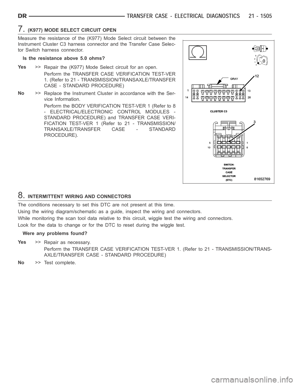
7.(K977) MODE SELECT CIRCUIT OPEN
Measure the resistance of the (K977) Mode Select circuit between the
Instrument Cluster C3 harness connector and the Transfer Case Selec-
tor Switch harness connector.
Is the resistance above 5.0 ohms?
Ye s>>
Repair the (K977) Mode Select circuit for an open.
Perform the TRANSFER CASE VERIFICATION TEST-VER
1. (Refer to 21 - TRANSMISSION/TRANSAXLE/TRANSFER
CASE - STANDARD PROCEDURE)
No>>
Replace the Instrument Cluster in accordance with the Ser-
vice Information.
Perform the BODY VERIFICATION TEST-VER 1 (Refer to 8
- ELECTRICAL/ELECTRONIC CONTROL MODULES -
STANDARD PROCEDURE) and TRANSFER CASE VERI-
FICATION TEST-VER 1 (Refer to 21 - TRANSMISSION/
TRANSAXLE/TRANSFER CASE - STANDARD
PROCEDURE).
8.INTERMITTENT WIRING AND CONNECTORS
The conditions necessary to set this DTC are not present at this time.
Using the wiring diagram/schematic as a guide, inspect the wiring and connectors.
While monitoring the scan tool data relative to this circuit, wiggle test the wiring and connectors.
Look for the data to change or for the DTC to reset during the wiggle test.
Were any problems found?
Ye s>>
Repair as necessary.
Perform the TRANSFER CASE VERIFICATION TEST-VER 1. (Refer to 21 - TRANSMISSION/TRANS-
AXLE/TRANSFER CASE - STANDARD PROCEDURE)
No>>
Te s t c o m p l e t e .