Page 1217 of 5267
8.FUEL INJECTOR OPERATION
WARNING: The fuel system is under a constant pressure (even with the engineoff). Before testing or ser-
vicing any fuel system hose, fitting or line, the fuel system pressure mustbe released. Failure to follow
these instructions can result in personal injury or death.
CAUTION: After each Fuel Injector actuation, start the engine to clean thecylinder of fuel. Failure to do so
could cause engine damage.
Remove special tool #C4390.
Start the engine and allow the fuel pressure to reach maximum pressure.
Ignition on, engine not running.
Using the scan tool, actuate the Fuel Injector.
Monitor the fuel pressure gauge.
Does the fuel pressure gauge indicate a drop in fuel pressure?
Ye s>>
Go To 9
No>>
Go To 10
NOTE: Turn the ignition off, remove the Fuel Pressure gauge, and connect the fuel lines before continuing.
9.ENGINE MECHANICAL
Check for any of the following conditions/mechanical problems.
ENGINE VACUUM - must be at least 13 inches in neutral
ENGINE VALVE TIMING - must be within specifications
ENGINE COMPRESSION - must be within specifications
ENGINE EXHAUST SYSTEM - must be free of any restrictions or leaks.
ENGINE PCV SYSTEM - must flow freely
TORQUE CONVERTER STALL SPEED - must be within specifications
POWER BRAKE BOOSTER - no internal vacuum leaks
FUEL - must be free of contamination
CAM LOBES - must not be worn excessively
CYLINDER LEAKAGE TEST - must be within specifications
VALVE SPRINGS - cannot be weak or broken
Are there any engine mechanical problems?
Ye s>>
Repair as necessary.
Perform the POWERTRAIN VERIFICATION TEST. (Refer to 9 - ENGINE - STANDARD PROCEDURE)
No>>
Go To 17
Page 1218 of 5267
10.FUEL INJECTOR
Turn the ignition off.
Disconnect the Fuel Injector harness connector.
Ignition on, engine not running.
NOTE: When a Misfire is detected for a particular cylinder, the PCM
will shut down that cylindersInjector Control circuit.
With the scan tool, erase DTCs.
Using a 12-volt test light connected to 12-volts, probe the (K116) Injec-
tor Control circuit.
With the scan tool, actuate the Fuel Injector.
Does the test light blink/flicker?
Ye s>>
Replace the Fuel Injector.
Perform the POWERTRAIN VERIFICATION TEST. (Refer to
9 - ENGINE - STANDARD PROCEDURE)
No>>
Go To 11
11 .INJECTOR CONTROL CIRCUIT
Turn the ignition off.
Disconnect the PCM harness connector.
Check the Injector Control circuit for an open or short to ground.
Was a problem found with the Injector Control circuit?
Ye s>>
Repair the excessive resistance or short in the Injector Con-
trol circuit.
Perform the POWERTRAIN VERIFICATION TEST. (Refer to
9 - ENGINE - STANDARD PROCEDURE)
No>>
Go To 17
Page 1219 of 5267
12.FUEL SUPPLY LINE RESTRICTED
Turn the ignition off.
WARNING: The fuel system is under a constant pressure (even with the engineoff). Before testing or ser-
vicing any fuel system hose, fitting or line, the fuel system pressure mustbe released. Failure to follow
these instructions can result in personal injury or death.
Raise vehicle on hoist, and disconnect the fuel pressure line at the fuel pump module.
Install special tool #6539 (5/16
) #6631(3/8) fuel line adapter and the fuel pressure gauge between the fuel supply
line and the fuel pump module.
Ignition on, engine not running.
With the scan tool, actuate the ASD FuelSystem test and observe the fuel pressure gauge.
NOTE: Fuel pressure specification is 379 KPa +/- 14 KPa (55 psi +/- 2 psi).
Is the fuel pressure within specification?
Ye s>>
Repair or replace fuel supply line as necessary.
Perform the POWERTRAIN VERIFICATION TEST. (Refer to 9 - ENGINE - STANDARD PROCEDURE)
No>>
Go To 13
13.FUEL PUMP INLET STRAINER
Turn the ignition off.
WARNING: The fuel system is under a constant pressure (even with the engineoff). Before testing or ser-
vicing any fuel system hose, fitting or line, the fuel system pressure mustbe released. Failure to follow
these instructions can result in personal injury or death.
Remove the Fuel Pump Module and inspect the Fuel Inlet Strainer.
Is the Fuel Inlet Strainer plugged?
Ye s>>
Replace the Fuel Pump Inlet Strainer.
Perform the POWERTRAIN VERIFICATION TEST. (Refer to 9 - ENGINE - STANDARD PROCEDURE)
No>>
Before continuing, check the Fuel Pump Module harness connector terminals for corrosion, damage, or
terminal push out. Make sure the ground circuit is functional. Repair as necessary. Replace the Fuel
Pump Module.
Perform the POWERTRAIN VERIFICATION TEST. (Refer to 9 - ENGINE - STANDARD PROCEDURE)
14.IGNITION WIRE
NOTE: If the vehicle being tested does not have an ignition wire answer YES to this test and continue.
Turn the ignition off.
Remove the ignition wire.
Measure the resistance of the ignition wire.
Is the resistance below 10K ohms?
Ye s>>
Go To 15
No>>
Replace the Ignition Wire.
Perform the POWERTRAIN VERIFICATION TEST. (Refer to 9 - ENGINE - STANDARD PROCEDURE)
Page 1220 of 5267
15.IGNITION COIL
Disconnect the Ignition Coil harness connector.
Remove the Fuel Pump Relay.
Using a 12-volt test light connected to 12-volts, probe the (K17) Coil
Control circuit.
Crank the engine for 5 seconds while observing the test light.
NOTE: The primary resistance of the 8.3L Ignition coil is 0.53 to
0.65 of an ohm at 77°F (25°C).
Does the test light brightly blink/flicker?
Ye s>>
Replace the Ignition Coil.
Perform the POWERTRAIN VERIFICATION TEST. (Refer to
9 - ENGINE - STANDARD PROCEDURE)
No>>
Go To 16
16.COIL CONTROL CIRCUIT
Turn the ignition off.
Disconnect the PCM harness connector.
Check the (K17) Coil Control circuit for an open or short to ground.
Was a problem found with the Coil Control circuit?
Ye s>>
Repair the Coil Control circuit.
Perform the POWERTRAIN VERIFICATION TEST. (Refer to
9 - ENGINE - STANDARD PROCEDURE)
No>>
Go To 17
Page 1221 of 5267
17.PCM
NOTE: Before continuing, check the PCM harness connector terminals for corrosion, damage, or terminal
push out. Repair as necessary.
Using the schematics as a guide, inspect the wire harness and connectors. Pay particular attention to all Power and
Ground circuits.
Were there any problems found?
Ye s>>
Repair as necessary.
Perform the POWERTRAIN VERIFICATION TEST. (Refer to 9 - ENGINE - STANDARD PROCEDURE)
No>>
Replace and program the Powertrain Control Module per Service Information.
Perform the POWERTRAIN VERIFICATION TEST. (Refer to 9 - ENGINE - STANDARD PROCEDURE)
Page 1228 of 5267
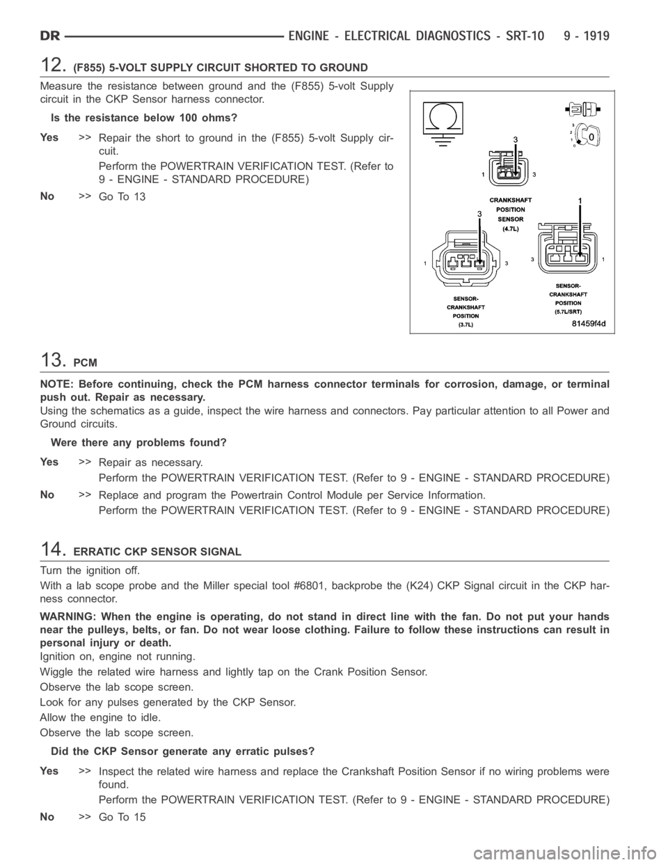
12.(F855) 5-VOLT SUPPLY CIRCUIT SHORTED TO GROUND
Measure the resistance between ground and the (F855) 5-volt Supply
circuit in the CKP Sensor harness connector.
Istheresistancebelow100ohms?
Ye s>>
Repair the short to ground in the (F855) 5-volt Supply cir-
cuit.
Perform the POWERTRAIN VERIFICATION TEST. (Refer to
9 - ENGINE - STANDARD PROCEDURE)
No>>
Go To 13
13.PCM
NOTE: Before continuing, check the PCM harness connector terminals for corrosion, damage, or terminal
push out. Repair as necessary.
Using the schematics as a guide, inspect the wire harness and connectors. Pay particular attention to all Power and
Ground circuits.
Were there any problems found?
Ye s>>
Repair as necessary.
Perform the POWERTRAIN VERIFICATION TEST. (Refer to 9 - ENGINE - STANDARD PROCEDURE)
No>>
Replace and program the Powertrain Control Module per Service Information.
Perform the POWERTRAIN VERIFICATION TEST. (Refer to 9 - ENGINE - STANDARD PROCEDURE)
14.ERRATIC CKP SENSOR SIGNAL
Turn the ignition off.
With a lab scope probe and the Miller special tool #6801, backprobe the (K24) CKP Signal circuit in the CKP har-
ness connector.
WARNING: When the engine is operating, do not stand in direct line with the fan. Do not put your hands
near the pulleys, belts, or fan. Do notwear loose clothing. Failure to follow these instructions can result in
personal injury or death.
Ignition on, engine not running.
Wiggle the related wire harness and lightly tap on the Crank Position Sensor.
Observe the lab scope screen.
Look for any pulses generated by the CKP Sensor.
Allow the engine to idle.
Observe the lab scope screen.
Did the CKP Sensor generate any erratic pulses?
Ye s>>
Inspect the related wire harness and replace the Crankshaft Position Sensor if no wiring problems were
found.
Perform the POWERTRAIN VERIFICATION TEST. (Refer to 9 - ENGINE - STANDARD PROCEDURE)
No>>
Go To 15
Page 1233 of 5267
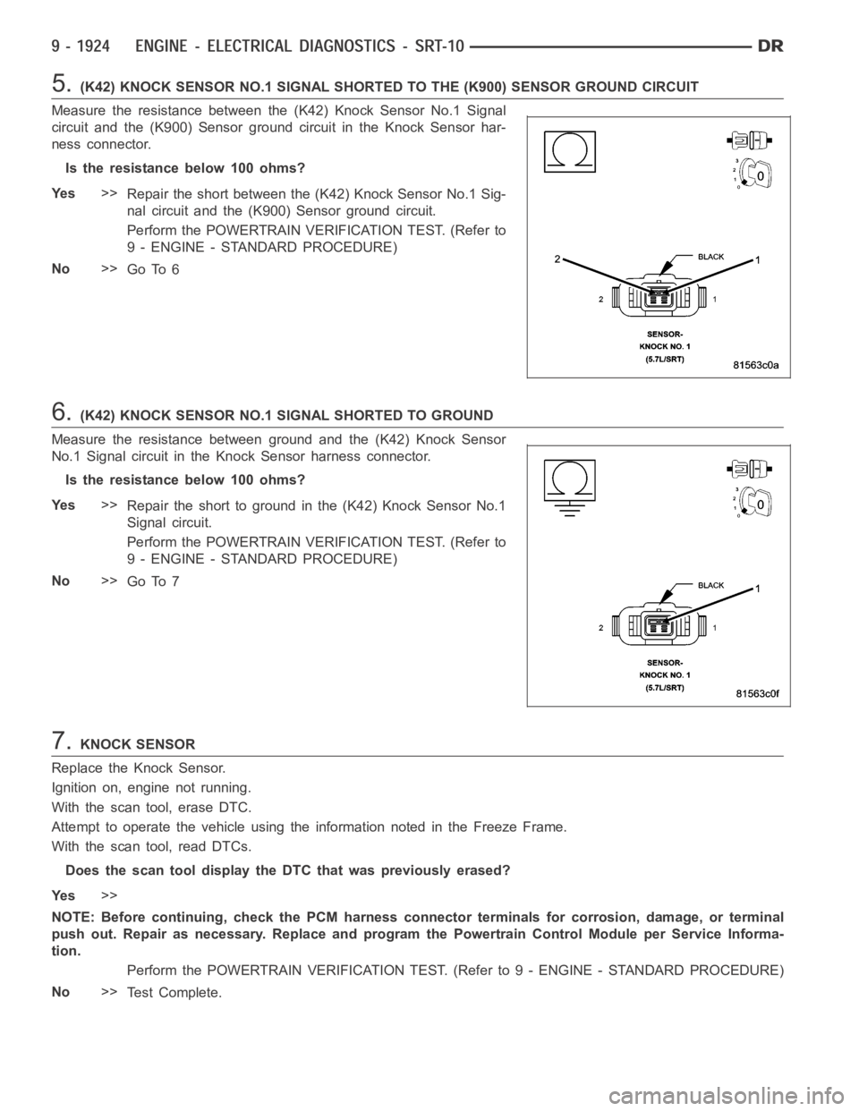
5.(K42) KNOCK SENSOR NO.1 SIGNAL SHORTED TO THE (K900) SENSOR GROUND CIRCUIT
Measure the resistance between the (K42) Knock Sensor No.1 Signal
circuit and the (K900) Sensor ground circuit in the Knock Sensor har-
ness connector.
Istheresistancebelow100ohms?
Ye s>>
Repair the short between the (K42) Knock Sensor No.1 Sig-
nal circuit and the (K900) Sensor ground circuit.
Perform the POWERTRAIN VERIFICATION TEST. (Refer to
9 - ENGINE - STANDARD PROCEDURE)
No>>
Go To 6
6.(K42) KNOCK SENSOR NO.1 SIGNAL SHORTED TO GROUND
Measure the resistance between ground and the (K42) Knock Sensor
No.1 Signal circuit in the Knock Sensor harness connector.
Istheresistancebelow100ohms?
Ye s>>
Repair the short to ground in the (K42) Knock Sensor No.1
Signal circuit.
Perform the POWERTRAIN VERIFICATION TEST. (Refer to
9 - ENGINE - STANDARD PROCEDURE)
No>>
Go To 7
7.KNOCK SENSOR
Replace the Knock Sensor.
Ignition on, engine not running.
With the scan tool, erase DTC.
Attempt to operate the vehicle using the information noted in the Freeze Frame.
With the scan tool, read DTCs.
Does the scan tool display the DTC that was previously erased?
Ye s>>
NOTE: Before continuing, check the PCM harness connector terminals for corrosion, damage, or terminal
push out. Repair as necessary. Replace and program the Powertrain ControlModule per Service Informa-
tion.
Perform the POWERTRAIN VERIFICATION TEST. (Refer to 9 - ENGINE - STANDARD PROCEDURE)
No>>
Te s t C o m p l e t e .
Page 1237 of 5267
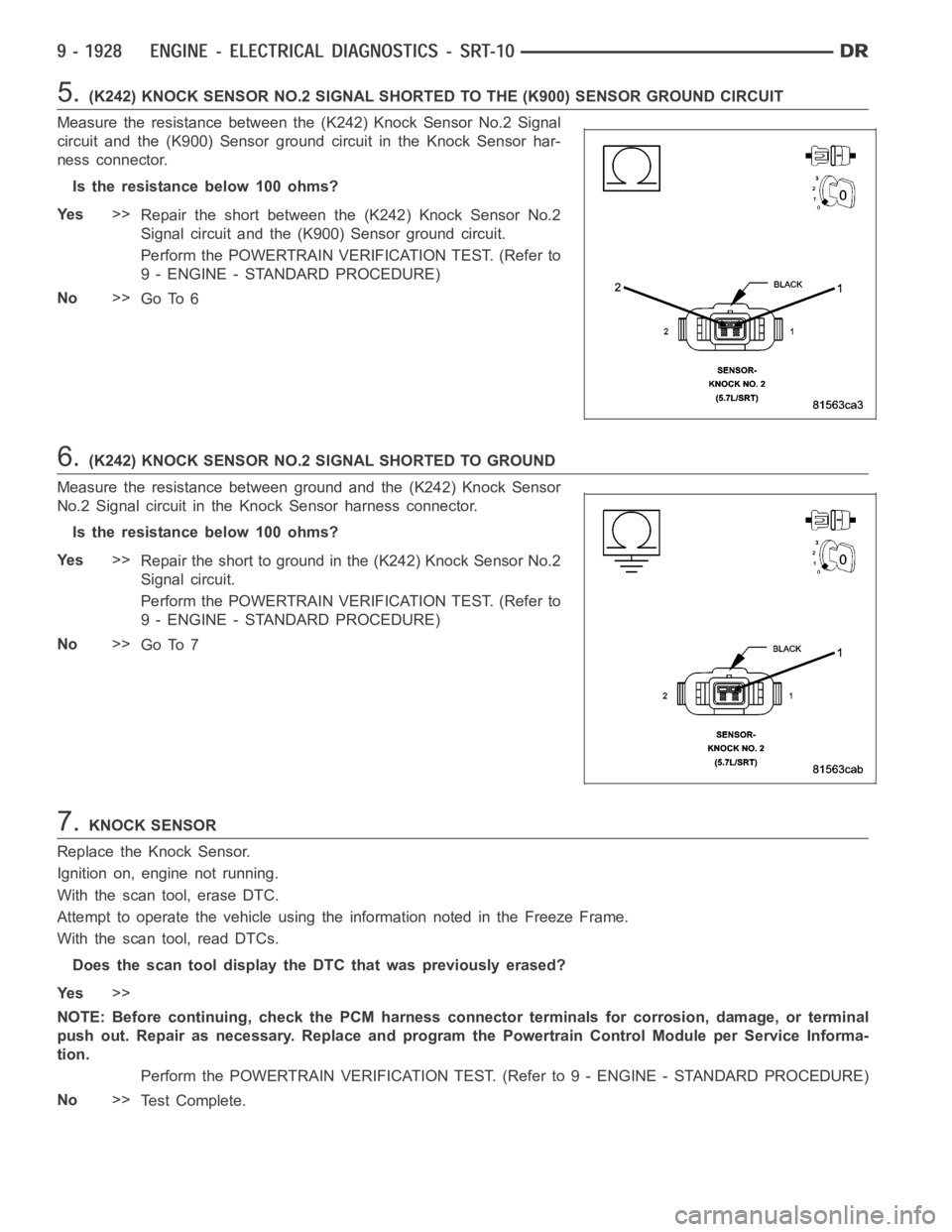
5.(K242) KNOCK SENSOR NO.2 SIGNAL SHORTED TO THE (K900) SENSOR GROUND CIRCUIT
Measure the resistance between the (K242) Knock Sensor No.2 Signal
circuit and the (K900) Sensor ground circuit in the Knock Sensor har-
ness connector.
Istheresistancebelow100ohms?
Ye s>>
Repair the short between the (K242) Knock Sensor No.2
Signal circuit and the (K900) Sensor ground circuit.
Perform the POWERTRAIN VERIFICATION TEST. (Refer to
9 - ENGINE - STANDARD PROCEDURE)
No>>
Go To 6
6.(K242) KNOCK SENSOR NO.2 SIGNAL SHORTED TO GROUND
Measure the resistance between ground and the (K242) Knock Sensor
No.2 Signal circuit in the Knock Sensor harness connector.
Istheresistancebelow100ohms?
Ye s>>
Repair the short to ground in the (K242) Knock Sensor No.2
Signal circuit.
Perform the POWERTRAIN VERIFICATION TEST. (Refer to
9 - ENGINE - STANDARD PROCEDURE)
No>>
Go To 7
7.KNOCK SENSOR
Replace the Knock Sensor.
Ignition on, engine not running.
With the scan tool, erase DTC.
Attempt to operate the vehicle using the information noted in the Freeze Frame.
With the scan tool, read DTCs.
Does the scan tool display the DTC that was previously erased?
Ye s>>
NOTE: Before continuing, check the PCM harness connector terminals for corrosion, damage, or terminal
push out. Repair as necessary. Replace and program the Powertrain ControlModule per Service Informa-
tion.
Perform the POWERTRAIN VERIFICATION TEST. (Refer to 9 - ENGINE - STANDARD PROCEDURE)
No>>
Te s t C o m p l e t e .