Page 4459 of 5267
FLARE MOLDING-FRONT WHEEL OPENING
REMOVAL
1. Remove the push-pin (1) and six screws (2).
2. Remove the flare (1).
Page 4461 of 5267
FLARE MOLDING-REAR WHEEL OPENING
REMOVAL
1. Remove the push-pin (1) and six screws (2).
2. Remove the flare (1).
Page 4467 of 5267

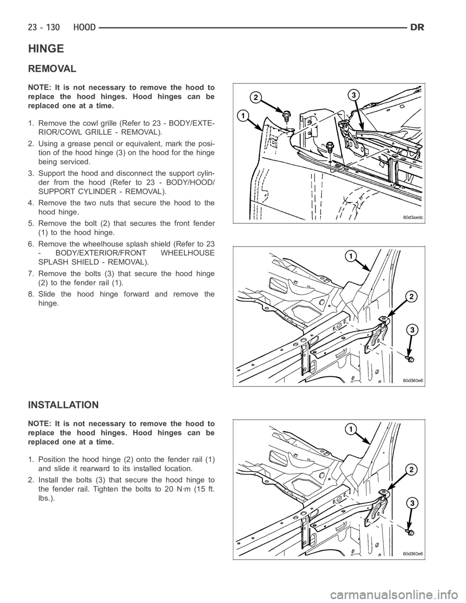
HINGE
REMOVAL
NOTE: It is not necessary to remove the hood to
replace the hood hinges. Hood hinges can be
replaced one at a time.
1. Remove the cowl grille (Refer to 23 - BODY/EXTE-
RIOR/COWL GRILLE - REMOVAL).
2. Using a grease pencil or equivalent, mark the posi-
tion of the hood hinge (3) on the hood for the hinge
being serviced.
3. Support the hood and disconnect the support cylin-
der from the hood (Refer to 23 - BODY/HOOD/
SUPPORT CYLINDER - REMOVAL).
4. Remove the two nuts that secure the hood to the
hood hinge.
5. Remove the bolt (2) that secures the front fender
(1) to the hood hinge.
6. Remove the wheelhouse splash shield (Refer to 23
- BODY/EXTERIOR/FRONT WHEELHOUSE
SPLASH SHIELD - REMOVAL).
7. Remove the bolts (3) that secure the hood hinge
(2) to the fender rail (1).
8. Slide the hood hinge forward and remove the
hinge.
INSTALLATION
NOTE: It is not necessary to remove the hood to
replace the hood hinges. Hood hinges can be
replaced one at a time.
1. Position the hood hinge (2) onto the fender rail (1)
and slide it rearward to its installed location.
2. Install the bolts (3) that secure the hood hinge to
the fender rail. Tighten the bolts to 20 Nꞏm (15 ft.
lbs.).
Page 4468 of 5267
3. Install the bolt (2) that secures the front fender (1)
to the hood hinge (3). Tighten the bolt to 12.5 Nꞏm
(9 ft. lbs.).
4. Loosely install the two nuts that secure the hood to
the hood hinge.
5. Align the hood to the hood hinge using the refer-
ence marks made during the Removal procedure
and tighten the nuts to 23 Nꞏm (17 ft. lbs.).
6. Install the support cylinder (Refer to 23 - BODY/
HOOD/SUPPORT CYLINDER - INSTALLATION).
7. If required, adjust the hood to the correct position
(Refer to 23 - BODY/BODY STRUCTURE/GAP
AND FLUSH - SPECIFICATIONS).
8. Install the wheelhouse splash shield (Refer to 23 -
BODY/EXTERIOR/FRONT WHEELHOUSE
SPLASH SHIELD - INSTALLATION).
9. Install the cowl grille (Refer to 23 - BODY/EXTERIOR/COWL GRILLE - INSTALLATION).
Page 4476 of 5267

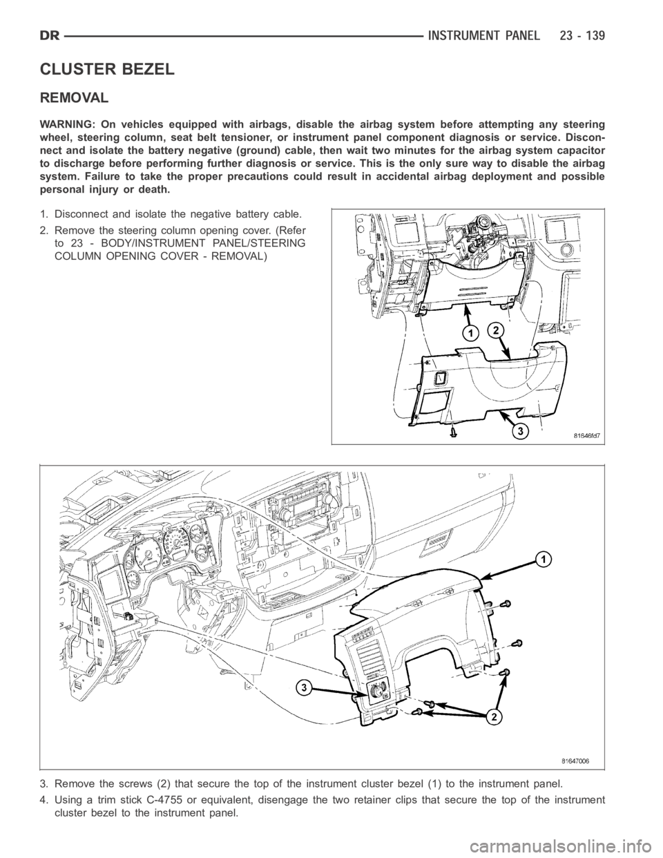
CLUSTER BEZEL
REMOVAL
WARNING: On vehicles equipped with airbags, disable the airbag system before attempting any steering
wheel, steering column, seat belt tensioner, or instrument panel component diagnosis or service. Discon-
nect and isolate the battery negative (ground) cable, then wait two minutes for the airbag system capacitor
to discharge before performing further diagnosis or service. This is the only sure way to disable the airbag
system. Failure to take the proper precautions could result in accidentalairbag deployment and possible
personal injury or death.
1. Disconnect and isolate the negative battery cable.
2. Remove the steering column opening cover. (Refer
to 23 - BODY/INSTRUMENT PANEL/STEERING
COLUMN OPENING COVER - REMOVAL)
3. Remove the screws (2) that secure the top of the instrument cluster bezel(1) to the instrument panel.
4. Using a trim stick C-4755 or equivalent, disengage the two retainer clips that secure the top of the instrument
cluster bezel to the instrument panel.
Page 4484 of 5267
INSTRUMENT PANEL ASSEMBLY
REMOVAL
WARNING: On vehicles equipped with airbags, disable the airbag system before attempting any steering
wheel, steering column, seat belt tensioner, or instrument panel component diagnosis or service. Discon-
nect and isolate the battery negative (ground) cable, then wait two minutes for the airbag system capacitor
to discharge before performing further diagnosis or service. This is the only sure way to disable the airbag
system. Failure to take the proper precautions could result in accidentalairbag deployment and possible
personal injury or death.
1. Disconnect and isolate the negative battery cable.
2. Remove the left a-pillar trim (Refer to 23 - BODY/
INTERIOR/A-PILLAR TRIM/GRAB HANDLE -
REMOVAL).
3. Disconnect the headliner wire harness connector
located at the a-pillar.
4. Remove the instrument panel top cover (Refer to
23 - BODY/INSTRUMENT PANEL/INSTRUMENT
PANEL TOP COVER - REMOVAL).
Page 4501 of 5267
INSTRUMENT PANEL CENTER BEZEL
REMOVAL
WARNING: On vehicles equipped with airbags, disable the airbag system before attempting any steering
wheel, steering column, seat belt tensioner, or instrument panel component diagnosis or service. Discon-
nect and isolate the battery negative (ground) cable, then wait two minutes for the airbag system capacitor
to discharge before performing further diagnosis or service. This is the only sure way to disable the airbag
system. Failure to take the proper precautions could result in accidentalairbag deployment and possible
personal injury or death.
1. Disconnect and isolate the negative battery cable.
2. Using a trim stick C-4755 or equivalent, disengage
the retainer clips that secure the instrument panel
center bezel to the instrument panel.
3. Disconnect the wire harness connectors and
remove the center bezel from the vehicle.
Page 4503 of 5267

INSTRUMENT PANEL DRIVER SIDE BEZEL
REMOVAL
WARNING: On vehicles equipped with airbags, disable the airbag system before attempting any steering
wheel, steering column, seat belt tensioner, or instrument panel component diagnosis or service. Discon-
nect and isolate the battery negative (ground) cable, then wait two minutes for the airbag system capacitor
to discharge before performing further diagnosis or service. This is the only sure way to disable the airbag
system. Failure to take the proper precautions could result in accidentalairbag deployment and possible
personal injury or death.
1. Disconnect and isolate the negative battery cable.
2. Using a trim stick C-4755 or equivalent, from the
notch on the bottom, remove the left instrument
panel side cover.
3. Remove the left cowl trim panel (Refer to 23 -
BODY/INTERIOR/COWL TRIM - REMOVAL).
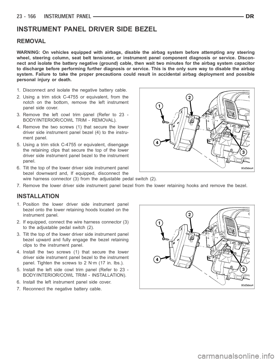
4. Remove the two screws (1) that secure the lower
driver side instrument panel bezel (4) to the instru-
ment panel.
5. Using a trim stick C-4755 or equivalent, disengage
the retaining clips that secure the top of the lower
driver side instrument panel bezel to the instrument
panel.
6. Tilt the top of the lower driver side instrument panel
bezel downward and, If equipped, disconnect the
wire harness connector (3) from the adjustable pedal switch (2).
7. Remove the lower driver side instrument panel bezel from the lower retaining hooks and remove the bezel.
INSTALLATION
1. Position the lower driver side instrument panel
bezel onto the lower retaining hoods located on the
instrument panel.
2. If equipped, connect the wire harness connector (3)
to the adjustable pedal switch (2).
3. Tilt the top of the lower driver side instrument panel
bezel upward and fully engage the bezel retaining
clips to the instrument panel.
4. Install the two screws (1) that secure the lower
driver side instrument panel bezel to the instrument
panel. Tighten the screws to 2 Nꞏm (17 in. lbs.).
5. Install the left side cowl trim panel (Refer to 23 -
BODY/INTERIOR/COWL TRIM - INSTALLATION).
6. Install the left instrument panel side cover.
7. Reconnect the negative battery cable.