2006 DODGE RAM SRT-10 spark plugs replace
[x] Cancel search: spark plugs replacePage 1765 of 5267

CONDITION POSSIBLE CAUSES CORRECTION
EXCESSIVE OIL CONSUMPTION
OR SPARK PLUGS OIL FOULED1. CCV System malfunction 1. (Refer to 25 - EMISSIONS
CONTROL/EVAPORATIVE
EMISSIONS - DESCRIPTION) for
correct operation
2. Defective valve stem seal(s) 2. Repair or replace seal(s)
3. Worn or broken piston rings 3. Hone cylinder bores. Install new
rings
4. Scuffed pistons/cylinder walls 4. Hone cylinder bores and replace
pistons as required
5. Carbon in oil control ring groove 5. Remove rings and de-carbon
piston
6. Worn valve guides 6. Inspect/replace valve guides as
necessary
7. Piston rings fitted too tightly in
grooves7. Remove rings and check ring end
gap and side clearance. Replace if
necessary
STANDARD PROCEDURE
STANDARD PROCEDURE - REPAIR DAMAGED OR WORN THREADS
CAUTION: Be sure that the tapped holes maintain the original center line.
Damaged or worn threads can be repaired. Essentially, this repair consistsof:
Drilling out worn or damaged threads.
Tapping the hole with a special Heli-Coil Tap, or equivalent.
Installing an insert into the tapped hole to bring the hole back to its original thread size.
STANDARD PROCEDURE—HYDROSTATIC LOCK
CAUTION: DO NOT use the starter motor to rotate the crankshaft. Severe damage could occur.
When an engine is suspected of hydrostatic lock (regardless of what causedthe problem), follow the steps below.
1. Perform the Fuel Pressure Release Procedure (Refer to 14 - FUEL SYSTEM/FUEL DELIVERY - STANDARD
PROCEDURE).
2. Disconnect the negative cable(s) from the battery.
3. Inspect air cleaner, induction system, and intake manifold to ensure system is dry and clear of foreign material.
4. Place a shop towel around the spark plugs to catch any fluid that may possibly be under pressure in the cylinder
head. Remove the spark plugs.
5. With all spark plugs removed, rotate the crankshaft using a breaker bar and socket.
6. Identify the fluid in the cylinders (coolant, fuel, oil, etc.).
7. Be sure all fluid has been removed from the cylinders.
8. Repair engine or components as necessary to prevent this problem from occurring again.
9. Squirt a small amount of engine oil into the cylinders to lubricate the walls. This will prevent damage on restart.
10. Install new spark plugs. Tighten the spark plugs to 41 Nꞏm (30 ft. lbs.) torque.
11. Drain engine oil. Remove and discard the oil filter.
12. Install the drain plug. Tighten the plug to 34 Nꞏm (25 ft. lbs.) torque.
13. Install a new oil filter.
14. Fill engine crankcase with the specified amount and grade of oil. (Refer to LUBRICATION & MAINTENANCE -
SPECIFICATIONS).
Page 2024 of 5267
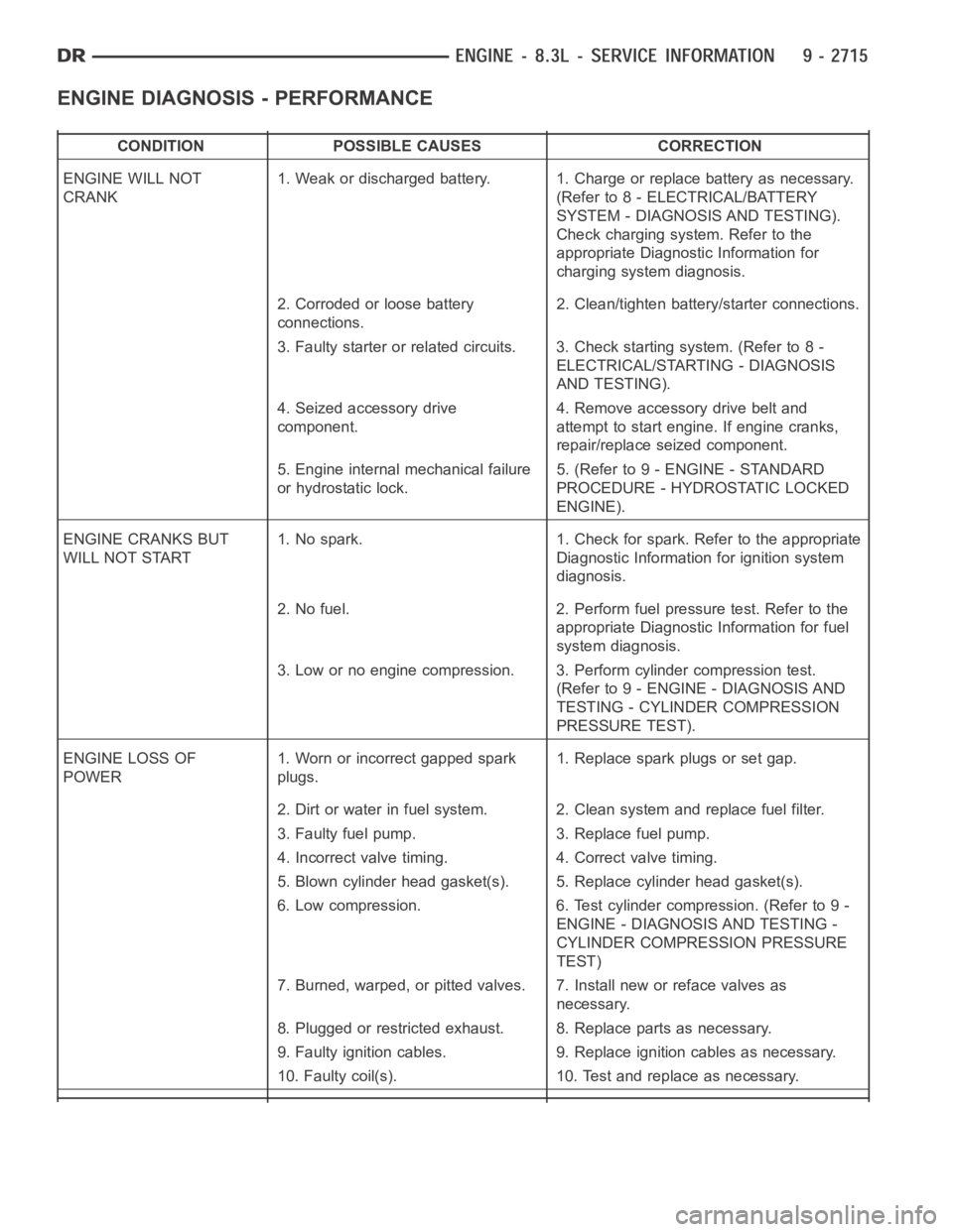
ENGINE DIAGNOSIS - PERFORMANCE
CONDITION POSSIBLE CAUSES CORRECTION
ENGINE WILL NOT
CRANK1. Weak or discharged battery. 1. Charge or replace battery as necessary.
(Refer to 8 - ELECTRICAL/BATTERY
SYSTEM - DIAGNOSIS AND TESTING).
Check charging system. Refer to the
appropriate Diagnostic Information for
charging system diagnosis.
2. Corroded or loose battery
connections.2. Clean/tighten battery/starter connections.
3. Faulty starter or related circuits. 3. Check starting system. (Refer to8-
ELECTRICAL/STARTING - DIAGNOSIS
AND TESTING).
4. Seized accessory drive
component.4. Remove accessory drive belt and
attempt to start engine. If engine cranks,
repair/replace seized component.
5. Engine internal mechanical failure
or hydrostatic lock.5. (Refer to 9 - ENGINE - STANDARD
PROCEDURE - HYDROSTATIC LOCKED
ENGINE).
ENGINE CRANKS BUT
WILL NOT START1. No spark. 1. Check for spark. Refer to the appropriate
Diagnostic Information for ignition system
diagnosis.
2. No fuel. 2. Perform fuel pressure test. Refer to the
appropriate Diagnostic Information for fuel
system diagnosis.
3. Low or no engine compression. 3. Perform cylinder compression test.
(Refer to 9 - ENGINE - DIAGNOSIS AND
TESTING - CYLINDER COMPRESSION
PRESSURE TEST).
ENGINE LOSS OF
POWER1. Worn or incorrect gapped spark
plugs.1. Replace spark plugs or set gap.
2. Dirt or water in fuel system. 2. Clean system and replace fuel filter.
3. Faulty fuel pump. 3. Replace fuel pump.
4. Incorrect valve timing. 4. Correct valve timing.
5. Blown cylinder head gasket(s). 5. Replace cylinder head gasket(s).
6. Low compression. 6. Test cylinder compression. (Refer to 9 -
ENGINE - DIAGNOSIS AND TESTING -
CYLINDER COMPRESSION PRESSURE
TEST)
7. Burned, warped, or pitted valves. 7. Install new or reface valves as
necessary.
8. Plugged or restricted exhaust. 8. Replace parts as necessary.
9. Faulty ignition cables. 9. Replace ignition cables as necessary.
10. Faulty coil(s). 10. Test and replace as necessary.
Page 2025 of 5267
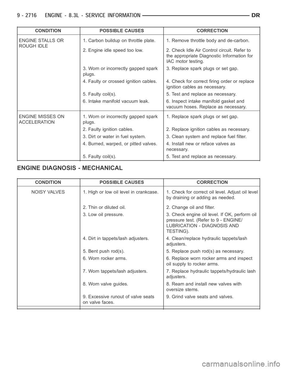
CONDITION POSSIBLE CAUSES CORRECTION
ENGINE STALLS OR
ROUGH IDLE1. Carbon buildup on throttle plate. 1. Remove throttle body and de-carbon.
2. Engine idle speed too low. 2. Check Idle Air Control circuit. Refer to
the appropriate Diagnostic Information for
IAC motor testing.
3. Worn or incorrectly gapped spark
plugs.3. Replace spark plugs or set gap.
4. Faulty or crossed ignition cables. 4. Check for correct firing order or replace
ignition cables as necessary.
5. Faulty coil(s). 5. Test and replace as necessary.
6. Intake manifold vacuum leak. 6. Inspect intake manifold gasket and
vacuum hoses. Replace as necessary.
ENGINE MISSES ON
ACCELERATION1. Worn or incorrectly gapped spark
plugs.1. Replace spark plugs or set gap.
2. Faulty ignition cables. 2. Replace ignition cables as necessary.
3. Dirt or water in fuel system. 3. Clean system and replace fuel filter.
4. Burned, warped, or pitted valves. 4. Install new or reface valves as
necessary.
5. Faulty coil(s). 5. Test and replace as necessary.
ENGINE DIAGNOSIS - MECHANICAL
CONDITION POSSIBLE CAUSES CORRECTION
NOISY VALVES 1. High or low oil level incrankcase. 1. Check for correct oil level. Adjust oil level
by draining or adding as needed.
2. Thin or diluted oil. 2. Change oil and filter.
3. Low oil pressure. 3. Check engine oil level. If OK, perform oil
pressure test. (Refer to 9 - ENGINE/
LUBRICATION - DIAGNOSIS AND
TESTING).
4. Dirt in tappets/lash adjusters. 4. Clean/replace hydraulic tappets/lash
adjusters.
5. Bent push rod(s). 5. Replace push rod(s) as necessary.
6. Worn rocker arms. 6. Replace worn rocker arms and inspect
oil supply to rocker arms.
7. Worn tappets/lash adjusters. 7. Replace hydraulic tappets/hydrauliclash
adjusters.
8. Worn valve guides. 8. Ream and install new valves with
oversize stems.
9. Excessive runout of valve seats
on valve faces.9. Grind valve seats and valves.
Page 2027 of 5267
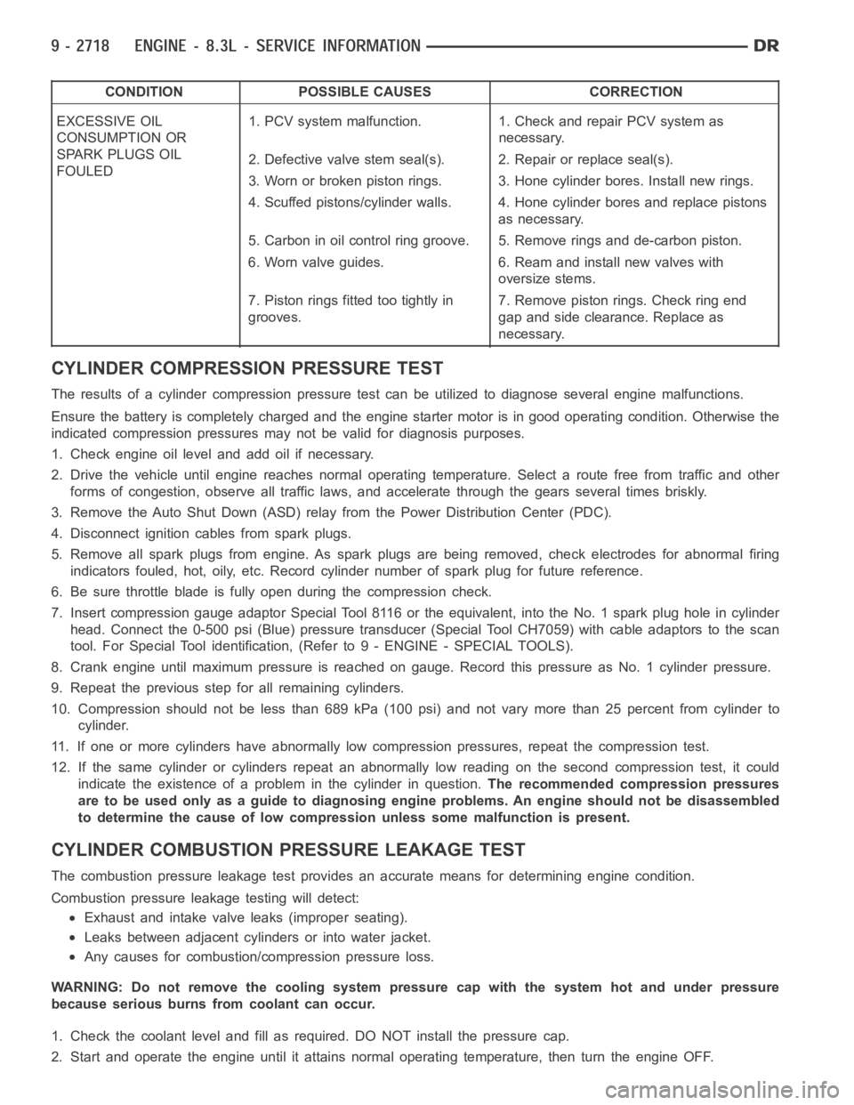
CONDITION POSSIBLE CAUSES CORRECTION
EXCESSIVE OIL
CONSUMPTION OR
SPARK PLUGS OIL
FOULED1. PCV system malfunction. 1. Check and repair PCV system as
necessary.
2. Defective valve stem seal(s). 2. Repair or replace seal(s).
3. Worn or broken piston rings. 3. Hone cylinder bores. Install new rings.
4. Scuffed pistons/cylinder walls. 4. Hone cylinder bores and replace pistons
as necessary.
5. Carbon in oil control ring groove. 5. Remove rings and de-carbon piston.
6. Worn valve guides. 6. Ream and install new valves with
oversize stems.
7. Piston rings fitted too tightly in
grooves.7. Remove piston rings. Check ring end
gap and side clearance. Replace as
necessary.
CYLINDER COMPRESSION PRESSURE TEST
The results of a cylinder compressionpressure test can be utilized to diagnose several engine malfunctions.
Ensurethebatteryiscompletelychargedandtheenginestartermotorisingood operating condition. Otherwise the
indicated compression pressures may not be valid for diagnosis purposes.
1. Check engine oil level and add oil if necessary.
2. Drive the vehicle until engine reaches normal operating temperature. Select a route free from traffic and other
forms of congestion, observe all traffic laws, and accelerate through thegears several times briskly.
3. Remove the Auto Shut Down (ASD) relay from the Power Distribution Center(PDC).
4. Disconnect ignition cables from spark plugs.
5. Remove all spark plugs from engine. As spark plugs are being removed, check electrodes for abnormal firing
indicators fouled, hot, oily, etc. Record cylinder number of spark plug for future reference.
6. Be sure throttle blade is fully open during the compression check.
7. Insert compression gauge adaptor Special Tool 8116 or the equivalent, into the No. 1 spark plug hole in cylinder
head. Connect the 0-500 psi (Blue) pressure transducer (Special Tool CH7059) with cable adaptors to the scan
tool. For Special Tool identification, (Refer to 9 - ENGINE - SPECIAL TOOLS).
8. Crank engine until maximum pressure is reached on gauge. Record this pressure as No. 1 cylinder pressure.
9. Repeat the previous step for all remaining cylinders.
10. Compression should not be less than 689 kPa (100 psi) and not vary more than 25 percent from cylinder to
cylinder.
11. If one or more cylinders have abnormally low compression pressures, repeat the compression test.
12. If the same cylinder or cylinders repeat an abnormally low reading on the second compression test, it could
indicate the existence of a problem in the cylinder in question.The recommended compression pressures
are to be used only as a guide to diagnosing engine problems. An engine should not be disassembled
to determine the cause of low compression unless some malfunction is present.
CYLINDER COMBUSTIONPRESSURE LEAKAGE TEST
The combustion pressure leakage test provides an accurate means for determining engine condition.
Combustion pressure leakage testing will detect:
Exhaust and intake valve leaks (improper seating).
Leaks between adjacent cylinders or into water jacket.
Any causes for combustion/compression pressure loss.
WARNING: Do not remove the cooling system pressure cap with the system hot and under pressure
because serious burns from coolant can occur.
1. Check the coolant level and fill as required. DO NOT install the pressurecap.
2. Start and operate the engine until it attains normal operating temperature, then turn the engine OFF.
Page 2072 of 5267
SPRINGS/SEALS-VALVE
DIAGNOSIS AND TESTING
VA LV E S P R I N G T E S T I N G
The valve springs should be tested whenever
removed for inspection, reconditioning, or replace-
ment.
1. Obtain specifications for spring tension at specified
spring length (Refer to 9 - ENGINE - SPECIFICA-
TIONS).
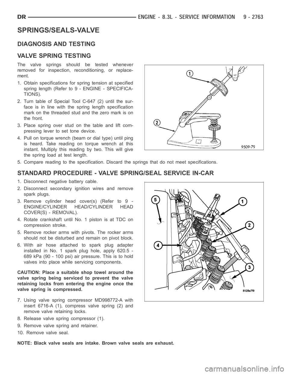
2. Turn table of Special Tool C-647 (2) until the sur-
face is in line with the spring length specification
mark on the threaded stud and the zero mark is on
the front.
3.Placespringoverstudonthetableandliftcom-
pressing lever to set tone device.
4. Pull on torque wrench (beam or dial type) until ping
is heard. Take reading on torque wrench at this
instant. Multiply this reading by two. This will give
the spring load at test length.
5. Compare reading to the specification. Discard the springs that do not meet specifications.
STANDARD PROCEDURE - VALVE SPRING/SEAL SERVICE IN-CAR
1. Disconnect negative battery cable.
2. Disconnect secondary ignition wires and remove
spark plugs.
3. Remove cylinder head cover(s) (Refer to 9 -
ENGINE/CYLINDER HEAD/CYLINDER HEAD
COVER(S) - REMOVAL).
4. Rotate crankshaft until No. 1 piston is at TDC on
compression stroke.
5. Remove rocker arms with pivots. The rocker arms
should not be disturbed and remain on pivot block.
6. With air hose attached to spark plug adapter
installed in No. 1 spark plug hole, apply 620.5 -
689 kPa (90 - 100 psi) air pressure. This is to hold
valves into place while servicing components.
CAUTION: Place a suitable shop towel around the
valve spring being serviced to prevent the valve
retaining locks from entering the engine once the
valve spring is compressed.
7. Using valve spring compressor MD998772-A with
insert 6716-A (1), compress valve spring (2) and
remove valve retaining locks.
8. Release valve spring compressor (1).
9. Remove valve spring and retainer.
10. Remove valve seal.
NOTE: Black valve seals are intake. Brown valve seals are exhaust.
Page 2143 of 5267
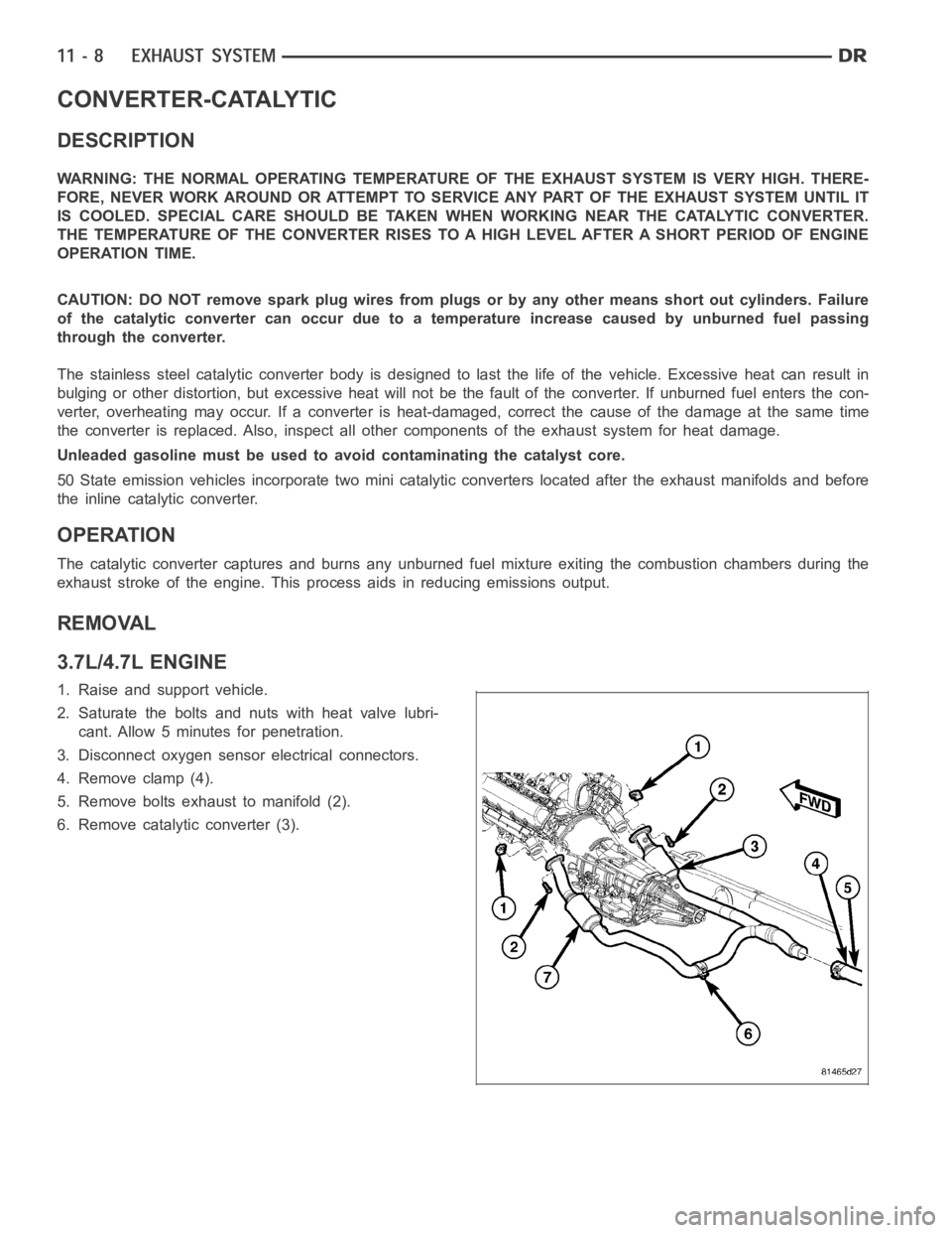
CONVERTER-CATALYTIC
DESCRIPTION
WARNING: THE NORMAL OPERATING TEMPERATURE OF THE EXHAUST SYSTEM IS VERY HIGH. THERE-
FORE, NEVER WORK AROUND OR ATTEMPT TO SERVICE ANY PART OF THE EXHAUST SYSTEMUNTIL IT
IS COOLED. SPECIAL CARE SHOULD BE TAKEN WHEN WORKING NEAR THE CATALYTIC CONVERTER.
THE TEMPERATURE OF THE CONVERTER RISES TO A HIGH LEVEL AFTER A SHORT PERIOD OFENGINE
OPERATION TIME.
CAUTION: DO NOT remove spark plug wires from plugs or by any other means short out cylinders. Failure
of the catalytic converter can occur due to a temperature increase caused by unburned fuel passing
through the converter.
The stainless steel catalytic converter body is designed to last the life of the vehicle. Excessive heat can result in
bulging or other distortion, but excessive heat will not be the fault of theconverter. If unburned fuel enters the con-
verter, overheating may occur. If a converter is heat-damaged, correct the cause of the damage at the same time
the converter is replaced. Also, inspect all other components of the exhaust system for heat damage.
Unleaded gasoline must be used to avoid contaminating the catalyst core.
50 State emission vehicles incorporate two mini catalytic converters located after the exhaust manifolds and before
the inline catalytic converter.
OPERATION
The catalytic converter captures and burns any unburned fuel mixture exiting the combustion chambers during the
exhaust stroke of the engine. This process aids in reducing emissions output.
REMOVAL
3.7L/4.7L ENGINE
1. Raise and support vehicle.
2. Saturate the bolts and nuts with heat valve lubri-
cant. Allow 5 minutes for penetration.
3. Disconnect oxygen sensor electrical connectors.
4. Remove clamp (4).
5. Remove bolts exhaust to manifold (2).
6. Remove catalytic converter (3).