2006 DODGE RAM SRT-10 height
[x] Cancel search: heightPage 2006 of 5267
VALVE - OIL PRESSURE RELIEF
REMOVAL
1. Disconnect the battery negative cables.
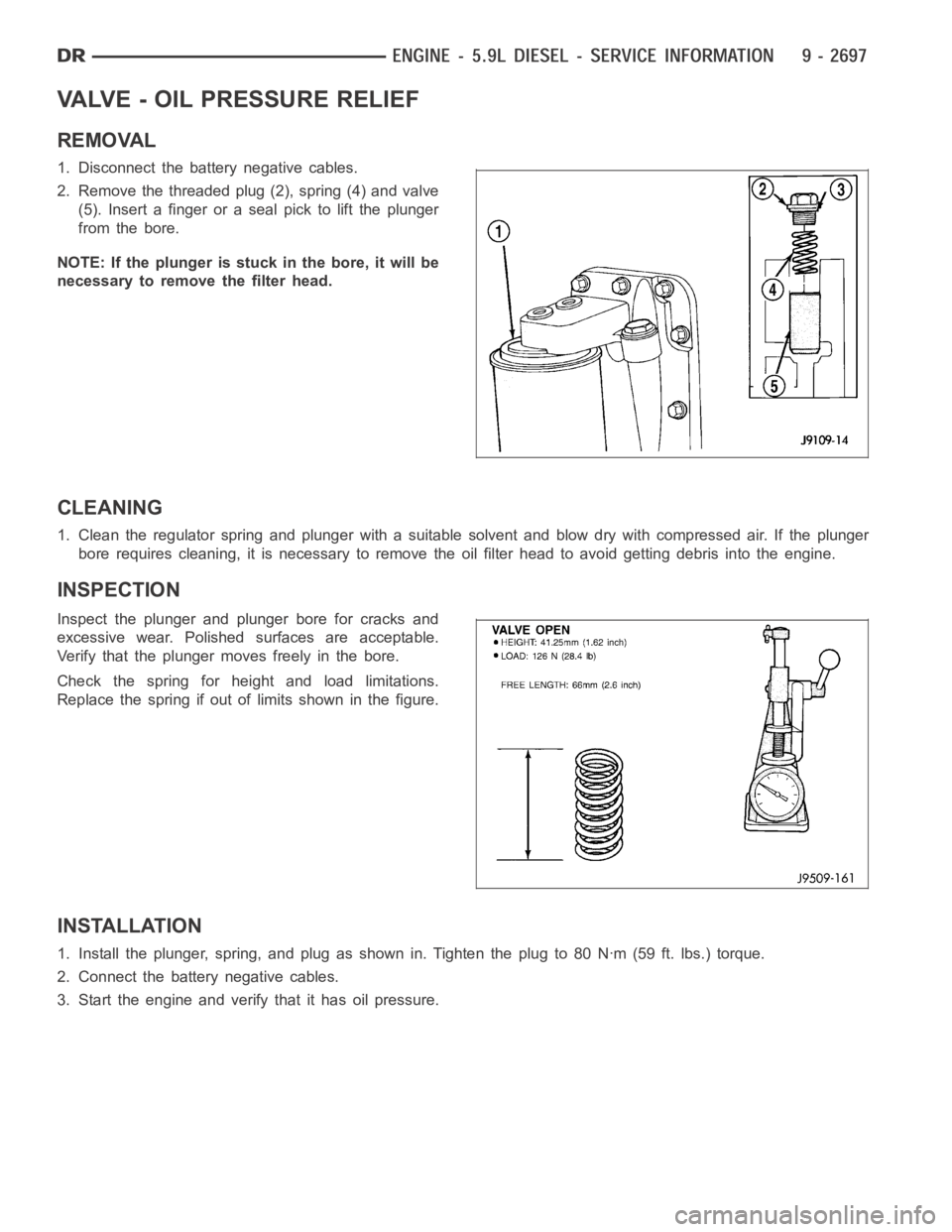
2. Remove the threaded plug (2), spring (4) and valve
(5). Insert a finger or a seal pick to lift the plunger
from the bore.
NOTE: If the plunger is stuck in the bore, it will be
necessary to remove the filter head.
CLEANING
1. Clean the regulator spring and plunger with a suitable solvent and blow dry with compressed air. If the plunger
bore requires cleaning, it is necessaryto remove the oil filter head to avoid getting debris into the engine.
INSPECTION
Inspect the plunger and plunger bore for cracks and
excessive wear. Polished surfaces are acceptable.
Verify that the plunger moves freely in the bore.
Check the spring for height and load limitations.
Replace the spring if out of limits shown in the figure.
INSTALLATION
1. Install the plunger, spring, and plug as shown in. Tighten the plug to 80 Nꞏm (59 ft. lbs.) torque.
2. Connect the battery negative cables.
3. Start the engine and verify that it has oil pressure.
Page 2041 of 5267
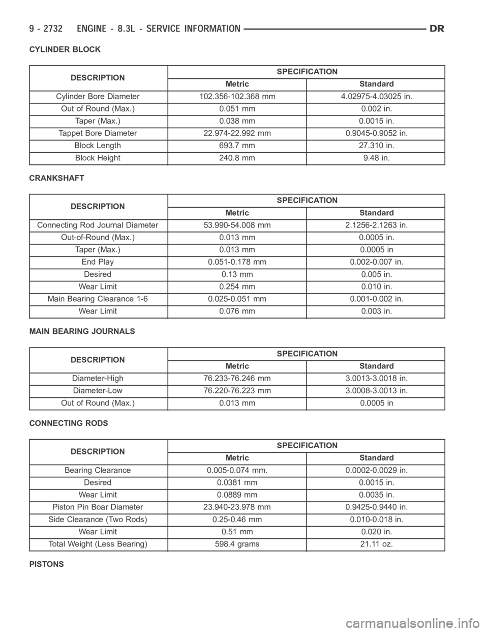
CYLINDER BLOCK
DESCRIPTIONSPECIFICATION
Metric Standard
Cylinder Bore Diameter 102.356-102.368 mm 4.02975-4.03025 in.
Out of Round (Max.) 0.051 mm 0.002 in.
Taper (Max.) 0.038 mm 0.0015 in.
Tappet Bore Diameter 22.974-22.992 mm 0.9045-0.9052 in.
Block Length 693.7 mm 27.310 in.
Block Height 240.8 mm 9.48 in.
CRANKSHAFT
DESCRIPTIONSPECIFICATION
Metric Standard
Connecting Rod Journal Diameter 53.990-54.008 mm 2.1256-2.1263 in.
Out-of-Round (Max.) 0.013 mm 0.0005 in.
Taper (Max.) 0.013 mm 0.0005 in
End Play 0.051-0.178 mm 0.002-0.007 in.
Desired 0.13 mm 0.005 in.
Wear Limit 0.254 mm 0.010 in.
Main Bearing Clearance 1-6 0.025-0.051 mm 0.001-0.002 in.
Wear Limit 0.076 mm 0.003 in.
MAIN BEARING JOURNALS
DESCRIPTIONSPECIFICATION
Metric Standard
Diameter-High 76.233-76.246 mm 3.0013-3.0018 in.
Diameter-Low 76.220-76.223 mm 3.0008-3.0013 in.
Out of Round (Max.) 0.013 mm 0.0005 in
CONNECTING RODS
DESCRIPTIONSPECIFICATION
Metric Standard
Bearing Clearance 0.005-0.074 mm. 0.0002-0.0029 in.
Desired 0.0381mm 0.0015in.
Wear Limit 0.0889 mm 0.0035 in.
Piston Pin Boar Diameter 23.940-23.978 mm 0.9425-0.9440 in.
Side Clearance (Two Rods) 0.25-0.46 mm 0.010-0.018 in.
Wear Limit 0.51 mm 0.020 in.
Total Weight (Less Bearing) 598.4 grams 21.11 oz.
PISTONS
Page 2044 of 5267
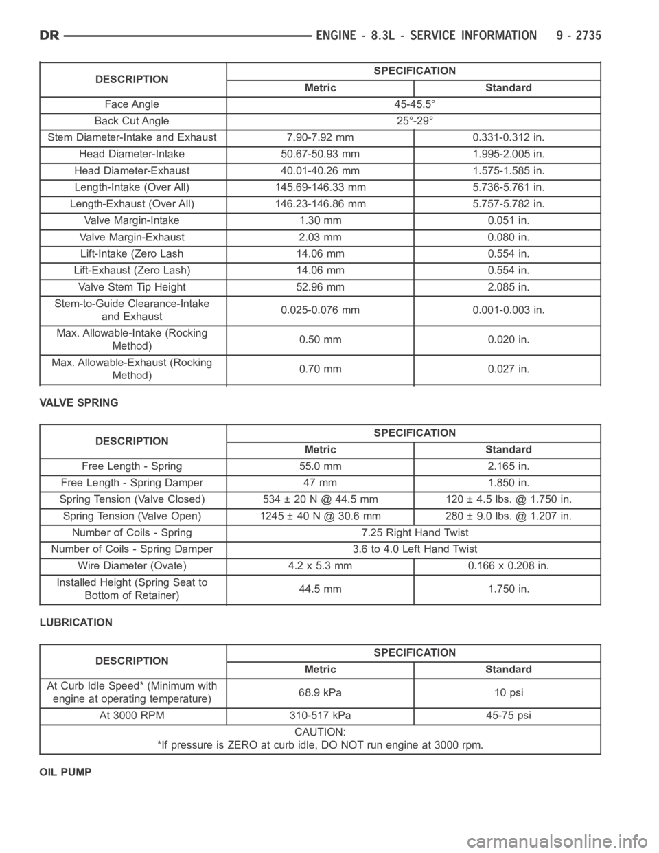
DESCRIPTIONSPECIFICATION
Metric Standard
Face Angle 45-45.5°
Back Cut Angle 25°-29°
Stem Diameter-Intake and Exhaust 7.90-7.92 mm 0.331-0.312 in.
Head Diameter-Intake 50.67-50.93 mm 1.995-2.005 in.
Head Diameter-Exhaust 40.01-40.26 mm 1.575-1.585 in.
Length-Intake (Over All) 145.69-146.33 mm 5.736-5.761 in.
Length-Exhaust (Over All) 146.23-146.86 mm 5.757-5.782 in.
Valve Margin-Intake 1.30 mm 0.051 in.
Valve Margin-Exhaust 2.03 mm 0.080 in.
Lift-Intake (Zero Lash 14.06 mm 0.554 in.
Lift-Exhaust (Zero Lash) 14.06 mm 0.554 in.
Valve Stem Tip Height 52.96 mm 2.085 in.
Stem-to-Guide Clearance-Intake
and Exhaust0.025-0.076 mm 0.001-0.003 in.
Max. Allowable-Intake (Rocking
Method)0.50 mm 0.020 in.
Max. Allowable-Exhaust (Rocking
Method)0.70 mm 0.027 in.
VALVE SPRING
DESCRIPTIONSPECIFICATION
Metric Standard
Free Length - Spring 55.0 mm 2.165 in.
Free Length - Spring Damper 47 mm 1.850 in.
Spring Tension (Valve Closed) 534 ± 20 N @ 44.5 mm 120 ± 4.5 lbs. @ 1.750 in.
Spring Tension (Valve Open) 1245 ± 40 N @ 30.6 mm 280 ± 9.0 lbs. @ 1.207 in.
Number of Coils - Spring 7.25 Right Hand Twist
Number of Coils - Spring Damper 3.6 to 4.0 Left Hand Twist
Wire Diameter (Ovate) 4.2 x 5.3 mm 0.166 x 0.208 in.
Installed Height (Spring Seat to
Bottom of Retainer)44.5 mm 1.750 in.
LUBRICATION
DESCRIPTIONSPECIFICATION
Metric Standard
At Curb Idle Speed* (Minimum with
engine at operating temperature)68.9 kPa 10 psi
At 3000 RPM 310-517 kPa 45-75 psi
CAUTION:
*If pressure is ZERO at curb idle, DO NOT run engine at 3000 rpm.
OIL PUMP
Page 2074 of 5267
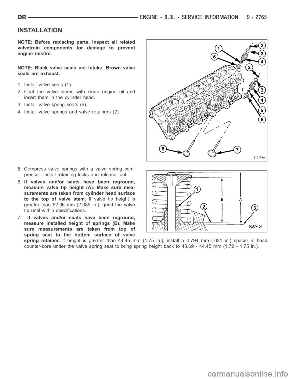
INSTALLATION
NOTE: Before replacing parts, inspect all related
valvetrain components for damage to prevent
engine misfire.
NOTE: Black valve seals are intake. Brown valve
seals are exhaust.
1. Install valve seals (1).
2. Coat the valve stems with clean engine oil and
insert them in the cylinder head.
3. Install valve spring seats (6).
4. Install valve springs and valve retainers (2).
5. Compress valve springs with a valve spring com-
pressor. Install retaining locks and release tool.
6.If valves and/or seats have been reground,
measure valve tip height (A). Make sure mea-
surements are taken from cylinder head surface
to the top of valve stem.If valve tip height is
greater than 52.96 mm (2.085 in.), grind the valve
tip until within specifications.
7.If valves and/or seats have been reground,
measure installed height of springs (B). Make
sure measurements are taken from top of
spring seat to the bottom surface of valve
spring retainer.If height is greater than 44.45 mm (1.75 in.), install a 0.794 mm (.031 in.) spacer in head
counter-bore under the valve spring seat to bring spring height back to 43.69 - 44.45 mm (1.72 - 1.75 in.).
Page 2207 of 5267
*First choice - Gas Metal Arc Welding Process:Butt joints - apply two layers (passes) of weld metal. First pass
should only fill approximately1⁄2the thickness. Vertical position welds - maintain electrode wire at leading edge of
weld puddle while traveling down hill to produce maximum penetration intothe sleeve. These techniques work for
FCAW as well.
**E7018new electrodes may be exposed to the atmosphere for up to ten hours with no harmful effect.
Reconditioning schedules should come from the manufacturer.
FRAME DIMENSIONS
NOTE: Frame dimensions are listed in metric scale. All dimensions are fromcenter to center of Principal
Locating Point (PLP), or from center to center of PLP and fastener location.
VEHICLE PREPARATION
Position the vehicle on a level work surface. Using screw or bottle jacks, adjust the vehicle PLP heights to the
specified dimension above a level work surface. Vertical dimensions can be taken from the work surface to the
locations indicated were applicable.
INDEX
DESCRIPTION FIGURE
1500 STANDARD CAB - 2 WHEEL DRIVE 1
1500 STANDARD CAB - 4 WHEEL DRIVE 2
1500 QUAD CAB - 2 WHEEL DRIVE 3
1500 QUAD CAB - 4 WHEEL DRIVE 4
140.5 IN WHEELBASE - HEAVY DUTY - 2 WHEEL DRIVE 5
140.5 IN WHEELBASE - HEAVY DUTY - 4 WHEEL DRIVE 6
160.5 IN WHEELBASE - 2500 - 2 WHEEL DRIVE 7
160.5 IN WHEELBASE - 2500 - 4 WHEEL DRIVE 8
160.5 IN WHEELBASE - 3500 - 2 WHEEL DRIVE 9
160.5 IN WHEELBASE - 3500 - 2 WHEEL DRIVE 10
Page 2298 of 5267
RELAY - FUEL PUMP
DESCRIPTION
The 5–pin, 12–volt, fuel pump relay is located in the Power Distribution Center (PDC). Refer to the label on the PDC
cover for relay location.
OPERATION
The Powertrain Control Module (PCM) energizes the electric fuel pump through the fuel pump relay. The fuel pump
relay is energized by first applying battery voltage to it when the ignition key is turned ON, and then applying a
ground signal to the relay from the PCM.
Whenever the ignition key is turned ON, the electric fuel pump will operate. But, the PCM will shut-down the ground
circuit to the fuel pump relay in approximately 1–3 seconds unless the engine is operating or the starter motor is
engaged.
REMOVAL
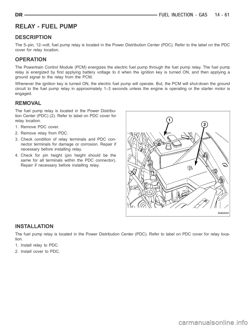
The fuel pump relay is located in the Power Distribu-
tion Center (PDC) (2). Refer to label on PDC cover for
relay location.
1. Remove PDC cover.
2. Remove relay from PDC.
3. Check condition of relay terminals and PDC con-
nector terminals for damage or corrosion. Repair if
necessary before installing relay.
4. Check for pin height (pin height should be the
same for all terminals within the PDC connector).
Repair if necessary before installing relay.
INSTALLATION
The fuel pump relay is located in the Power Distribution Center (PDC). Refer to label on PDC cover for relay loca-
tion.
1. Install relay to PDC.
2. Install cover to PDC.
Page 4601 of 5267
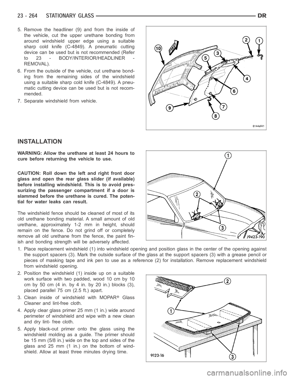
5. Remove the headliner (9) and from the inside of
the vehicle, cut the upper urethane bonding from
around windshield upper edge using a suitable
sharp cold knife (C-4849). A pneumatic cutting
device can be used but is not recommended (Refer
to 23 - BODY/INTERIOR/HEADLINER -
REMOVAL).
6. From the outside of the vehicle, cut urethane bond-
ing from the remaining sides of the windshield
using a suitable sharp cold knife (C-4849). A pneu-
matic cutting device can be used but is not recom-
mended.
7. Separate windshield from vehicle.
INSTALLATION
WARNING: Allow the urethane at least 24 hours to
cure before returning the vehicle to use.
CAUTION: Roll down the left and right front door
glass and open the rear glass slider (if available)
before installing windshield. This is to avoid pres-
surizing the passenger compartment if a door is
slammed before the urethane is cured. The poten-
tial for water leaks can result.
The windshield fence should be cleaned of most of its
old urethane bonding material. A small amount of old
urethane, approximately 1-2 mm in height, should
remain on the fence. Do not grind off or completely
remove all old urethane from the fence, the paint fin-
ish and bonding strength will be adversely affected.
1. Place replacement windshield (1) into windshield opening and positionglass in the center of the opening against
the support spacers (3). Mark the outside surface of the glass at the support spacers (3) with a grease pencil or
pieces of masking tape and ink pen to use as a reference (2) for installation. Remove replacement windshield
from windshield opening.
2. Position the windshield (1) inside up on a suitable
work surface with two padded, wood 10 cm by 10
cm by 50 cm (4 in. by 4 in. by 20 in.) blocks (3),
placed parallel 75 cm (2.5 ft.) apart.
3. Clean inside of windshield with MOPAR
Glass
Cleaner and lint-free cloth.
4. Apply clear glass primer 25 mm (1 in.) wide around
perimeter of windshield and wipe with a new clean
and dry lint- free cloth.
5. Apply black-out primer onto the glass using the
windshield molding as a guide. The primer should
be 15 mm (5/8 in.) wide on the top and sides of the
glass and 25 mm (1 in.) on the bottom of wind-
shield. Allow at least three minutes drying time.
Page 4602 of 5267
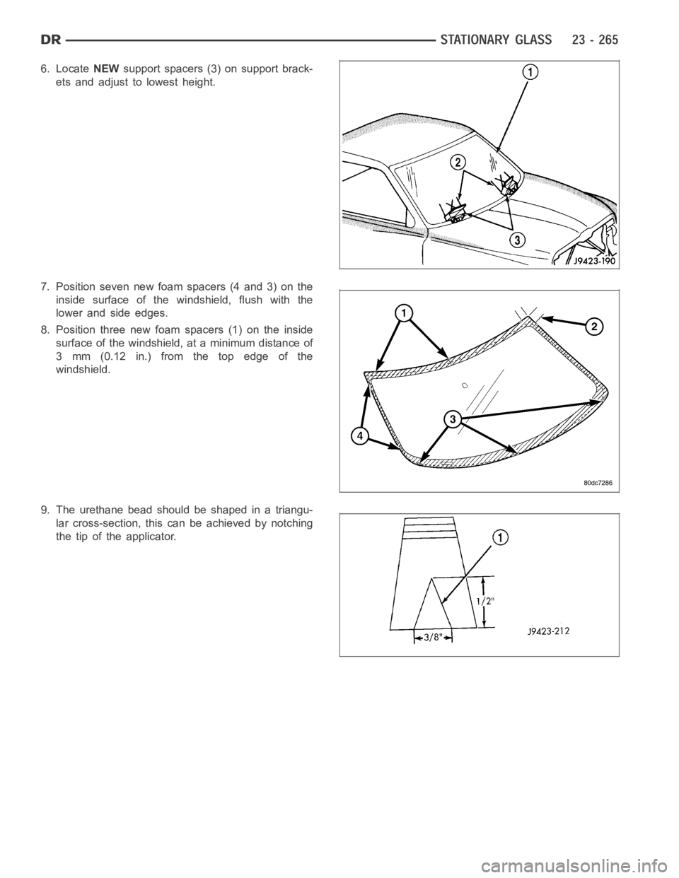
6. LocateNEWsupport spacers (3) on support brack-
ets and adjust to lowest height.
7. Position seven new foam spacers (4 and 3) on the
inside surface of the windshield, flush with the
lower and side edges.
8. Position three new foam spacers (1) on the inside
surface of the windshield, at a minimum distance of
3 mm (0.12 in.) from the top edge of the
windshield.
9. The urethane bead should be shaped in a triangu-
lar cross-section, this canbeachievedbynotching
the tip of the applicator.