Page 2103 of 2893
���
�(�#�'���������������
�
���������������������)����
22-155
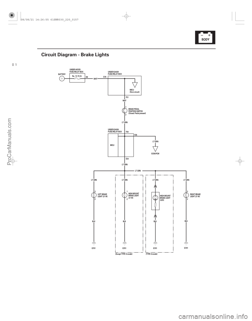
Circuit Diagram - Brake Lights
G16 F31
2 1
LT GRN
LT GRN
LT GRN E34 F30
MICU
2 3 2
1
G701 BLK
BLK
G701
ECM/PCM
LT GRN
LT GRN LT GRN WHT
G701 BLK
WHT
No. 12 (15 A)
BATTERY UNDER-HOOD
FUSE/RELAY BOX
MICU
(Horn circuit)
BRAKE PEDAL
POSITION SWITCH
(Closed: Pedal pressed)
LEFT BRAKE
LIGHT (21 W) HIGH MOUNT
BRAKE LIGHT
(21 W)
UNDER-DASH
FUSE/RELAY BOX
UNDER-DASH
FUSE/RELAY BOX
D8
F25
2 3
LT GRN
BLK
G701
LT GRN
HIGH MOUNT
BRAKE LIGHT
(LED)
(TYPE S model)
(Except TYPE S model) RIGHT BRAKE
LIGHT (21 W)
08/08/21 14:26:55 61SNR030_220_0157
ProCarManuals.com
DYNOMITE -2009-
Page 2105 of 2893
����
�µ
�µ
�µ
�µ �µ
�µ
DTC B1078:
YES
NO
YES
NO YES
NO
22-157
DTC Troubleshooting
UNDER-DASH FUSE/RELAY BOX CONNECTOR E (42P)
GND (BLK)
UNDER-D")
���
�(�#�'��������� �������������.�
�������������)����
�µ
�µ
�µ
�µ �µ
�µ
DTC B1078:
YES
NO
YES
NO YES
NO
22-157
DTC Troubleshooting
UNDER-DASH FUSE/RELAY BOX CONNECTOR E (42P)
GND (BLK)
UNDER-DASH FUSE/RELAY BOX CONNECTOR F (34P) GND (BLK)
GND (BLK)
Daytime Running Lights System
Error
NOTE: If you are troubleshooting multiple DTCs, be
sure to follow the instructions in B-CAN System
Diagnosis Test Mode A (see page 22-93).
1. Turn the ignition switch to ON (II).
2. Pull the parking brake lever.
3. Clear the DTCs with the HDS.
4. Release the parking brake lever.
5. Turn the ignition switch to LOCK (0), and then back to ON (II).
6. Check for DTCs with the HDS.
Go to step 7.
Intermittent failure. The daytime running
lights system is OK at this time. Check for loose or
poor connections.
7. Turn the headlight switch ON (high beam).
Go to step 8.
Go to step 10.
8. Turn the ignition switch to LOCK (0). 9. Measure the voltage between under-dash fuse/
relay box connector E (42P) terminals No. 6 and
No. 33 and body ground, and between under-dash
fuse/relay box connector F (34P) terminal No. 20
and body ground individually.
Faulty MICU; replace the under-dash fuse/
relay box (see page 22-66).
Repair an open in the BLK wire or poor
ground (G 401, G501, G601, G602).
10. Turn the ignition switch to LOCK (0) and turn the headlight switch OFF.
(cont’d)
Wire side of female terminalsWire side of female terminals
Is DTC B1078 indicated?
Do bot h head l i ght s ( hi gh beam) come on? I s t her e l ess t han 0.5 V ?
08/08/21 14:26:56 61SNR030_220_0159
ProCarManuals.com
DYNOMITE -2009-
Page 2111 of 2893
����
22-163
MICU Input Test
UNDER-DASH FUSE/RELAY BOX CONNECTOR E (42P)
BLK RED
GRN WHT
ORN
PNKPUR
WHT
GRY LT BLU UNDER-DASH FUSE/RELAY BOX CONNECT")
����
�(�#�'���������������
���������
�����
�������)����
22-163
MICU Input Test
UNDER-DASH FUSE/RELAY BOX CONNECTOR E (42P)
BLK RED
GRN WHT
ORN
PNKPUR
WHT
GRY LT BLU UNDER-DASH FUSE/RELAY BOX CONNECTOR F (34P)
UNDER-DASH FUSE/RELAY BOX CONNECTOR G (21P)
UNDER-DASH FUSE/RELAY BOX CONNECTOR S (20P) UNDER-DASH FUSE/RELAY BOX CONNECTOR T (34P) BLK
BLK BLK
RED
RED
RED ORN
PNK BLK
NOTE:
The MICU turns on the headlights (high beams) in a dimming mode for the Daytime Running Lights under the following conditions:
– With the ignition switch turned to ON (II)
– The headlight switch OFF
– The parking brake is released (parking brake switch OFF)
The DRL indicator will come on when one of the headlight (high beams) bulbs is blown, or if the high beam wiring has an open circuit with the daytime running lights ON.
If the vehicle is equipped with an optional remote control engine start system, the daytime running lights will not function when started with the remote start.
1. Before testing the lighting system, troubleshoot the system using B-CAN System Diagnosis Test Mode A (see page 22-93).
2. Check the No. 12 (10 A), No. 13 (10 A), No. 15 (7.5 A), No. 16 (15 A) , (10 A) , No. 17 (15 A) , (10 A) , No. 18 (20 A), No. 19 (15 A), No. 21 (30 A) , (20 A) , and No. 37 (7.5 A) fuses in the under-dash fuse/relay box. If any fuse
is blown, replace it and go to step 3.
1: With HID
2: Without HID
3. Disconnect under-dash fuse/relay box connectors E, F, G, S, and T. NOTE: All connector views are shown from wire side of female terminals.
(cont’d)
1212
12
08/08/21 14:26:58 61SNR030_220_0165
ProCarManuals.com
DYNOMITE -2009-
Page 2128 of 2893
���
�(�#�'���������������
�����
�����
���
� �����)���� ����
�(�#�'���������������
�����
�����
���
� �����)���
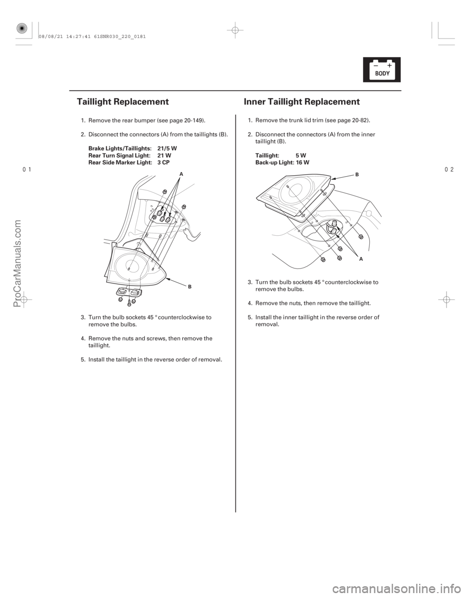
Brake Lights/Taillights: 21/5 W
Rear Turn Signal Light: 21 W
Rear Side Marker Light: 3 CP
Taillight: 5 W
Back-up Light: 16 W
22-17922-179
Taillight Replacement
Inner Taillight Replacement
A
B A
B
1. Remove the rear bumper (see page 20-149).
2. Disconnect the connectors (A) from the ta
illights (B).
3. Turn the bulb sockets 45 ° counterclockwise to remove the bulbs.
4. Remove the nuts and screws, then remove the taillight.
5. Install the taillight in the reverse order of removal. 1. Remove the trunk lid trim (see page 20-82).
2. Disconnect the connectors (A) from the inner
taillight (B).
3. Turn the bulb sockets 45 ° counterclockwise to remove the bulbs.
4. Remove the nuts, then remove the taillight.
5. Install the inner taillight in the reverse order of removal.
08/08/21 14:27:41 61SNR030_220_0181
ProCarManuals.com
DYNOMITE -2009-
Page 2129 of 2893
���� ���
����
�(�#����������������
�
�������
�����
� �����)���
License Plate Light: 5 W
High Mount Brake Light: 21 W
Except TYPE S model
22-18022-1")
���
�(�#�'���������������
���������������
� �����)���� ���
����
�(�#�'���������������
�
�������
�����
� �����)���
License Plate Light: 5 W
High Mount Brake Light: 21 W
Except TYPE S model
22-18022-180Exterior Lights
License Plate Light Replacement High Mount Brake Light
Replacement
A
B
C
A
B
C
A
1. Open the trunk lid, and remove the rear license trim (see page 20-168).
2. Disconnect the 2P connector (A) from the license plate light.
3. Release the bulb socket (B) from the lens (C) by pressing on the tabs.
4. Remove the lens from the trunk lid by pressing on the tabs.
5. Install the license plate light in the reverse order of removal. 1. Open the trunk lid.
2. Disconnect the 2P connector (A) from the high
mount brake light.
3. Turn the bulb socket (B) 45 ° counterclockwise to remove the bulb (C).
4. Remove the rear shelf (see page 20-78).
5. Remove the high mount brake light (A).
6. Install the high mount brake light in the reverse order of removal.
08/08/21 14:27:41 61SNR030_220_0182
ProCarManuals.com
DYNOMITE -2009-
Page 2130 of 2893
���
����
�(�#����������������
�
�����
���������������)����
TYPE S model
22-18122-181
Brake Pedal Position Switch Test
A B
A
B
1. Remove the two s")
���
�(�#�'���������������
�
�������
�����
� �����)���
����
�(�#�'���������������
�
�����
���������������)����
TYPE S model
22-18122-181
Brake Pedal Position Switch Test
A B
A
B
1. Remove the two screws from the high mount brakelight (A).
2. Disconnect the terminals (B) and remove the high mount brake light.
3. Install the high mount brake light in the r everse
order of removal. 1. Disconnect the 4P connector (A) from the brake
pedal position switch (B).
2. Check for continuity between terminals No. 1 and No. 2.
There should be continuity when the brake pedal is pressed.
There should be no continuity when the brake pedal is released.
3. Check for continuity between terminals No. 3 and No. 4 (with cruise control).
There should be no continuity when the brake pedal is pressed.
There should be continuity when the brake pedal is released.
4. If necessary, adjust or replace the switch, or adjust the pedal height (see page 19-6).
08/08/21 14:27:41 61SNR030_220_0183
ProCarManuals.com
DYNOMITE -2009-
Page 2131 of 2893
���
����
�(�#����������������
�
�����
���������������)����
TYPE S model
22-18122-181
Brake Pedal Position Switch Test
A B
A
B
1. Remove the two s")
���
�(�#�'���������������
�
�������
�����
� �����)���
����
�(�#�'���������������
�
�����
���������������)����
TYPE S model
22-18122-181
Brake Pedal Position Switch Test
A B
A
B
1. Remove the two screws from the high mount brakelight (A).
2. Disconnect the terminals (B) and remove the high mount brake light.
3. Install the high mount brake light in the r everse
order of removal. 1. Disconnect the 4P connector (A) from the brake
pedal position switch (B).
2. Check for continuity between terminals No. 1 and No. 2.
There should be continuity when the brake pedal is pressed.
There should be no continuity when the brake pedal is released.
3. Check for continuity between terminals No. 3 and No. 4 (with cruise control).
There should be no continuity when the brake pedal is pressed.
There should be continuity when the brake pedal is released.
4. If necessary, adjust or replace the switch, or adjust the pedal height (see page 19-6).
08/08/21 14:27:41 61SNR030_220_0183
ProCarManuals.com
DYNOMITE -2009-
Page 2188 of 2893
����
������(�#�'���������������
�����������������������)����
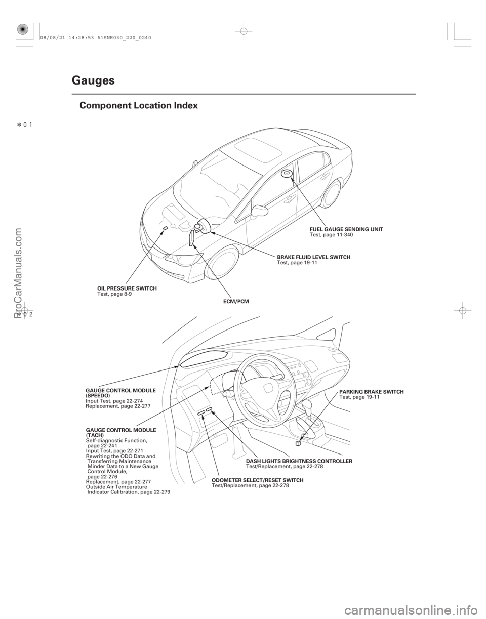
22-238Gauges
Component Location Index
OIL PRESSURE SWITCH
ECM/PCMBRAKE FLUID LEVEL SWITCH
FUEL GAUGE SENDING UNIT
GAUGE CONTROL MODULE
(TACH) ODOMETER SELECT/RESET SWITCHDASH LIGHTS BRIGHTNESS CONTROLLER
GAUGE CONTROL MODULE
(SPEEDO)
PARKING BRAKE SWITCH
Test, page 8-9
Test, page 19-11
Test, page 11-340
Self-diagnostic Function, page 22-241
Input Test, page 22-271
Rewriting the ODO Data and Transferring Maintenance
Minder Data to a New Gauge
Control Module,
page 22-276
Replacement, page 22-277
Outside Air Temperature Indicator Calibration, page 22-279 Test/Replacement, page 22-278Test/Replacement, page 22-278
Input Test, page 22-274
Replacement, page 22-277
Test, page 19-11
08/08/21 14:28:53 61SNR030_220_0240
ProCarManuals.com
DYNOMITE -2009-