Page 2040 of 2893
���
�µ
�µ
�µ
�µ
YES
NO
YES
NOUnit not communicating
22-9422-94Multiplex Integrated Control System
Troubleshooting - B-CAN System
Diagnosis Test Mode")
�(�#�'���������������������������������������)���
�µ
�µ
�µ
�µ
YES
NO
YES
NOUnit not communicating
22-9422-94Multiplex Integrated Control System
Troubleshooting - B-CAN System
Diagnosis Test Mode A (cont’d)
Troubleshooting - B-CAN System
Diagnosis Test Mode B
4. Select the system that has the problem from the
BODY ELECTRICAL menu, then select DTCs.
Go to step 5.
If the problem is related to one of the
following items, go to B-CAN System Diagnosis
Test Mode C (see page 22-95) if the system does
not stop or turn off. Go to Test Mode D (see page
22-96) if the system does not run or turn on.
Exterior lights
Turn signals
Entry light control
Interior lights
Horn (security and panic)
Wiper/washer
If the problem is related to one of the following
items, go to the troubleshooting for that individual
system. Gauge control module
Door-open and trunk-open indicators
Chimes (key-in, seat belt, lights-on, and parking brake)
Security
Keyless entry
Keyinterlock
Dash light brightness control
Audio system
Navigation (if equipped)
HandsFreeLink (if equipped)
5. Record all DTCs, and sort them by DTC type.
6. Troubleshoot the DTC(s) in this order: Battery voltage DTCs.
Internal error DTCs.
Loss of communication DTCs. Begintroubleshooting with the lowest number first
(Example: if DTC B1008 and B1011 are retrieved,
begin by troubleshooting B 1008).
Signal error DTCs. Do this diagnosis if any of the control units are not
communicating (Not Available is displayed in the HDS)
as found by the B-CAN System Diagnosis Test Mode A
(see page 22-93).
1. Using the HDS, select the system that has the symptom from the BODY ELECTRICAL menu.
2. Select DTCs, and then check for loss of communication DTCs.
Go to step 3.
Replace the MICU.
3. Do the input test for the unit not communicating with the HDS.
MICU (see page 22-109)
Gauge control module (see page 22- 271)
Immobilizer-keyless control unit (see page
22-330)
Climate control unit (see page 21-24)
HandsFreeLink control unit (see page 23-388)
Are any DTCs indicated?
Ar e any l oss of communi cat i on DT Cs i nd i cat ed ?
08/08/21 14:24:59 61SNR030_220_0096
ProCarManuals.com
DYNOMITE -2009-
Page 2041 of 2893
���
�µ
�µ
�µ
�µ
YES
NO
YES
NOUnit not communicating
22-9422-94Multiplex Integrated Control System
Troubleshooting - B-CAN System
Diagnosis Test Mode")
�(�#�'���������������������������������������)���
�µ
�µ
�µ
�µ
YES
NO
YES
NOUnit not communicating
22-9422-94Multiplex Integrated Control System
Troubleshooting - B-CAN System
Diagnosis Test Mode A (cont’d)
Troubleshooting - B-CAN System
Diagnosis Test Mode B
4. Select the system that has the problem from the
BODY ELECTRICAL menu, then select DTCs.
Go to step 5.
If the problem is related to one of the
following items, go to B-CAN System Diagnosis
Test Mode C (see page 22-95) if the system does
not stop or turn off. Go to Test Mode D (see page
22-96) if the system does not run or turn on.
Exterior lights
Turn signals
Entry light control
Interior lights
Horn (security and panic)
Wiper/washer
If the problem is related to one of the following
items, go to the troubleshooting for that individual
system. Gauge control module
Door-open and trunk-open indicators
Chimes (key-in, seat belt, lights-on, and parking brake)
Security
Keyless entry
Keyinterlock
Dash light brightness control
Audio system
Navigation (if equipped)
HandsFreeLink (if equipped)
5. Record all DTCs, and sort them by DTC type.
6. Troubleshoot the DTC(s) in this order: Battery voltage DTCs.
Internal error DTCs.
Loss of communication DTCs. Begintroubleshooting with the lowest number first
(Example: if DTC B1008 and B1011 are retrieved,
begin by troubleshooting B 1008).
Signal error DTCs. Do this diagnosis if any of the control units are not
communicating (Not Available is displayed in the HDS)
as found by the B-CAN System Diagnosis Test Mode A
(see page 22-93).
1. Using the HDS, select the system that has the symptom from the BODY ELECTRICAL menu.
2. Select DTCs, and then check for loss of communication DTCs.
Go to step 3.
Replace the MICU.
3. Do the input test for the unit not communicating with the HDS.
MICU (see page 22-109)
Gauge control module (see page 22- 271)
Immobilizer-keyless control unit (see page
22-330)
Climate control unit (see page 21-24)
HandsFreeLink control unit (see page 23-388)
Are any DTCs indicated?
Ar e any l oss of communi cat i on DT Cs i nd i cat ed ?
08/08/21 14:24:59 61SNR030_220_0096
ProCarManuals.com
DYNOMITE -2009-
Page 2045 of 2893
 (cont’d)
Driver’s door lock switch (UNLOCK)")
�µ
�µ
MICU
Item
YES
NO
22-98Multiplex Integrated Control System
Troubleshooting - B-CAN System Diagnosis Test Mode 1 and Test Mode 2
(without the HDS) (cont’d)
Driver’s door lock switch (UNLOCK)
Driver’s door lock switch (LOCK)
Driver’s door lock knob switch (UNLOCK)
Driver’s door lock knob switch (LOCK)
Driver’s door key cylinder switch (UNLOCK)
Driver’s door key cylinder switch (LOCK)
Front passenger’s door lock switch (UNLOCK)
Front passenger’s door lock switch (LOCK)
Front passenger’s door lock knob switch
(UNLOCK)
Left rear door lock knob switch (UNLOCK)
Right rear door lock knob switch (UNLOCK)
Driver’s door switch (OPEN)
Front passenger’s door switch (OPEN)
Left rear door switch (OPEN)
Right rear door switch (OPEN)
Trunk lid latch switch (OPEN)
Audio switch
Windshield wiper HI/LO switch
Windshield wiper INT/LO switch
Windshield wiper MIST switch
Windshield washer switch (ON)
Windshield wiper intermittent dwell time
controller
Windshield wiper motor park switch
Turn signal switch (LEFT)
Turn signal switch (RIGHT)
Hazard warning switch (ON)
Headlight switch (ON)
Headlight switch (OFF)
Lighting switch (ON)
Dimmer switch (ON)
Passing switch (ON)
Fog light switch (ON)
Hood switch (OPEN)
A/C pressure switch/thermal protector
Transmission range switch (P)
Ignition key cylinder switch
Brake switch (ON)
: A second key is necessary to check the key cylinder inputs.
Be sure to rotate the key cylinder switch two
times to each position (lock and lock, unlock
and unlock) to ensure the door lock knob
switch is in the appropriate position. Go to function and input test for the system
related to the failure.
Repair the open, short, or replace the faulty
switch.
Does the ceiling light work properly in all switch posi t i ons?
08/08/21 14:24:59 61SNR030_220_0100
ProCarManuals.com
DYNOMITE -2009-
Page 2094 of 2893
����
�(�#�'���������������������������������������)���
���
����
�(�#�'�������������������������������
�������)����
22-14622-146 Horns
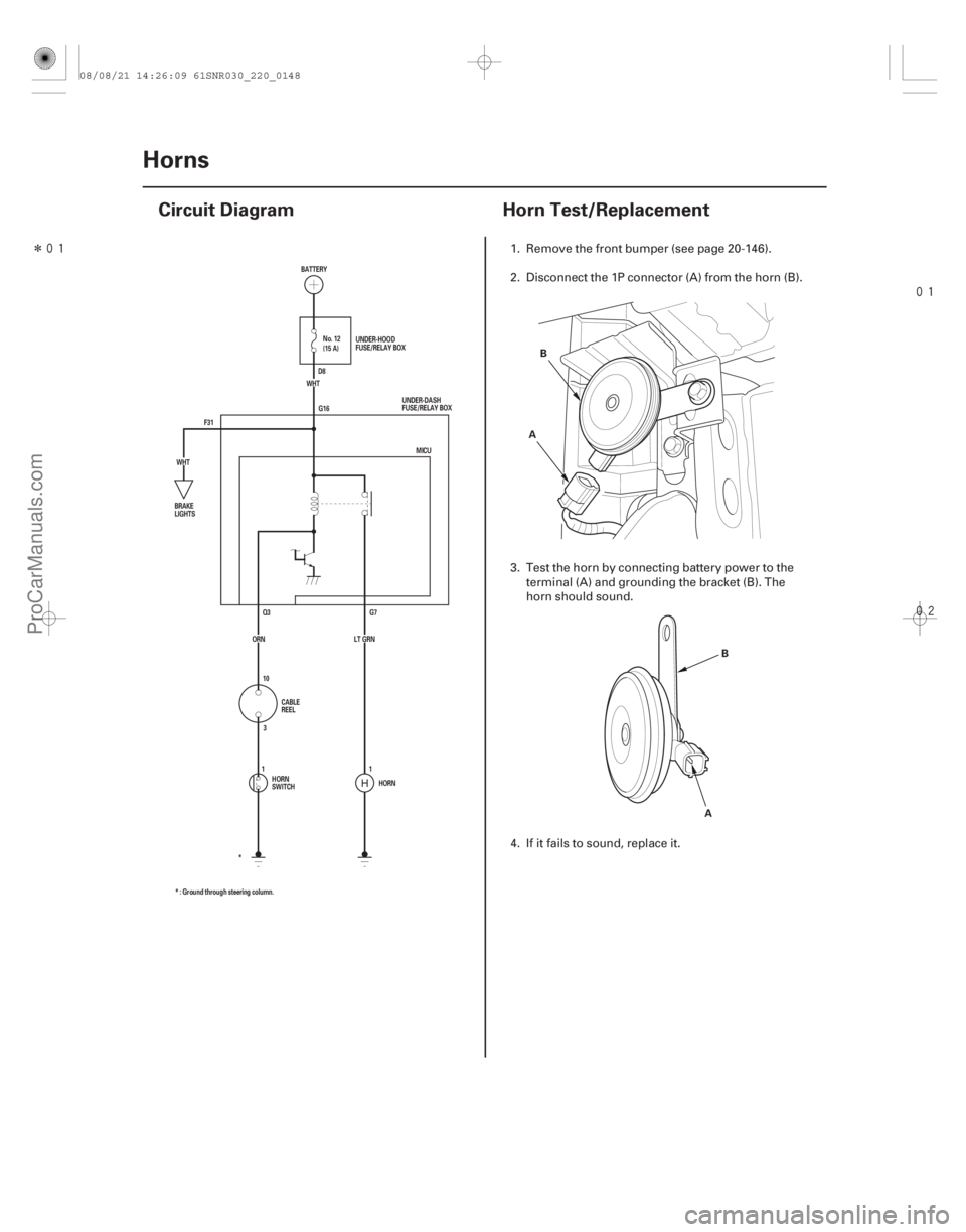
Circuit Diagram
Horn Test/Replacement
F31 G16
G7
Q3
HORN
* : Ground through steering column. * MICU
ORN LT GRN (15 A) No. 12
WHT
WHT BATTERY
UNDER-DASH
FUSE/RELAY BOX
BRAKE
LIGHTS
CABLE
REEL
HORN
SWITCH UNDER-HOOD
FUSE/RELAY BOX
D8
10 3
11A B
AB
1. Remove the front bumper (see page 20-146).
2. Disconnect the 1P connector (A) from the horn (B).
3. Test the horn by connecting battery power to the
terminal (A) and grounding the bracket (B). The
horn should sound.
4. If it fails to sound, replace it.
08/08/21 14:26:09 61SNR030_220_0148
ProCarManuals.com
DYNOMITE -2009-
Page 2096 of 2893
����
22-148Exterior Lights
Component Location Index
DAYTIME RUNNING LIGHTS CIRCUIT
(Built into the MICU)
HEADLIGHT
FRONTSIDEMARKERLIGHT
FRO")
����
������(�#�'���������������
�����������������������)����
22-148Exterior Lights
Component Location Index
DAYTIME RUNNING LIGHTS CIRCUIT
(Built into the MICU)
HEADLIGHT
FRONTSIDEMARKERLIGHT
FRONT PARKING LIGHT
FRONT TURN SIGNAL LIGHT FRONT SIDE TURN SIGNAL LIGHTS
HID UNIT
*1: With HID
*2: TYPE S and ’08 PREMIUM and ’09 models FOG LIGHT RELAY
FOG LIGHT TRANSMISSION RANGE SWITCH (A/T)
BACK-UP LIGHT SWITCH (M/T)
HIGH MOUNT BRAKE LIGHT
(Except TYPE S models) LICENSE PLATE LIGHTS
INNER TAILLIGHT
TAILLIGHT and BRAKE LIGHT
REAR TURN SIGNAL LIGHT BACK-UP LIGHT
REAR SIDE MARKER LIGHT
*1 *2
*2
Input Test, page 22-163
HID Bulb Replacement , page 22-168
Adjustment, page 22-173
Replacement, page 22-174
Bulb Replacement, page 22-177
Bulb Replacement, page 22-177
Bulb Replacement, page 22-178
Bulb Replacement, page 22-178 Replacement, page 22-192
HID Lamp System Troubleshooting, page 22-170
Replacement, page 22-169
Test, page 22-70
Replacement, page 22-175
Adjustment, page 22-176 Test, page 14-265
Test,
5-speed, page 13-5
6-speed, page 13-83
Replacement, page 22-180 Replacement, page 22-180
Replacement, page 22-179
Replacement, page 22-179
Replacement, page 22-179 Replacement, page 22-179
Replacement, page 22-179
*1
08/08/21 14:26:14 61SNR030_220_0150
ProCarManuals.com
DYNOMITE -2009-
Page 2097 of 2893
�����
�����
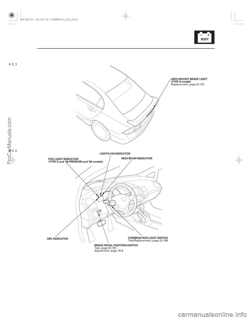
22-149
HIGH MOUNT BRAKE LIGHT
(TYPE S model)
HIGH BEAM INDICATOR
LIGHTS-ON INDICATOR
COMBINATION LIGHT SWITCH
BRAKE PEDAL POSITION SWITCH
FOG LIGHT INDICATOR
(TYPE S and ’08 PREMIUM and ’09 models)
DRL INDICATOR Replacement, page 22-181
Test/Replacement, page 22-166
Test, page 22-181
Adjustment, page 19-6
08/08/21 14:26:52 61SNR030_220_0151
ProCarManuals.com
DYNOMITE -2009-
Page 2098 of 2893
������(�#�'�����!���������
�����
�����������������)�
��
�´
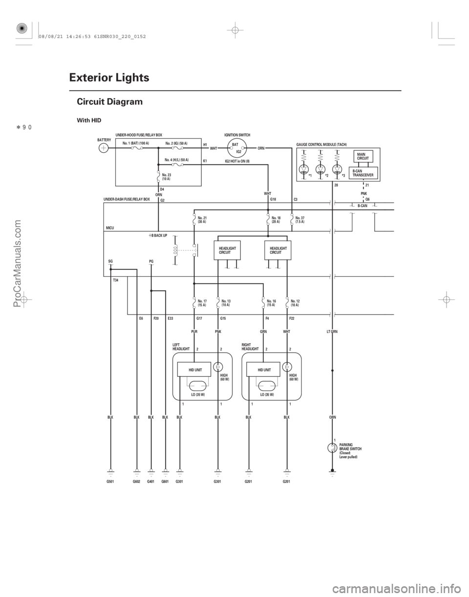
With HID
22-150Exterior Lights
Circuit Diagram
BATTERY
No. 1 (BAT) (100 A)
UNDER-HOOD FUSE/RELAY BOX
No. 4 (H/L) (50 A)
ORN No. 2 (IG) (50 A)
WHT
IGNITION SWITCH
BATIG2
WHT
ORN
IG2 HOT in ON (II)
G18 28 21
Q6
PNK
GAUGE CONTROL MODULE (TACH)
*1 *2 *3
LT GRNORN B-CAN
T34
G501 BLK
LO (35 W)
HID UNIT HID UNIT
LO (35 W)
G2
BLK
BLK
BLK
BLK
BLK BLK SG
E6
G602 G601 E33
F20
PG
BLK
G401 BBACKUP
MICU
G301 G201 F22
F4
G15
G17
2
2
11
1 2
1 2
G201
G301 GRN WHT
PUR
UNDER-DASH FUSE/RELAY BOX
PNK PARKING
BRAKE SWITCH
(Closed:
Lever pulled)B-CAN
TRANSCEIVER
MAIN
CIRCUIT
LEFT
HEADLIGHT RIGHT
HEADLIGHT
H1
K1
D4 C3
1
HEADLIGHT
CIRCUIT
HEADLIGHT
CIRCUIT
No. 37
(7.5 A)
No. 18
(20 A)
No. 21
(30 A)
No. 23
(10 A)
No. 17
(15 A)No. 13
(10 A) No. 16
(15 A)
No. 12
(10 A)
HIGH
(60 W) HIGH
(60 W)
08/08/21 14:26:53 61SNR030_220_0152
ProCarManuals.com
DYNOMITE -2009-
Page 2100 of 2893
������(�#�'�����!���������
�����
�����������������)�
��
�´
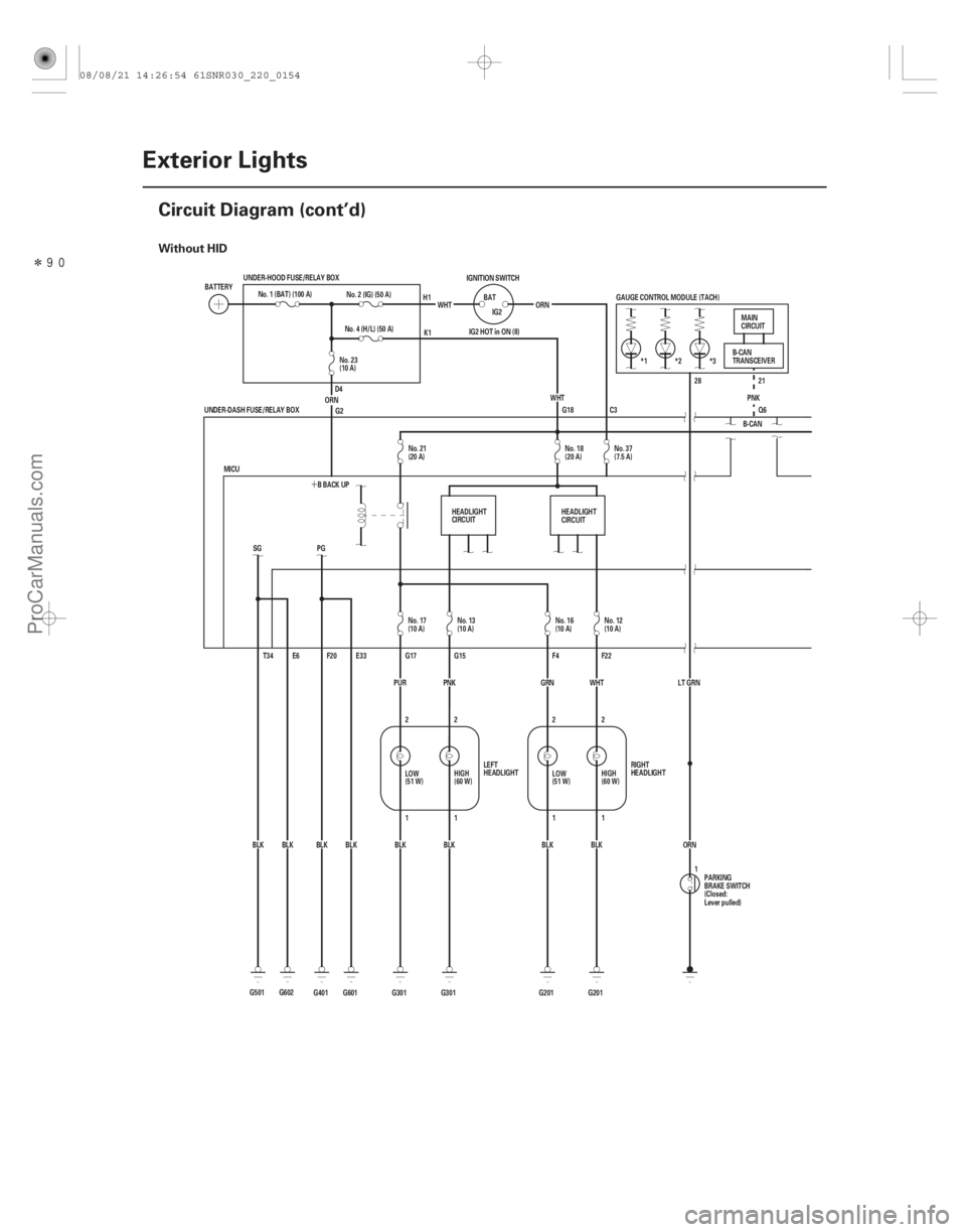
Without HID
22-152Exterior Lights
Circuit Diagram (cont’d)
G18
G501 BLKSG
T34 E6
G602BLK *3
*2
*1
IG2 HOT in ON (II) GAUGE CONTROL MODULE (TACH)
B-CANPNK
Q6 21
28
ORN
LT GRN
ORN
WHT
IG2
BAT
IGNITION SWITCH
No. 2 (IG) (50 A)
G2
BLK
BLK
BLK
BLK
BLK WHT
G601 E33
F20
PG
BLK
G401 BBACKUP
MICU ORNNo. 4 (H/L) (50 A)
G301 G201 F22
F4
G15
G17
2
2
11
1 2
1
2
G201
G301 GRN WHT
PUR
UNDER-DASH FUSE/RELAY BOX
UNDER-HOOD FUSE/RELAY BOX
PNK
No. 1 (BAT) (100 A)
BATTERY
RIGHT
HEADLIGHT
LEFT
HEADLIGHT MAIN
CIRCUIT
B-CAN
TRANSCEIVER
PARKING
BRAKE SWITCH
(Closed:
Lever pulled)
H1
K1
D4
1
C3
HEADLIGHT
CIRCUIT HEADLIGHT
CIRCUIT
No. 23
(10 A)
No. 21
(20 A) No. 18
(20 A)No. 37
(7.5 A)
No. 17
(10 A) No. 13
(10 A) No. 16
(10 A)No. 12
(10 A)
LOW
(51 W) HIGH
(60 W)
LOW
(51 W)HIGH
(60 W)
08/08/21 14:26:54 61SNR030_220_0154
ProCarManuals.com
DYNOMITE -2009-